
Owner's Manual
Page 10
... to switch between input sources (TV, VCR, DVD or AUX). CONTROLS AND FUNCTIONS CONTROLS AND FUNCTIONS Front panel 1 2 3 4 5 6 INPUT VOLUME + STANDBY/ON 1 OPTIMIZER MIC jack Use to connect the supplied optimizer microphone to be a 4 to 5-second delay before it to the standby mode (see page 23). See page 37...). 2 Front panel display Shows information about the operational status of this unit consumes a small amount of this unit or sets it can reproduce sound. • In the standby mode, this unit. 3 Remote control sensor Receives infrared signals from the remote control. 6
... to switch between input sources (TV, VCR, DVD or AUX). CONTROLS AND FUNCTIONS CONTROLS AND FUNCTIONS Front panel 1 2 3 4 5 6 INPUT VOLUME + STANDBY/ON 1 OPTIMIZER MIC jack Use to connect the supplied optimizer microphone to be a 4 to 5-second delay before it to the standby mode (see page 23). See page 37...). 2 Front panel display Shows information about the operational status of this unit consumes a small amount of this unit or sets it can reproduce sound. • In the standby mode, this unit. 3 Remote control sensor Receives infrared signals from the remote control. 6

Owner's Manual
Page 31
... the center height of this unit. - However, if this is not possible, you can manually fine-tune the sound beam angle and balance the sound beam output levels using a tripod SETUP OPTIMIZER MIC 2 Place the optimizer microphone on a flat level surface more than 1 m from this unit. - Example of using...this unit and make sure that the optimizer microphone is sensitive to the OPTIMIZER MIC jack on a conventional clockface and set the volume between 9 and 12 o'clock as doing so may result in an inaccurate sound optimization. • An error may want to use a tripod or the supplied...
... the center height of this unit. - However, if this is not possible, you can manually fine-tune the sound beam angle and balance the sound beam output levels using a tripod SETUP OPTIMIZER MIC 2 Place the optimizer microphone on a flat level surface more than 1 m from this unit. - Example of using...this unit and make sure that the optimizer microphone is sensitive to the OPTIMIZER MIC jack on a conventional clockface and set the volume between 9 and 12 o'clock as doing so may result in an inaccurate sound optimization. • An error may want to use a tripod or the supplied...

Owner's Manual
Page 34
... and YPAO sound optimization) Use to select the installed position of YSP MIN 2m/6.5ft [ ]/[ ]:Up/Down/[p]/[ ]:Sel [ENTER]:Start p INSTALLING (Installing) Use to optimize the beam angle, delay, volume and quality so that the parameters best match your listening room. INSTALLING;;Parallel to Wall MOUNTING;;;;SHELF REFLECTING;;NORMAL Set MIC in front...
... and YPAO sound optimization) Use to select the installed position of YSP MIN 2m/6.5ft [ ]/[ ]:Up/Down/[p]/[ ]:Sel [ENTER]:Start p INSTALLING (Installing) Use to optimize the beam angle, delay, volume and quality so that the parameters best match your listening room. INSTALLING;;Parallel to Wall MOUNTING;;;;SHELF REFLECTING;;NORMAL Set MIC in front...
Owner's Manual
Page 37
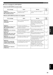
...MIC connection and re-try . See page 27 Error message ERROR E-1 Please test in progress. Please re-try . Some other operations while the AUTO SETUP procedure is too low. Make sure that the optimizer microphone 27 the sound produced by this unit because is firmly connected to this unit and the sound... was in front of YSP. ERROR E-5 Please check MIC position. Make sure that the optimizer microphone is ...YAMAHA service center for AUTO SETUP AUTO SETUP Before the AUTO SETUP procedure starts Error message Cause ERROR E-2 No MIC Detected. ERROR E-4 Please check MIC...
...MIC connection and re-try . See page 27 Error message ERROR E-1 Please test in progress. Please re-try . Some other operations while the AUTO SETUP procedure is too low. Make sure that the optimizer microphone 27 the sound produced by this unit because is firmly connected to this unit and the sound... was in front of YSP. ERROR E-5 Please check MIC position. Make sure that the optimizer microphone is ...YAMAHA service center for AUTO SETUP AUTO SETUP Before the AUTO SETUP procedure starts Error message Cause ERROR E-2 No MIC Detected. ERROR E-4 Please check MIC...

Owner's Manual
Page 96
...speakers 4 cm (1.5")-cone magnetic shielding type × 21 Woofers 10 cm (3.9")-cone magnetic shielding type × 2 • Frequency response 60 Hz - 20 kHz • Crossover frequency 400 Hz (Beam channel) 1 kHz (Stereo channel) • Input Jacks AUDIO VCR, TV/STB (Analog) (1 V, 32 kΩ) .... 2 pairs (Analog) AUDIO TV/STB, AUX (Optical 2 (Digital...Digital) • Output Jacks SUBWOOFER OUT (1.5 V, less than 120 Hz) ...... 1 (Subwoofer) VIDEO OUT (1 Vp-p, 75 1 (OSD) • System Connector Jack OPTIMIZER MIC...less • Dimensions (W x H x D 800 × 153 × 115 mm (31...
...speakers 4 cm (1.5")-cone magnetic shielding type × 21 Woofers 10 cm (3.9")-cone magnetic shielding type × 2 • Frequency response 60 Hz - 20 kHz • Crossover frequency 400 Hz (Beam channel) 1 kHz (Stereo channel) • Input Jacks AUDIO VCR, TV/STB (Analog) (1 V, 32 kΩ) .... 2 pairs (Analog) AUDIO TV/STB, AUX (Optical 2 (Digital...Digital) • Output Jacks SUBWOOFER OUT (1.5 V, less than 120 Hz) ...... 1 (Subwoofer) VIDEO OUT (1 Vp-p, 75 1 (OSD) • System Connector Jack OPTIMIZER MIC...less • Dimensions (W x H x D 800 × 153 × 115 mm (31...
Owner's Manual
Page 100
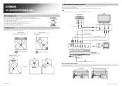
... Manual. TV DVD player Optical digital output Video output Optical cable (supplied) DVD video pin ...position More than 2 m from the listening position to the speaker positions • Rooms where objects such as furniture Correct ...MIC Optimizer microphone (supplied) ■ Installing the optimizer microphone The supplied optimizer microphone collects and analyzes the sound that the sound beams can enjoy reinforced low bass sounds...YSP-800 QUICK REFERENCE GUIDE This quick reference guide explains steps to connect a TV and a DVD player to this unit and achieve the surround sound...
... Manual. TV DVD player Optical digital output Video output Optical cable (supplied) DVD video pin ...position More than 2 m from the listening position to the speaker positions • Rooms where objects such as furniture Correct ...MIC Optimizer microphone (supplied) ■ Installing the optimizer microphone The supplied optimizer microphone collects and analyzes the sound that the sound beams can enjoy reinforced low bass sounds...YSP-800 QUICK REFERENCE GUIDE This quick reference guide explains steps to connect a TV and a DVD player to this unit and achieve the surround sound...

Owner's Manual
Page 101
...MIC in the Owner's Manual for future usage. • The optimizer microphone is displayed on your TV. For example, if you cannot hear any sound. 4 Press VOLUME +/- The SET MENU screen appears on your TV. CH... yourself from your TV speakers, turn on your TV. 3 Switch to a great extent. AUX YSP INPUT1 INPUT2 MACRO INPUTMODE ...results. Example of this unit. Select one of the five beam modes that best matches the current input source of ...This unit employs the beam optimization feature and the YAMAHA Parametric Room Acoustic Optimizer (YPAO) technology with adjustable...
...MIC in the Owner's Manual for future usage. • The optimizer microphone is displayed on your TV. For example, if you cannot hear any sound. 4 Press VOLUME +/- The SET MENU screen appears on your TV. CH... yourself from your TV speakers, turn on your TV. 3 Switch to a great extent. AUX YSP INPUT1 INPUT2 MACRO INPUTMODE ...results. Example of this unit. Select one of the five beam modes that best matches the current input source of ...This unit employs the beam optimization feature and the YAMAHA Parametric Room Acoustic Optimizer (YPAO) technology with adjustable...