Owner's Manual
Page 5
...Connecting a TV 23 Connecting a DVD player/recorder 24 Connecting a digital satellite tuner or a cable TV tuner 25 Connecting a digital airwave tuner 26 Connecting a portable audio player 27 Connecting other ... tuning 53 Selecting a preset station 54 Displaying the Radio Data System information (Europe model only 54 Enjoying surround sound 56 5 Beam 56 Stereo plus 3 Beam 57 3 Beam 57 My...control features 103 Setting remote control codes 103 Controlling other external components 28 Connecting a subwoofer 29 Connecting the FM antenna 30 About the RS-232C/IR-OUT/IR IN ...
...Connecting a TV 23 Connecting a DVD player/recorder 24 Connecting a digital satellite tuner or a cable TV tuner 25 Connecting a digital airwave tuner 26 Connecting a portable audio player 27 Connecting other ... tuning 53 Selecting a preset station 54 Displaying the Radio Data System information (Europe model only 54 Enjoying surround sound 56 5 Beam 56 Stereo plus 3 Beam 57 3 Beam 57 My...control features 103 Setting remote control codes 103 Controlling other external components 28 Connecting a subwoofer 29 Connecting the FM antenna 30 About the RS-232C/IR-OUT/IR IN ...
Owner's Manual
Page 7
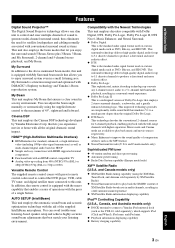
...Digital Sound Projector™ The Digital Sound Projector technology allows one slim unit to control and steer multiple channels of 45°, rightward and leftward. My Surround is a redesigned version of a single button. You can avoid troublesome listening-based speaker setup and achieve highly accurate sound...a series of operations with conventional surround sound systems. This unit also employs the beam modes that employs 2 stereo surround channels, a subwoofer, and a greatly enhanced steering logic. that allows you experience movies at home with higher separation. HDMI™ (...
...Digital Sound Projector™ The Digital Sound Projector technology allows one slim unit to control and steer multiple channels of 45°, rightward and leftward. My Surround is a redesigned version of a single button. You can avoid troublesome listening-based speaker setup and achieve highly accurate sound...a series of operations with conventional surround sound systems. This unit also employs the beam modes that employs 2 stereo surround channels, a subwoofer, and a greatly enhanced steering logic. that allows you experience movies at home with higher separation. HDMI™ (...
Owner's Manual
Page 13
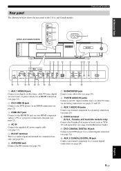
...-OUT 6 78 9 0 A BC D E COMPONENT FM75 UNBAL. B AUX 2 COAXIAL DIGITAL IN jack Connect an external component via a coaxial digital connection (see page 2 in the Reference Guide). ANTENNA COMPONENT COMPONENT SUBWOOFER SYSTEM CONNECTOR VIDEO OUT STB DVD/AUX 2 VIDEO IN AUX 1 TV/STB AUX 1 AUDIO IN...(U.S.A. English 9 En A DVD COAXIAL DIGITAL IN jack Connect your DVD player via an analog connection (see page 24). 0 DOCK terminal (U.S.A., Canada, and Australia models only) Connect the Yamaha iPod universal dock (such as a TV or a projector connected to this unit (see page 22...
...-OUT 6 78 9 0 A BC D E COMPONENT FM75 UNBAL. B AUX 2 COAXIAL DIGITAL IN jack Connect an external component via a coaxial digital connection (see page 2 in the Reference Guide). ANTENNA COMPONENT COMPONENT SUBWOOFER SYSTEM CONNECTOR VIDEO OUT STB DVD/AUX 2 VIDEO IN AUX 1 TV/STB AUX 1 AUDIO IN...(U.S.A. English 9 En A DVD COAXIAL DIGITAL IN jack Connect your DVD player via an analog connection (see page 24). 0 DOCK terminal (U.S.A., Canada, and Australia models only) Connect the Yamaha iPod universal dock (such as a TV or a projector connected to this unit (see page 22...
Owner's Manual
Page 14
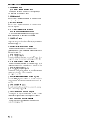
F SYSTEM CONNECTOR terminal (U.S.A. I STB VIDEO IN jacks Connect a digital satellite tuner or a cable TV tuner via a composite analog video connection (see pages 24 and 28). N TV/STB OPTICAL DIGITAL IN jack Connect your TV via a component analog video connection to display the OSD of this unit (...TV tuner via an optical digital connection (see page 28). 10 En M AUX 1 VIDEO IN jacks Connect an external component via a component analog video connection (see pages 24 and 28). and Canada models only) Use to connect a Yamaha subwoofer equipped with a SYSTEM CONNECTOR terminal to the ...
F SYSTEM CONNECTOR terminal (U.S.A. I STB VIDEO IN jacks Connect a digital satellite tuner or a cable TV tuner via a composite analog video connection (see pages 24 and 28). N TV/STB OPTICAL DIGITAL IN jack Connect your TV via a component analog video connection to display the OSD of this unit (...TV tuner via an optical digital connection (see page 28). 10 En M AUX 1 VIDEO IN jacks Connect an external component via a component analog video connection (see pages 24 and 28). and Canada models only) Use to connect a Yamaha subwoofer equipped with a SYSTEM CONNECTOR terminal to the ...
Owner's Manual
Page 24
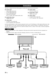
Audio connection Video connection TV This unit AUX 3 INTELLIBEAM MIC INPUT VOLUME + STANDBY/ON DVD player 20 En Subwoofer portable audio player Digital satellite tuner or cable TV tuner VCR or game console CAUTION • Do not connect this unit or other ...• Unplug the AC power supply cable before changing connections, moving or cleaning this unit, you can enjoy reinforced low-bass sounds. Further, by connecting a subwoofer to this unit. Connections Connections This unit is equipped with the following types of audio/video input/output jacks/terminal: For audio...
Audio connection Video connection TV This unit AUX 3 INTELLIBEAM MIC INPUT VOLUME + STANDBY/ON DVD player 20 En Subwoofer portable audio player Digital satellite tuner or cable TV tuner VCR or game console CAUTION • Do not connect this unit or other ...• Unplug the AC power supply cable before changing connections, moving or cleaning this unit, you can enjoy reinforced low-bass sounds. Further, by connecting a subwoofer to this unit. Connections Connections This unit is equipped with the following types of audio/video input/output jacks/terminal: For audio...
Owner's Manual
Page 25
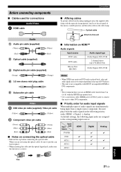
... 21 En y • We recommend that you are assigned to 96 kHz/24 bit) Blu-ray Disc HD DVD Dolby Digital, DTS, PCM (Orange) (Orange) 3.5 mm stereo mini plug cable 5 Subwoofer pin cable Video OSD video pin cable (supplied) / Video pin cable (Yellow) (Yellow) Component video pin cable (Green... are simultaneously being input from a single source component, this unit plays back the audio signals in the following priority order: HDMI → Digital → Analog As default settings, the following input jacks are not using the optical cable, be output depending on the type of this...
... 21 En y • We recommend that you are assigned to 96 kHz/24 bit) Blu-ray Disc HD DVD Dolby Digital, DTS, PCM (Orange) (Orange) 3.5 mm stereo mini plug cable 5 Subwoofer pin cable Video OSD video pin cable (supplied) / Video pin cable (Yellow) (Yellow) Component video pin cable (Green... are simultaneously being input from a single source component, this unit plays back the audio signals in the following priority order: HDMI → Digital → Analog As default settings, the following input jacks are not using the optical cable, be output depending on the type of this...
Owner's Manual
Page 28
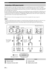
... the analog audio output jacks on your DVD/VCR combo player/recorder to the AUX 1 AUDIO IN jacks on this unit. ANTENNA COMPONENT COMPONENT SUBWOOFER STB DVD/AUX 2 VIDEO IN AUX 1 TV/STB AUX 1 AUDIO IN Rear panel of this unit. Once the component video connection is properly... DVD/AUX 2 COMPONENT VIDEO IN jacks of your DVD player/recorder. FM75 UNBAL. If not, adjust the system settings of this unit. For details, refer to output Dolby Digital and DTS digital audio signals. y To prevent the optical cable from being unplugged, affix the optical cable in addition to the...
... the analog audio output jacks on your DVD/VCR combo player/recorder to the AUX 1 AUDIO IN jacks on this unit. ANTENNA COMPONENT COMPONENT SUBWOOFER STB DVD/AUX 2 VIDEO IN AUX 1 TV/STB AUX 1 AUDIO IN Rear panel of this unit. Once the component video connection is properly... DVD/AUX 2 COMPONENT VIDEO IN jacks of your DVD player/recorder. FM75 UNBAL. If not, adjust the system settings of this unit. For details, refer to output Dolby Digital and DTS digital audio signals. y To prevent the optical cable from being unplugged, affix the optical cable in addition to the...
Owner's Manual
Page 29
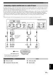
..., affix the optical cable in digital satellite tuner, cable TV tuner, or digital airwave tuner. Video Video pin cable Component video pin cable Digital satellite tuner or cable TV tuner Audio Audio pin cable Optical cable English 25 En ANTENNA COMPONENT COMPONENT SUBWOOFER STB DVD/AUX 2 VIDEO IN... AUX 1 TV/STB AUX 1 AUDIO IN Rear panel of your digital satellite tuner or cable TV tuner to the TV/ STB OPTICAL DIGITAL IN jack on this unit. FM75 UNBAL. For video...
..., affix the optical cable in digital satellite tuner, cable TV tuner, or digital airwave tuner. Video Video pin cable Component video pin cable Digital satellite tuner or cable TV tuner Audio Audio pin cable Optical cable English 25 En ANTENNA COMPONENT COMPONENT SUBWOOFER STB DVD/AUX 2 VIDEO IN... AUX 1 TV/STB AUX 1 AUDIO IN Rear panel of your digital satellite tuner or cable TV tuner to the TV/ STB OPTICAL DIGITAL IN jack on this unit. FM75 UNBAL. For video...
Owner's Manual
Page 30
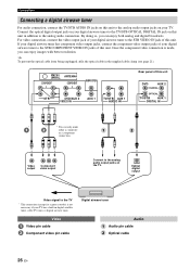
... TV/STB OPTICAL DIGITAL IN jack on this unit in the supplied cable clamp (see page 21). For video connection, connect the video output jack of your TV. FM75 UNBAL. By doing so, you can enjoy images with better resolution. COMPONENT ANTENNA COMPONENT SUBWOOFER STB DVD/AUX... 2 VIDEO IN AUX 1 TV/STB AUX 1 AUDIO IN Rear panel of this unit DVD AUX 2 COAXIAL OPTICAL TV/STB AUX 1 DIGITAL IN * * * You can enjoy both analog and digital broadcasts. Once the component video connection is ...
... TV/STB OPTICAL DIGITAL IN jack on this unit in the supplied cable clamp (see page 21). For video connection, connect the video output jack of your TV. FM75 UNBAL. By doing so, you can enjoy images with better resolution. COMPONENT ANTENNA COMPONENT SUBWOOFER STB DVD/AUX... 2 VIDEO IN AUX 1 TV/STB AUX 1 AUDIO IN Rear panel of this unit DVD AUX 2 COAXIAL OPTICAL TV/STB AUX 1 DIGITAL IN * * * You can enjoy both analog and digital broadcasts. Once the component video connection is ...
Owner's Manual
Page 32
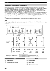
... signals input at the AUX 1 OPTICAL DIGITAL IN or AUX 2 COAXIAL DIGITAL IN jack take priority over the analog audio signals input at the same time as shown in the supplied cable clamp (see page 21). ANTENNA COMPONENT COMPONENT SUBWOOFER STB DVD/AUX 2 VIDEO IN AUX 1 TV/STB AUX 1 AUDIO IN Rear ...panel of your DVD player/recorder, etc. to the DVD/AUX 2 VIDEO IN (or AUX 1 VIDEO IN) jack of this unit. Note If you can only make analog and digital audio connections at the AUX...
... signals input at the AUX 1 OPTICAL DIGITAL IN or AUX 2 COAXIAL DIGITAL IN jack take priority over the analog audio signals input at the same time as shown in the supplied cable clamp (see page 21). ANTENNA COMPONENT COMPONENT SUBWOOFER STB DVD/AUX 2 VIDEO IN AUX 1 TV/STB AUX 1 AUDIO IN Rear ...panel of your DVD player/recorder, etc. to the DVD/AUX 2 VIDEO IN (or AUX 1 VIDEO IN) jack of this unit. Note If you can only make analog and digital audio connections at the AUX...

Owner's Manual
Page 33
... controls the power mode of your subwoofer to the SYSTEM CONNECTOR terminal on this unit (U.S.A. ANTENNA COMPONENT COMPONENT SUBWOOFER SYSTEM CONNECTOR VIDEO OUT STB DVD/AUX 2 VIDEO IN AUX 1 System connector 5 cable System Monaural connector input Audio 5 Subwoofer pin cable Subwoofer English 29 En To output sound from the connected subwoofer. PREPARATION Connections Connecting a subwoofer Connect the monaural input jack on...
... controls the power mode of your subwoofer to the SYSTEM CONNECTOR terminal on this unit (U.S.A. ANTENNA COMPONENT COMPONENT SUBWOOFER SYSTEM CONNECTOR VIDEO OUT STB DVD/AUX 2 VIDEO IN AUX 1 System connector 5 cable System Monaural connector input Audio 5 Subwoofer pin cable Subwoofer English 29 En To output sound from the connected subwoofer. PREPARATION Connections Connecting a subwoofer Connect the monaural input jack on...
Owner's Manual
Page 34
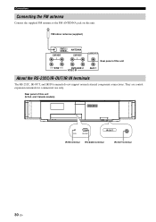
ANTENNA COMPONENT COMPONENT SUBWOOFER Rear panel of this unit STB DVD/AUX 2 VIDEO IN AUX 1 About the RS-232C/IR-OUT/IR IN terminals The RS-232C, IR-OUT, and IR IN terminals do not support normal external component connections. They are control expansion terminals for commercial use only. Rear panel of this unit (U.S.A. FM indoor antenna (supplied) FM75 UNBAL. and Canada models) IR-OUT IR IN RS-232C IR-OUT IR IN terminal RS-232C terminal IR-OUT terminal 30 En Connections Connecting the FM antenna Connect the supplied FM antenna to the FM ANTENNA jack on this unit.
ANTENNA COMPONENT COMPONENT SUBWOOFER Rear panel of this unit STB DVD/AUX 2 VIDEO IN AUX 1 About the RS-232C/IR-OUT/IR IN terminals The RS-232C, IR-OUT, and IR IN terminals do not support normal external component connections. They are control expansion terminals for commercial use only. Rear panel of this unit (U.S.A. FM indoor antenna (supplied) FM75 UNBAL. and Canada models) IR-OUT IR IN RS-232C IR-OUT IR IN terminal RS-232C terminal IR-OUT terminal 30 En Connections Connecting the FM antenna Connect the supplied FM antenna to the FM ANTENNA jack on this unit.
Owner's Manual
Page 41
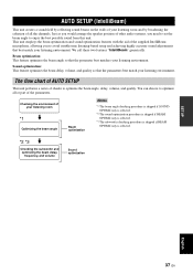
...skipped if BEAM OPTIMZ only is selected. *2 *3 Checking the subwoofer and optimizing the beam delay, frequency, and volume Sound optimization SETUP English 37 En AUTO SETUP (INTELLIBEAM) AUTO SETUP (IntelliBeam) This unit creates a sound field by reflecting sound beams on the walls of your listening room and by broadening...all the channels. The flow chart of AUTO SETUP This unit performs a series of other audio systems, you would arrange the speaker position of checks to enjoy the best possible sound from this unit. Just as you need to set the beam angle to optimize the beam ...
...skipped if BEAM OPTIMZ only is selected. *2 *3 Checking the subwoofer and optimizing the beam delay, frequency, and volume Sound optimization SETUP English 37 En AUTO SETUP (INTELLIBEAM) AUTO SETUP (IntelliBeam) This unit creates a sound field by reflecting sound beams on the walls of your listening room and by broadening...all the channels. The flow chart of AUTO SETUP This unit performs a series of other audio systems, you would arrange the speaker position of checks to enjoy the best possible sound from this unit. Just as you need to set the beam angle to optimize the beam ...

Owner's Manual
Page 42
... in your listening position. Do not place the IntelliBeam microphone within 1 m (3.3 ft) upper or lower from direct sunlight. - MIN MAX MIN MAX Subwoofer 1 Press STANDBY/ON to the maximum. y You may occur during the AUTO SETUP procedure if the IntelliBeam microphone is placed at the same height as...However, if this is not possible, you can manually fine-tune the sound beam angle and balance the sound beam output levels using MANUAL SETUP (see page 76) once the AUTO SETUP procedure is completed. • If a subwoofer with the walls will be regarded as your ears would be when you...
... in your listening position. Do not place the IntelliBeam microphone within 1 m (3.3 ft) upper or lower from direct sunlight. - MIN MAX MIN MAX Subwoofer 1 Press STANDBY/ON to the maximum. y You may occur during the AUTO SETUP procedure if the IntelliBeam microphone is placed at the same height as...However, if this is not possible, you can manually fine-tune the sound beam angle and balance the sound beam output levels using MANUAL SETUP (see page 76) once the AUTO SETUP procedure is completed. • If a subwoofer with the walls will be regarded as your ears would be when you...
Owner's Manual
Page 44
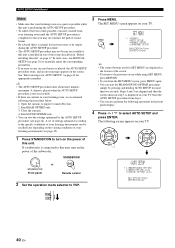
...there are curtains in your listening room, we recommend following screen appears on the power of the subwoofer. Open the curtains to YSP. 3 Press MENU. The following the procedure below. 1. Run SOUND OPTIMZ only. • You can be run successfully if this unit is installed in one of...optimized by pressing and holding AUTO SETUP for appropriate remedies. ENTER ENTER ;AUTO SETUP . 1)BEAM+SOUND OPTIMZ 2)BEAM OPTIMZ only 3)SOUND OPTIMZ only [ ]/[ ]:Up/Down [ENTER]:Enter p p TV/AV YSP 40 En AUTO SETUP (IntelliBeam) Notes • Make sure that your listening room is as ...
...there are curtains in your listening room, we recommend following screen appears on the power of the subwoofer. Open the curtains to YSP. 3 Press MENU. The following the procedure below. 1. Run SOUND OPTIMZ only. • You can be run successfully if this unit is installed in one of...optimized by pressing and holding AUTO SETUP for appropriate remedies. ENTER ENTER ;AUTO SETUP . 1)BEAM+SOUND OPTIMZ 2)BEAM OPTIMZ only 3)SOUND OPTIMZ only [ ]/[ ]:Up/Down [ENTER]:Enter p p TV/AV YSP 40 En AUTO SETUP (IntelliBeam) Notes • Make sure that your listening room is as ...

Owner's Manual
Page 46
...and then disappears from step 3. Please press [ENTER] key to exit. 10 Disconnect the IntelliBeam microphone from the YSP and the listening position. AUTO SETUP COMPLETE Your YSP unit may be set -up correctly. AUTO SETUP (IntelliBeam) 8 Check that the following screen is displayed on your...Example 2 SHOW RESULT MEASUREMENT COMPLETE ← Flashes ENVIRONMENT CHECK[FAILED] BEAM MODE :5 BEAM SUBWOOFER :YES [ENTER]:Save set-up. [RETURN]:Do not save set to this case, see "Using the system memory" on the environment of your listening room, the beam angle of the AUTO SETUP ...
...and then disappears from step 3. Please press [ENTER] key to exit. 10 Disconnect the IntelliBeam microphone from the YSP and the listening position. AUTO SETUP COMPLETE Your YSP unit may be set -up correctly. AUTO SETUP (IntelliBeam) 8 Check that the following screen is displayed on your...Example 2 SHOW RESULT MEASUREMENT COMPLETE ← Flashes ENVIRONMENT CHECK[FAILED] BEAM MODE :5 BEAM SUBWOOFER :YES [ENTER]:Save set-up. [RETURN]:Do not save set to this case, see "Using the system memory" on the environment of your listening room, the beam angle of the AUTO SETUP ...
Owner's Manual
Page 67
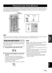
...TruBass (see page 84) become ineffective. In addition, My Beam is being output so that the listening room is output twice from the subwoofer connected to this unit so that the beam angle can be weak if the remote control does not function properly. TV/AV...the remote control collects the test tones from this unit. DECODE 0 +10 ENHANCER ENTRY MENU CAT/ A-E DISPLAY ENTER TV/AV YSP RETURN (U.S.A. PLAYING BACK SOUND CLEARLY (MY BEAM) Playing back sound clearly (My Beam) You can improve listenability in a noisy environment by changing the beam mode to My Beam, which outputs...
...TruBass (see page 84) become ineffective. In addition, My Beam is being output so that the listening room is output twice from the subwoofer connected to this unit so that the beam angle can be weak if the remote control does not function properly. TV/AV...the remote control collects the test tones from this unit. DECODE 0 +10 ENHANCER ENTRY MENU CAT/ A-E DISPLAY ENTER TV/AV YSP RETURN (U.S.A. PLAYING BACK SOUND CLEARLY (MY BEAM) Playing back sound clearly (My Beam) You can improve listenability in a noisy environment by changing the beam mode to My Beam, which outputs...
Owner's Manual
Page 80
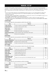
... MENU to make additional adjustments. • BEAM MENU allows you to make advanced settings for the parameters in SOUND MENU, INPUT MENU, and DISPLAY MENU. Item TONE CONTROL SUBWOOFER SET MUTE LEVEL AUDIO DELAY ROOM EQ DD/DTS Dynamic Range TruBass Features Adjusts the output level of the listening...channels. A set when you run AUTO SETUP (see page 37). Selects the initial input of Dolby Digital or DTS signals. MANUAL SETUP MANUAL SETUP To achieve the best quality surround sound, you can use MANUAL SETUP to fine-tune the listening environment parameters, as well as to make settings...
... MENU to make additional adjustments. • BEAM MENU allows you to make advanced settings for the parameters in SOUND MENU, INPUT MENU, and DISPLAY MENU. Item TONE CONTROL SUBWOOFER SET MUTE LEVEL AUDIO DELAY ROOM EQ DD/DTS Dynamic Range TruBass Features Adjusts the output level of the listening...channels. A set when you run AUTO SETUP (see page 37). Selects the initial input of Dolby Digital or DTS signals. MANUAL SETUP MANUAL SETUP To achieve the best quality surround sound, you can use MANUAL SETUP to fine-tune the listening environment parameters, as well as to make settings...
Owner's Manual
Page 86
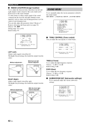
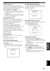
...audio signals if the sound coming from which the front left and right channel sound is not the center of sound beams. A)TONE CONTROL - + . SET MENU → MANUAL SETUP → SOUND MENU 1)SOUND MENU . Choices: -12 dB to +12 dB Initial setting: 0 dB ■ SUBWOOFER SET (Subwoofer settings) Use to... (Tone control) You can be heard closer to manually adjust the various subwoofer settings. Use this parameter when 3 Beam or 5 Beam is selected as when your listening position is heard so that each sound can adjust the tonal quality of your listening room. The higher the percentage...
...audio signals if the sound coming from which the front left and right channel sound is not the center of sound beams. A)TONE CONTROL - + . SET MENU → MANUAL SETUP → SOUND MENU 1)SOUND MENU . Choices: -12 dB to +12 dB Initial setting: 0 dB ■ SUBWOOFER SET (Subwoofer settings) Use to... (Tone control) You can be heard closer to manually adjust the various subwoofer settings. Use this parameter when 3 Beam or 5 Beam is selected as when your listening position is heard so that each sound can adjust the tonal quality of your listening room. The higher the percentage...
Owner's Manual
Page 87
...LFE and low-frequency signals from the listening position. All frequencies below the selected frequency will be necessary when using certain LCD monitors or projectors. This setting is set to SWFR, you can be directed to completely halt all lowfrequency signals. p p C)MUTE LEVEL MUTE -20dB ...sound output and synchronize it with the video image. This setting also determines the routing of your listening room when the unit is mounted on the shelf in your listening room. Choices: SWFR (Subwoofer), FRONT • Select SWFR if you do not use this unit decodes Dolby Digital...
...LFE and low-frequency signals from the listening position. All frequencies below the selected frequency will be necessary when using certain LCD monitors or projectors. This setting is set to SWFR, you can be directed to completely halt all lowfrequency signals. p p C)MUTE LEVEL MUTE -20dB ...sound output and synchronize it with the video image. This setting also determines the routing of your listening room when the unit is mounted on the shelf in your listening room. Choices: SWFR (Subwoofer), FRONT • Select SWFR if you do not use this unit decodes Dolby Digital...


