
Owner's Manual
Page 4
...to hot, and do not locate this unit in the home are complete. 8 Do not operate this unit. -... BEFORE OPERATING THIS UNIT. Burning objects (i.e. Contact qualified Yamaha service personnel when any damage resulting from the wall outlet...of plug to the instructions described below. This Class B digital apparatus complies with a humidifier) to prevent condensation inside this...moving this unit, press STANDBY/ON to modify or fix this sound system in the space below ) this unit, and/or personal ... a lightning storm. 14 Do not attempt to set this unit in standby mode, and disconnect the ...
...to hot, and do not locate this unit in the home are complete. 8 Do not operate this unit. -... BEFORE OPERATING THIS UNIT. Burning objects (i.e. Contact qualified Yamaha service personnel when any damage resulting from the wall outlet...of plug to the instructions described below. This Class B digital apparatus complies with a humidifier) to prevent condensation inside this...moving this unit, press STANDBY/ON to modify or fix this sound system in the space below ) this unit, and/or personal ... a lightning storm. 14 Do not attempt to set this unit in standby mode, and disconnect the ...
Owner's Manual
Page 5
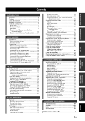
...digital airwave tuner 26 Connecting a portable audio player 27 Connecting other external components 28 Connecting a subwoofer 29 Connecting the FM antenna 30 About the RS-232C/IR-OUT/IR IN terminals ........ 30 Connecting the AC power supply cable 31 SETUP Getting started 32 Installing batteries in surround sound... 37 Installing the IntelliBeam microphone 38 Using AUTO SETUP (IntelliBeam 39 Using the system memory 44 Convenient usage of the system memory 44 Saving settings 44 Loading settings 45 BASIC OPERATION Playback 47 Selecting the input source 47 Playing back sources 48...
...digital airwave tuner 26 Connecting a portable audio player 27 Connecting other external components 28 Connecting a subwoofer 29 Connecting the FM antenna 30 About the RS-232C/IR-OUT/IR IN terminals ........ 30 Connecting the AC power supply cable 31 SETUP Getting started 32 Installing batteries in surround sound... 37 Installing the IntelliBeam microphone 38 Using AUTO SETUP (IntelliBeam 39 Using the system memory 44 Convenient usage of the system memory 44 Saving settings 44 Loading settings 45 BASIC OPERATION Playback 47 Selecting the input source 47 Playing back sources 48...
Owner's Manual
Page 6
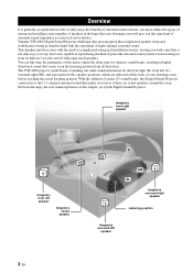
...sound experience of center (C) sound beams, this Digital Sound Projector creates true-to adjust the delay time for from all directions. Overview Overview It is generally accepted that in order to set up, but is not only easy to fully enjoy the benefits of surround sound at home... theater. You can fine-tune the parameters of powerful surround sound you have been waiting for separate sound beams, resulting in highly directional sound that complicated speaker setup and troublesome wiring go hand-in 2 woofers and 40 full-range small speakers. Yamaha YSP-4000 Digital Sound Projector ...
...sound experience of center (C) sound beams, this Digital Sound Projector creates true-to adjust the delay time for from all directions. Overview Overview It is generally accepted that in order to set up, but is not only easy to fully enjoy the benefits of surround sound at home... theater. You can fine-tune the parameters of powerful surround sound you have been waiting for separate sound beams, resulting in highly directional sound that complicated speaker setup and troublesome wiring go hand-in 2 woofers and 40 full-range small speakers. Yamaha YSP-4000 Digital Sound Projector ...

Owner's Manual
Page 9
...page 76 and "Remote control features" on page 56. Designs and specifications are subject to change in your listening room. See "Enjoying surround sound" on page 103. 5 En English In case of this unit to your operation. • This manual is printed prior to production. ...See "Installation" on page 47. 6 Change the beam modes and/or CINEMA DSP settings. See "Playback" on page 17. 2 Connect this unit unless otherwise specified. • y indicates a tip for your TV and other external components...
...page 76 and "Remote control features" on page 56. Designs and specifications are subject to change in your listening room. See "Enjoying surround sound" on page 103. 5 En English In case of this unit to your operation. • This manual is printed prior to production. ...See "Installation" on page 47. 6 Change the beam modes and/or CINEMA DSP settings. See "Playback" on page 17. 2 Connect this unit unless otherwise specified. • y indicates a tip for your TV and other external components...
Owner's Manual
Page 10
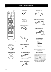
... 9 OFF SUR. DECODE 0 +10 ENHANCER ENTRY MENU CAT/ A-E DISPLAY ENTER TV/AV YSP RETURN VOLUME CH TV VOL Fasteners (×4) Cable clamp (×1) IntelliBeam microphone (×1) Optical cable (×1) Digital audio pin cable (×1) (Orange) Audio pin cable (×1) MUTE TV INPUT TV MUTE... CODE SET CH LEVEL TEST Cardboard microphone stand (×1) (White/Red) (U.S.A. Supplied accessories ...
... 9 OFF SUR. DECODE 0 +10 ENHANCER ENTRY MENU CAT/ A-E DISPLAY ENTER TV/AV YSP RETURN VOLUME CH TV VOL Fasteners (×4) Cable clamp (×1) IntelliBeam microphone (×1) Optical cable (×1) Digital audio pin cable (×1) (Orange) Audio pin cable (×1) MUTE TV INPUT TV MUTE... CODE SET CH LEVEL TEST Cardboard microphone stand (×1) (White/Red) (U.S.A. Supplied accessories ...
Owner's Manual
Page 11
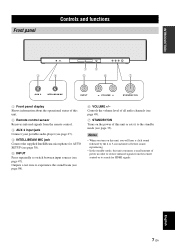
... the power of all audio channels (see page 49). 7 STANDBY/ON Turns on this unit, you will hear a click sound followed by the 4 to 5-second interval before sound reproducing. • In the standby mode, this unit. 2 Remote control sensor Receives infrared signals from the remote control or ...to search for AUTO SETUP (see page 38). 5 INPUT Press repeatedly to the standby mode (see page 98). 6 VOLUME +/- Controls the volume level of this unit or sets...
... the power of all audio channels (see page 49). 7 STANDBY/ON Turns on this unit, you will hear a click sound followed by the 4 to 5-second interval before sound reproducing. • In the standby mode, this unit. 2 Remote control sensor Receives infrared signals from the remote control or ...to search for AUTO SETUP (see page 38). 5 INPUT Press repeatedly to the standby mode (see page 98). 6 VOLUME +/- Controls the volume level of this unit or sets...
Owner's Manual
Page 12
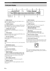
...SET parameter in MANUAL SETUP (see page 71). and Canada models only). 3 CINEMA DSP indicator Lights up when a sound field program is selected (see page 67). 4 PCM indicator Lights up when this unit. 9 SRS TruBass indicator Lights up when TruBass is turned on this unit is reproducing PCM (Pulse Code Modulation) digital... Input channel indicators Show information when you adjust the parameters of this unit is set (see page 71). C Radio Data System indicators (Europe model only) Show the current Radio Data System status. and Canada models only) Lights up when the sleep timer is receiving ...
...SET parameter in MANUAL SETUP (see page 71). and Canada models only). 3 CINEMA DSP indicator Lights up when a sound field program is selected (see page 67). 4 PCM indicator Lights up when this unit. 9 SRS TruBass indicator Lights up when TruBass is turned on this unit is reproducing PCM (Pulse Code Modulation) digital... Input channel indicators Show information when you adjust the parameters of this unit is set (see page 71). C Radio Data System indicators (Europe model only) Show the current Radio Data System status. and Canada models only) Lights up when the sleep timer is receiving ...
Owner's Manual
Page 15
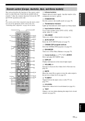
...once you want to operate. 2 STANDBY/ON Sets this unit. A VOLUME +/- Press again to restore the audio output to control this system to the standby mode (see page 33). ... of this window at the component you set the appropriate remote control codes. Aim this unit (see page 49). English 11 En B MUTE Mutes the sound. INTRODUCTION Controls and functions Remote control (...volume level (see page 49). DECODE 0 +10 ENHANCER ENTRY MENU A-E DISPLAY ENTER TV/AV YSP RETURN VOLUME CH TV VOL MUTE TV INPUT TV MUTE CH LEVEL TEST CODE SET H I ** J* K L M N O P Q R S t U* V* W*...
...once you want to operate. 2 STANDBY/ON Sets this unit. A VOLUME +/- Press again to restore the audio output to control this system to the standby mode (see page 33). ... of this window at the component you set the appropriate remote control codes. Aim this unit (see page 49). English 11 En B MUTE Mutes the sound. INTRODUCTION Controls and functions Remote control (...volume level (see page 49). DECODE 0 +10 ENHANCER ENTRY MENU A-E DISPLAY ENTER TV/AV YSP RETURN VOLUME CH TV VOL MUTE TV INPUT TV MUTE CH LEVEL TEST CODE SET H I ** J* K L M N O P Q R S t U* V* W*...
Owner's Manual
Page 16
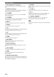
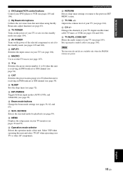
... POWER Turns on the power of your TV, digital satellite tuner, cable TV tuner, or VCR (see page 104). I AV POWER Turns on the power of your TV or sets it to the standby mode (see pages 105 ... of your TV (see pages 104 and 106). M A-E Switches the preset station group (A to the previous SET MENU screen. G My Beam microphone Collects the test tones from this unit is receiving an FM broadcast (see ...VCR control buttons Control your TV or other AV components. Q SUR. Select YSP when operating this unit. Note The functions L and M are available only when the FM stations are preset....
... POWER Turns on the power of your TV, digital satellite tuner, cable TV tuner, or VCR (see page 104). I AV POWER Turns on the power of your TV or sets it to the standby mode (see pages 105 ... of your TV (see pages 104 and 106). M A-E Switches the preset station group (A to the previous SET MENU screen. G My Beam microphone Collects the test tones from this unit is receiving an FM broadcast (see ...VCR control buttons Control your TV or other AV components. Q SUR. Select YSP when operating this unit. Note The functions L and M are available only when the FM stations are preset....
Owner's Manual
Page 17
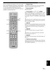
... ( / ) to change the preset station number (1 to 54). INTRODUCTION This section describes the functions of this unit. Note that the Radio Data System controls are available for Australia model only. 1 2 3 4 STANDBY/ON POWER POWER AV TV DVD AUX1 AUX2 AUX3 TV INPUT1 MACRO STB TV PRESET... to E) (see pages 52 and 53). DECODE 0 +10 ENHANCER ENTRY MENU A-E DISPLAY ENTER TV/AV YSP RETURN VOLUME CH TV VOL 5 6 7 MUTE TV INPUT TV MUTE CH LEVEL TEST CODE SET Controls and functions 1 PRESET/TUNE FM: Switches between automatic and manual tuning (see page 51). 7 Operation...
... ( / ) to change the preset station number (1 to 54). INTRODUCTION This section describes the functions of this unit. Note that the Radio Data System controls are available for Australia model only. 1 2 3 4 STANDBY/ON POWER POWER AV TV DVD AUX1 AUX2 AUX3 TV INPUT1 MACRO STB TV PRESET... to E) (see pages 52 and 53). DECODE 0 +10 ENHANCER ENTRY MENU A-E DISPLAY ENTER TV/AV YSP RETURN VOLUME CH TV VOL 5 6 7 MUTE TV INPUT TV MUTE CH LEVEL TEST CODE SET Controls and functions 1 PRESET/TUNE FM: Switches between automatic and manual tuning (see page 51). 7 Operation...
Owner's Manual
Page 18
... between the input source on your TV (see page 91). DECODE 0 +10 ENHANCER ENTRY MENU CAT/ A-E DISPLAY ENTER TV/AV YSP RETURN VOLUME CH TV VOL MUTE TV INPUT TV MUTE CODE SET CH LEVEL TEST G H I * * J* K L M N O P Q R S t U* V W * * 1 Infrared window Outputs infrared control signals. Increases or... program buttons Select the sound field programs (see page 65). 8 ENHANCER Turns on or off the Music Enhancer (see page 49). See "Controlling other components using the remote control once you want to operate. 2 STANDBY/ON Sets this system to the standby mode (see page 33)....
... between the input source on your TV (see page 91). DECODE 0 +10 ENHANCER ENTRY MENU CAT/ A-E DISPLAY ENTER TV/AV YSP RETURN VOLUME CH TV VOL MUTE TV INPUT TV MUTE CODE SET CH LEVEL TEST G H I * * J* K L M N O P Q R S t U* V W * * 1 Infrared window Outputs infrared control signals. Increases or... program buttons Select the sound field programs (see page 65). 8 ENHANCER Turns on or off the Music Enhancer (see page 49). See "Controlling other components using the remote control once you want to operate. 2 STANDBY/ON Sets this system to the standby mode (see page 33)....
Owner's Manual
Page 19
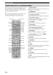
... O INPUTMODE Toggles between input modes (AUTO, DTS, and ANALOG) (see pages 56, 62, and 63). P Beam mode buttons Change the beam mode settings (see page 93). Q SUR. Select YSP when operating this unit and select TV/AV when operating your DVD player or VCR (see pages 105 and 106). V CH +/- Note The... TV monitor (see page 104). Sets up remote control codes (see page 63). J INPUT1 Switches the input source on the power of your TV (see pages 39 and 77). Adjusts the volume level of your TV (see page 54). Changes the channels of your TV, digital satellite tuner, cable TV tuner, ...
... O INPUTMODE Toggles between input modes (AUTO, DTS, and ANALOG) (see pages 56, 62, and 63). P Beam mode buttons Change the beam mode settings (see page 93). Q SUR. Select YSP when operating this unit and select TV/AV when operating your DVD player or VCR (see pages 105 and 106). V CH +/- Note The... TV monitor (see page 104). Sets up remote control codes (see page 63). J INPUT1 Switches the input source on the power of your TV (see pages 39 and 77). Adjusts the volume level of your TV (see page 54). Changes the channels of your TV, digital satellite tuner, cable TV tuner, ...

Owner's Manual
Page 20
DECODE 0 +10 ENHANCER ENTRY MENU CAT/ A-E DISPLAY ENTER TV/AV YSP RETURN VOLUME CH TV VOL 5 6 7 MUTE TV INPUT TV MUTE CODE SET CH LEVEL TEST 1 PRESET/TUNE FM: Switches between the preset search mode and the frequency search mode (see pages 51 to 54). 2 Numeric buttons FM, ... Preset Search) (see pages 53 and 54). Use ENTER to E) (see pages 7 and 8 in Preset Search mode. XM: Use to confirm the input above . Select YSP when operating this unit is receiving an XM channel (see page 10 in the Reference Guide) or playing back your iPod (see page 9 in the...
DECODE 0 +10 ENHANCER ENTRY MENU CAT/ A-E DISPLAY ENTER TV/AV YSP RETURN VOLUME CH TV VOL 5 6 7 MUTE TV INPUT TV MUTE CODE SET CH LEVEL TEST 1 PRESET/TUNE FM: Switches between the preset search mode and the frequency search mode (see pages 51 to 54). 2 Numeric buttons FM, ... Preset Search) (see pages 53 and 54). Use ENTER to E) (see pages 7 and 8 in Preset Search mode. XM: Use to confirm the input above . Select YSP when operating this unit is receiving an XM channel (see page 10 in the Reference Guide) or playing back your iPod (see page 9 in the...
Owner's Manual
Page 24
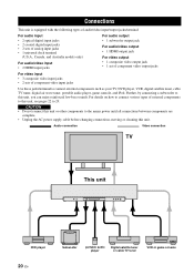
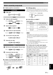
..., moving or cleaning this unit, you can enjoy reinforced low-bass sounds. Connections Connections This unit is equipped with the following types of audio/video input/output jacks/terminal: For audio input • 2 optical digital input jacks • 2 coaxial digital input jacks • 2 sets of analog input jacks • 1 universal dock terminal (U.S.A., Canada, and...
..., moving or cleaning this unit, you can enjoy reinforced low-bass sounds. Connections Connections This unit is equipped with the following types of audio/video input/output jacks/terminal: For audio input • 2 optical digital input jacks • 2 coaxial digital input jacks • 2 sets of analog input jacks • 1 universal dock terminal (U.S.A., Canada, and...
Owner's Manual
Page 25
...; Affixing cables To prevent cables from a single source component, this unit plays back the audio signals in the following priority order: HDMI → Digital → Analog As default settings, the following input jacks are assigned to the rear panel of audio signals are simultaneously being input from becoming unplugged, place the supplied...
...; Affixing cables To prevent cables from a single source component, this unit plays back the audio signals in the following priority order: HDMI → Digital → Analog As default settings, the following input jacks are assigned to the rear panel of audio signals are simultaneously being input from becoming unplugged, place the supplied...
Owner's Manual
Page 27
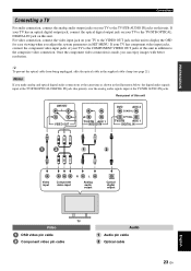
...video connection. If your TV has an optical digital output jack, connect the optical digital output jack on your TV to the COMPONENT...system parameters in the supplied cable clamp (see page 21). Notes If you can enjoy images with better resolution. Rear panel of your TV to the TV/STB OPTICAL DIGITAL... IN jack on this unit in the illustration below, the digital audio signals input at the TV/STB OPTICAL DIGITAL IN ... COAXIAL OPTICAL TV/STB AUX 1 DIGITAL IN Video input R L Component video input Analog audio output Optical digital output TV Video OSD video pin ...
...video connection. If your TV has an optical digital output jack, connect the optical digital output jack on your TV to the COMPONENT...system parameters in the supplied cable clamp (see page 21). Notes If you can enjoy images with better resolution. Rear panel of your TV to the TV/STB OPTICAL DIGITAL... IN jack on this unit in the illustration below, the digital audio signals input at the TV/STB OPTICAL DIGITAL IN ... COAXIAL OPTICAL TV/STB AUX 1 DIGITAL IN Video input R L Component video input Analog audio output Optical digital output TV Video OSD video pin ...
Owner's Manual
Page 28
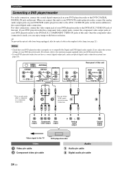
...For details, refer to the operation manual supplied with better resolution. Once the component video connection is properly set to output Dolby Digital and DTS digital audio signals. If not, adjust the system settings of your DVD player/recorder to the DVD/AUX 2 VIDEO IN jack of this unit DVD AUX ...2 COAXIAL OPTICAL TV/STB AUX 1 DIGITAL IN *1You can enjoy images with your DVD player/recorder. • If ...
...For details, refer to the operation manual supplied with better resolution. Once the component video connection is properly set to output Dolby Digital and DTS digital audio signals. If not, adjust the system settings of your DVD player/recorder to the DVD/AUX 2 VIDEO IN jack of this unit DVD AUX ...2 COAXIAL OPTICAL TV/STB AUX 1 DIGITAL IN *1You can enjoy images with your DVD player/recorder. • If ...

Owner's Manual
Page 33
... and then run AUTO SETUP (see page 37) or select SWFR for BASS OUT in SUBWOOFER SET (see page 82). If the subwoofer is connected using a system type connection, changing the power mode of this unit controls the power mode of this unit (U.S.A.... Yamaha subwoofer equipped with a SYSTEM CONNECTOR terminal, connect it to the SUBWOOFER jack on this unit. ANTENNA COMPONENT COMPONENT SUBWOOFER SYSTEM CONNECTOR VIDEO OUT STB DVD/AUX 2 VIDEO IN AUX 1 System connector 5 cable System Monaural connector input Audio 5 Subwoofer pin cable Subwoofer English 29 En To output sound from...
... and then run AUTO SETUP (see page 37) or select SWFR for BASS OUT in SUBWOOFER SET (see page 82). If the subwoofer is connected using a system type connection, changing the power mode of this unit controls the power mode of this unit (U.S.A.... Yamaha subwoofer equipped with a SYSTEM CONNECTOR terminal, connect it to the SUBWOOFER jack on this unit. ANTENNA COMPONENT COMPONENT SUBWOOFER SYSTEM CONNECTOR VIDEO OUT STB DVD/AUX 2 VIDEO IN AUX 1 System connector 5 cable System Monaural connector input Audio 5 Subwoofer pin cable Subwoofer English 29 En To output sound from...
Owner's Manual
Page 36
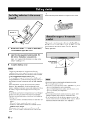
... during operation. 2 Insert the two supplied batteries (AA, R6, UM-3) into contact with clothing, etc. The remote control is unwantedly erased, insert new batteries and set the remote control codes again. If the batteries have the same shape and color. • Exhausted batteries may have leaked, dispose of batteries (such as...
... during operation. 2 Insert the two supplied batteries (AA, R6, UM-3) into contact with clothing, etc. The remote control is unwantedly erased, insert new batteries and set the remote control codes again. If the batteries have the same shape and color. • Exhausted batteries may have leaked, dispose of batteries (such as...

Owner's Manual
Page 37
... PRESET/TUNE SEARCH MEMORY FM/XM CAT (U.S.A. and Canada models) 1 Press STANDBY/ON to turn on this unit or setting it to the standby mode Getting started 2 Press STANDBY/ON again to set this unit to the standby mode. Turning on the power of this unit is operational, and the other control...
... PRESET/TUNE SEARCH MEMORY FM/XM CAT (U.S.A. and Canada models) 1 Press STANDBY/ON to turn on this unit or setting it to the standby mode Getting started 2 Press STANDBY/ON again to set this unit to the standby mode. Turning on the power of this unit is operational, and the other control...


