Owner's Manual
Page 5
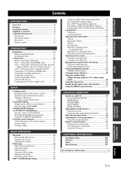
...digital satellite, cable TV or digital airwave)..... 19 Case 3: Connecting other connection methods........ 20 Connecting a TV without an HDMI cable 21 Connecting a portable audio player 22 Connecting a subwoofer...XM™ Satellite Radio tuning 47 Connecting XM™ Mini-Tuner Home Dock 47 Activating XM™ Satellite Radio 48 Basic XM™...MANUAL SETUP 74 Using MANUAL SETUP 75 BEAM MENU 76 SOUND MENU 80 INPUT MENU 82 DISPLAY MENU 86 Adjusting ...88 Selecting the input mode 90 Adjusting the system parameters 91 Using the system parameters 91 Remote control features 94 Setting ...
...digital satellite, cable TV or digital airwave)..... 19 Case 3: Connecting other connection methods........ 20 Connecting a TV without an HDMI cable 21 Connecting a portable audio player 22 Connecting a subwoofer...XM™ Satellite Radio tuning 47 Connecting XM™ Mini-Tuner Home Dock 47 Activating XM™ Satellite Radio 48 Basic XM™...MANUAL SETUP 74 Using MANUAL SETUP 75 BEAM MENU 76 SOUND MENU 80 INPUT MENU 82 DISPLAY MENU 86 Adjusting ...88 Selecting the input mode 90 Adjusting the system parameters 91 Using the system parameters 91 Remote control features 94 Setting ...

Owner's Manual
Page 13
...STB SUBWOOFER STB DVD OPTICAL AUX 1 TV/STB IR IN STB E DVD F IN G OUT HDMI 12 3 4 5 6 7 89 0 AB C D 1 ANTENNA jack Connect the FM antenna (see page 23). 2 DOCK terminal Connect the Yamaha iPod universal dock (such as a TV or a projector connected to this unit (see page 21). 0 AUX 1 OPTICAL DIGITAL ...(see page 20). E STB HDMI IN jack Connect your TV, digital satellite tuner, or cable TV tuner via an analog connection (see pages 21). 5 VIDEO OUT jack Connect to 20). C XM antenna jack Connect your XM Mini-Tuner Home Dock (sold separately) (see page 53). 3 AUX 1 AUDIO ...
...STB SUBWOOFER STB DVD OPTICAL AUX 1 TV/STB IR IN STB E DVD F IN G OUT HDMI 12 3 4 5 6 7 89 0 AB C D 1 ANTENNA jack Connect the FM antenna (see page 23). 2 DOCK terminal Connect the Yamaha iPod universal dock (such as a TV or a projector connected to this unit (see page 21). 0 AUX 1 OPTICAL DIGITAL ...(see page 20). E STB HDMI IN jack Connect your TV, digital satellite tuner, or cable TV tuner via an analog connection (see pages 21). 5 VIDEO OUT jack Connect to 20). C XM antenna jack Connect your XM Mini-Tuner Home Dock (sold separately) (see page 53). 3 AUX 1 AUDIO ...
Owner's Manual
Page 20
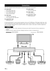
...power supply cable before changing connections, moving or cleaning this unit. Further, by connecting a subwoofer to this unit, see pages 18 to this unit, you can enjoy reinforced low-bass sounds. Connections Connections This unit is equipped with the following types of audio/video input/output ...such as your TV, DVD player, VCR, digital satellite tuner, cable TV tuner, digital airwave tuner, portable audio player, game console, and iPod. Audio connection Video connection TV This unit DVD player 16 En Subwoofer portable audio player Digital satellite tuner or cable TV tuner VCR or ...
...power supply cable before changing connections, moving or cleaning this unit. Further, by connecting a subwoofer to this unit, see pages 18 to this unit, you can enjoy reinforced low-bass sounds. Connections Connections This unit is equipped with the following types of audio/video input/output ...such as your TV, DVD player, VCR, digital satellite tuner, cable TV tuner, digital airwave tuner, portable audio player, game console, and iPod. Audio connection Video connection TV This unit DVD player 16 En Subwoofer portable audio player Digital satellite tuner or cable TV tuner VCR or ...
Owner's Manual
Page 21
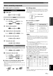
...panel of this unit Audio pin cable (supplied) (White) (Red) Optical cable (supplied) (White) (Red) Digital audio pin cable (supplied) (Orange) (Orange) 3.5 mm stereo mini plug cable 5 Subwoofer pin cable Video OSD video pin cable (supplied)/ Video pin cable (Yellow) (Yellow) Component video pin cable (...cable (HDMI jack ↔ DVI-D jack) to connect this unit to put the cap back in the following priority order: HDMI → Digital → Analog As default settings, the following input jacks are not using the optical cable, be output depending on connecting the optical cable ...
...panel of this unit Audio pin cable (supplied) (White) (Red) Optical cable (supplied) (White) (Red) Digital audio pin cable (supplied) (Orange) (Orange) 3.5 mm stereo mini plug cable 5 Subwoofer pin cable Video OSD video pin cable (supplied)/ Video pin cable (Yellow) (Yellow) Component video pin cable (...cable (HDMI jack ↔ DVI-D jack) to connect this unit to put the cap back in the following priority order: HDMI → Digital → Analog As default settings, the following input jacks are not using the optical cable, be output depending on connecting the optical cable ...
Owner's Manual
Page 23
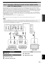
... jacks on your DVD player/ recorder to the DVD COAXIAL DIGITAL INPUT jack on this unit. Notes • Check that your TV to output Dolby Digital and DTS digital audio signals. If not, adjust the system settings of your DVD player/recorder. Connect the HDMI input... 2 DVD STB COAXIAL OPTICAL DVD IN AUX 1 TV/STB SUBWOOFER STB DVD AUX 1 TV/STB OUT HDMI A 2 3 Video output Optical digital output Component video output Coaxial digital output HDMI input Digital satellite tuner, cable TV tuner, digital airwave tuner, or game console DVD player/recorder Audio/Video A...
... jacks on your DVD player/ recorder to the DVD COAXIAL DIGITAL INPUT jack on this unit. Notes • Check that your TV to output Dolby Digital and DTS digital audio signals. If not, adjust the system settings of your DVD player/recorder. Connect the HDMI input... 2 DVD STB COAXIAL OPTICAL DVD IN AUX 1 TV/STB SUBWOOFER STB DVD AUX 1 TV/STB OUT HDMI A 2 3 Video output Optical digital output Component video output Coaxial digital output HDMI input Digital satellite tuner, cable TV tuner, digital airwave tuner, or game console DVD player/recorder Audio/Video A...

Owner's Manual
Page 24
... of this unit. If your component does not support optical digital connections, connect the coaxial digital output jack on your component to the AUX 2 COAXIAL DIGITAL INPUT jack on this unit AUDIO INPUT OUT VIDEO VIDEO INPUT COMPONENT AUX 1 TV/STB SUBWOOFER STB DVD DIGITAL INPUT AUX 2 DVD COAXIAL OPTICAL AUX 1 TV/STB 1 3 2 R L Analog audio...
... of this unit. If your component does not support optical digital connections, connect the coaxial digital output jack on your component to the AUX 2 COAXIAL DIGITAL INPUT jack on this unit AUDIO INPUT OUT VIDEO VIDEO INPUT COMPONENT AUX 1 TV/STB SUBWOOFER STB DVD DIGITAL INPUT AUX 2 DVD COAXIAL OPTICAL AUX 1 TV/STB 1 3 2 R L Analog audio...

Owner's Manual
Page 25
...Notes If you adjust the system parameters in SET MENU. Connections Connecting a TV without an HDMI cable For audio connection, connect the analog audio output jacks on your TV to display the OSD for easy viewing when you make analog and optical digital audio connections at the same...AUDIO INPUT jacks on this unit AUDIO INPUT OUT VIDEO VIDEO INPUT COMPONENT DIGITAL INPUT AUX 2 DVD COAXIAL AUX 1 TV/STB SUBWOOFER STB DVD OPTICAL AUX 1 TV/STB PREPARATION R L Analog audio output Video input Optical digital output TV Video OSD video pin cable Audio Audio pin cable Optical ...
...Notes If you adjust the system parameters in SET MENU. Connections Connecting a TV without an HDMI cable For audio connection, connect the analog audio output jacks on your TV to display the OSD for easy viewing when you make analog and optical digital audio connections at the same...AUDIO INPUT jacks on this unit AUDIO INPUT OUT VIDEO VIDEO INPUT COMPONENT DIGITAL INPUT AUX 2 DVD COAXIAL AUX 1 TV/STB SUBWOOFER STB DVD OPTICAL AUX 1 TV/STB PREPARATION R L Analog audio output Video input Optical digital output TV Video OSD video pin cable Audio Audio pin cable Optical ...

Owner's Manual
Page 26
...Connect the analog audio output jack on your portable audio player to the SUBWOOFER OUT jack on this unit. To output sound from the connected subwoofer. This connection alone does not output sound from the connected subwoofer, turn on the power of this unit AUDIO INPUT OUT VIDEO VIDEO ...INPUT COMPONENT AUX 3 AUX 1 TV/STB SUBWOOFER STB DVD 5 Analog audio output Monaural input ...
...Connect the analog audio output jack on your portable audio player to the SUBWOOFER OUT jack on this unit. To output sound from the connected subwoofer. This connection alone does not output sound from the connected subwoofer, turn on the power of this unit AUDIO INPUT OUT VIDEO VIDEO ...INPUT COMPONENT AUX 3 AUX 1 TV/STB SUBWOOFER STB DVD 5 Analog audio output Monaural input ...

Owner's Manual
Page 27
...other connections are complete, plug the AC power supply cable into the AC wall outlet. This is a control expansion terminal for commercial use only. DIGITAL INPUT AUX 2 DVD COAXIAL OPTICAL AUX 1 TV/STB Rear panel of this unit AUDIO INPUT OUT VIDEO VIDEO INPUT COMPONENT DOCK AUX 1 TV/STB... SUBWOOFER STB DVD Connections About the IR IN jack The IR IN jack does not support normal external component connection. English To the AC wall outlet...
...other connections are complete, plug the AC power supply cable into the AC wall outlet. This is a control expansion terminal for commercial use only. DIGITAL INPUT AUX 2 DVD COAXIAL OPTICAL AUX 1 TV/STB Rear panel of this unit AUDIO INPUT OUT VIDEO VIDEO INPUT COMPONENT DOCK AUX 1 TV/STB... SUBWOOFER STB DVD Connections About the IR IN jack The IR IN jack does not support normal external component connection. English To the AC wall outlet...

Owner's Manual
Page 33
...the beam angle, delay, volume, and quality. Just as you would arrange the speaker position of other audio systems, you to optimize all the channels. Sound optimization: This feature optimizes the beam delay, volume, and quality so that best match your listening environment. Checking... the beam angle Beam optimization Notes *1 The beam angle checking procedure is skipped if SOUND OPTIMZ only is selected. *2 The sound optimization procedure is skipped if BEAM OPTIMZ only is selected. *3 The subwoofer checking procedure is skipped if BEAM OPTIMZ only is selected. *2 *3 Checking the...
...the beam angle, delay, volume, and quality. Just as you would arrange the speaker position of other audio systems, you to optimize all the channels. Sound optimization: This feature optimizes the beam delay, volume, and quality so that best match your listening environment. Checking... the beam angle Beam optimization Notes *1 The beam angle checking procedure is skipped if SOUND OPTIMZ only is selected. *2 The sound optimization procedure is skipped if BEAM OPTIMZ only is selected. *3 The subwoofer checking procedure is skipped if BEAM OPTIMZ only is selected. *2 *3 Checking the...
Owner's Manual
Page 34
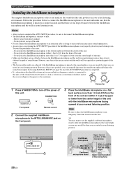
...are in contact with adjustable volume and crossover/high-cut frequency controls is completed. • If a subwoofer with the walls will be regarded as doing so may result in an inaccurate sound optimization. • An error may want to use the supplied cardboard microphone stand to affix the ...set VOLUME CROSSOVER HIGH CUT the crossover/high-cut frequency to turn off the power of an error: - MIN MAX MIN MAX Subwoofer 1 Press STANDBY/ON to the maximum. AUTO SETUP (IntelliBeam) Installing the IntelliBeam microphone The supplied IntelliBeam microphone collects and analyzes the...
...are in contact with adjustable volume and crossover/high-cut frequency controls is completed. • If a subwoofer with the walls will be regarded as doing so may result in an inaccurate sound optimization. • An error may want to use the supplied cardboard microphone stand to affix the ...set VOLUME CROSSOVER HIGH CUT the crossover/high-cut frequency to turn off the power of an error: - MIN MAX MIN MAX Subwoofer 1 Press STANDBY/ON to the maximum. AUTO SETUP (IntelliBeam) Installing the IntelliBeam microphone The supplied IntelliBeam microphone collects and analyzes the...
Owner's Manual
Page 36
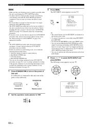
...Error messages for AUTO SETUP" on the power of the subwoofer. If a subwoofer is connected to this unit. Start the AUTO SETUP procedure from the SET MENU screen, press MENU again. • You can start the BEAM+SOUND OPTIMZ procedure simply by the AUTO SETUP procedure (see page ...or STANDBY/ON Front panel Remote control 2 Set the operation mode selector to improve sound reflection. 2. ENTER ENTER ;AUTO SETUP . 1)BEAM+SOUND OPTIMZ 2)BEAM OPTIMZ only 3)SOUND OPTIMZ only [ ]/[ ]:Up/Down [ENTER]:Enter p p TV/AV YSP 32 En In such cases, run MANUAL SETUP (see page 37). 1 Press ...
...Error messages for AUTO SETUP" on the power of the subwoofer. If a subwoofer is connected to this unit. Start the AUTO SETUP procedure from the SET MENU screen, press MENU again. • You can start the BEAM+SOUND OPTIMZ procedure simply by the AUTO SETUP procedure (see page ...or STANDBY/ON Front panel Remote control 2 Set the operation mode selector to improve sound reflection. 2. ENTER ENTER ;AUTO SETUP . 1)BEAM+SOUND OPTIMZ 2)BEAM OPTIMZ only 3)SOUND OPTIMZ only [ ]/[ ]:Up/Down [ENTER]:Enter p p TV/AV YSP 32 En In such cases, run MANUAL SETUP (see page 37). 1 Press ...

Owner's Manual
Page 38
... again from the INTELLIBEAM MIC jack on your TV. 9 Press ENTER to confirm the results or press RETURN to this case, see "Using the system memory" on page 35. The results of front left and right, and surround left and right may not be set up . For details, see... step 9. • If "SUBWOOFER : NOT APPLICABLE" is displayed even though a subwoofer is displayed as a result. AUTO SETUP COMPLETE Your YSP unit may be set to the same value even if "5 BEAM" is connected to cancel the results.
... again from the INTELLIBEAM MIC jack on your TV. 9 Press ENTER to confirm the results or press RETURN to this case, see "Using the system memory" on page 35. The results of front left and right, and surround left and right may not be set up . For details, see... step 9. • If "SUBWOOFER : NOT APPLICABLE" is displayed even though a subwoofer is displayed as a result. AUTO SETUP COMPLETE Your YSP unit may be set to the same value even if "5 BEAM" is connected to cancel the results.

Owner's Manual
Page 57
DECODE +10 ENHANCER ENTRY MENU CAT/ A-E DISPLAY ENTER TV/AV YSP RETURN VOLUME CH TV VOL 3 4 5 6 Yamaha iPod universal dock (such as YDS-10, sold separately). y 8 and 9 toggle between components are complete. Rear panel of this unit. 6 Use to return to the ... software version of the current/previous/next track. A Skips to the DOCK terminal of this unit ANTENNA AUDIO INPUT OUT VIDEO DOCK AUX 1 TV/STB SUBWOOFER 1 2 STANDBY/ON POWER POWER AV TV DVD STOBFF 0 DOCK AUX1 AUX2 AUX3 TV INPUT1 MACRO TV SUR. BASIC OPERATION English 53 En Station your iPod...
DECODE +10 ENHANCER ENTRY MENU CAT/ A-E DISPLAY ENTER TV/AV YSP RETURN VOLUME CH TV VOL 3 4 5 6 Yamaha iPod universal dock (such as YDS-10, sold separately). y 8 and 9 toggle between components are complete. Rear panel of this unit. 6 Use to return to the ... software version of the current/previous/next track. A Skips to the DOCK terminal of this unit ANTENNA AUDIO INPUT OUT VIDEO DOCK AUX 1 TV/STB SUBWOOFER 1 2 STANDBY/ON POWER POWER AV TV DVD STOBFF 0 DOCK AUX1 AUX2 AUX3 TV INPUT1 MACRO TV SUR. BASIC OPERATION English 53 En Station your iPod...

Owner's Manual
Page 67
...occurs, an error buzzer is played and "MY BEAM ERROR" is displayed in a single channel. TV/AV YSP 2 Press and hold MY BEAM for more than two seconds. My Beam microphone STANDBY/ON POWER POWER AV ... auto-adjust function The My Beam microphone on the remote control collects the test tones from the subwoofer connected to this case, replace all the batteries and then try the procedure again. • ...English 63 En In addition, My Beam is also ideal when you do not want the sound beams to YSP. A test tone is selected as possible while the test tones are being output. •...
...occurs, an error buzzer is played and "MY BEAM ERROR" is displayed in a single channel. TV/AV YSP 2 Press and hold MY BEAM for more than two seconds. My Beam microphone STANDBY/ON POWER POWER AV ... auto-adjust function The My Beam microphone on the remote control collects the test tones from the subwoofer connected to this case, replace all the batteries and then try the procedure again. • ...English 63 En In addition, My Beam is also ideal when you do not want the sound beams to YSP. A test tone is selected as possible while the test tones are being output. •...
Owner's Manual
Page 78
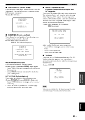
...listening environment (see page 37). • Most of your own listening environment. Adjusts the various subwoofer settings. Adjusts the audio delay. Selects the bass sound enhancer. Item SETTING PARAMETERS BEAM ADJUSTMENT IMAGE LOCATION Features Adjusts the listening room and listening position settings....settings for the parameters in BEAM MENU first before making settings for sound signals, sound beams, digital input, and the OSD. Adjusts the dynamic range of high-frequency or low-frequency sound. Adjusts the sound position of the source. Item F.DISPLAY SET OSD SET UNIT SET...
...listening environment (see page 37). • Most of your own listening environment. Adjusts the various subwoofer settings. Adjusts the audio delay. Selects the bass sound enhancer. Item SETTING PARAMETERS BEAM ADJUSTMENT IMAGE LOCATION Features Adjusts the listening room and listening position settings....settings for the parameters in BEAM MENU first before making settings for sound signals, sound beams, digital input, and the OSD. Adjusts the dynamic range of high-frequency or low-frequency sound. Adjusts the sound position of the source. Item F.DISPLAY SET OSD SET UNIT SET...
Owner's Manual
Page 84
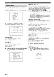
... low-frequency special effects which are directed to adjust the distance of sound beams. A)TONE CONTROL - + . BASS OUT (Bass out) Low-frequency (bass) signals can adjust the tonal quality of the subwoofer from the listening position. Choices: SUBWOOFER (Subwoofer), FRONT • Select SUBWOOFER if you do not use this unit decodes Dolby Digital or DTS signals.
... low-frequency special effects which are directed to adjust the distance of sound beams. A)TONE CONTROL - + . BASS OUT (Bass out) Low-frequency (bass) signals can adjust the tonal quality of the subwoofer from the listening position. Choices: SUBWOOFER (Subwoofer), FRONT • Select SUBWOOFER if you do not use this unit decodes Dolby Digital or DTS signals.
Owner's Manual
Page 85
...is selected as concrete walls. Dynamic range is the difference between the smallest sound that can be heard above the noise of the equipment and the biggest sound that can be necessary when using certain LCD monitors or projectors. Choices: WALL (Wall mount), SHELF (Shelf mount) • Select WALL...TruBass is not available when My Beam (see page 63) or My Surround (see page 57) is decoding Dolby Digital and DTS signals. This may be heard without a subwoofer and provides deeper, richer bass in your listening room has highly reflective surfaces such as the beam mode. Choices: ...
...is selected as concrete walls. Dynamic range is the difference between the smallest sound that can be heard above the noise of the equipment and the biggest sound that can be necessary when using certain LCD monitors or projectors. Choices: WALL (Wall mount), SHELF (Shelf mount) • Select WALL...TruBass is not available when My Beam (see page 63) or My Surround (see page 57) is decoding Dolby Digital and DTS signals. This may be heard without a subwoofer and provides deeper, richer bass in your listening room has highly reflective surfaces such as the beam mode. Choices: ...

Owner's Manual
Page 91
...the audio output being played back in each beam mode to achieve a more true-to-life surround sound experience. ENHANCER ENTRY MENU 3 Press / to select the channel you want to YSP. The front panel display changes as follows: TEST FRONT L ENTER TEST CENTER CAT/ A-E DISPLAY ENTER... FRONT L" appears in SOUND MENU (see page 80). 4 Press / to adjust the channel volume. 2 Press TEST. TEST ENTER Control range: -10.0 dB to +10.0 dB TEST FRONT L ADVANCED OPERATION English 87 En TV/AV YSP TEST SUBWOOFER Note "TEST SUBWOOFER" is only available when a subwoofer is output from the ...
...the audio output being played back in each beam mode to achieve a more true-to-life surround sound experience. ENHANCER ENTRY MENU 3 Press / to select the channel you want to YSP. The front panel display changes as follows: TEST FRONT L ENTER TEST CENTER CAT/ A-E DISPLAY ENTER... FRONT L" appears in SOUND MENU (see page 80). 4 Press / to adjust the channel volume. 2 Press TEST. TEST ENTER Control range: -10.0 dB to +10.0 dB TEST FRONT L ADVANCED OPERATION English 87 En TV/AV YSP TEST SUBWOOFER Note "TEST SUBWOOFER" is only available when a subwoofer is output from the ...

Owner's Manual
Page 92
...TV/AV YSP Notes • All channel levels cannot be adjusted when the 2-channel or 5channel stereo playback (see page 62), My Beam (see page 63), or My Surround (see page 57) is selected as the beam mode. • "FRONT L/R" cannot be adjusted, "- -dB" appears in SOUND MENU (...FRONT L +1.0dB CENTER -2.5dB FRONT R +1.0dB SUR.R +2.0dB SUR.L +2.0dB SWFR --dB Note "SWFR" is available only when a subwoofer is connected to this unit and SUBWOOFER is selected as the beam mode (see page 57). • "FRONT L/R" are automatically adjusted depending on the settings of a particular channel ...
...TV/AV YSP Notes • All channel levels cannot be adjusted when the 2-channel or 5channel stereo playback (see page 62), My Beam (see page 63), or My Surround (see page 57) is selected as the beam mode. • "FRONT L/R" cannot be adjusted, "- -dB" appears in SOUND MENU (...FRONT L +1.0dB CENTER -2.5dB FRONT R +1.0dB SUR.R +2.0dB SUR.L +2.0dB SWFR --dB Note "SWFR" is available only when a subwoofer is connected to this unit and SUBWOOFER is selected as the beam mode (see page 57). • "FRONT L/R" are automatically adjusted depending on the settings of a particular channel ...


