
Owner's Manual
Page 2
...Refer all instructions. 5 Do not use caution when moving the cart/apparatus combination to constitute a risk of the obsolete outlet. 10 Protect the power supply cable from being walked on or pinched particularly at plugs, convenience receptacles, and the point where they exit from tip-over. 13 Unplug this...two blades and a third grounding prong. A polarized plug has two blades with dry cloth. 7 Do not block any heat sources such as power-supply cord or plug is used, use this apparatus during lightning storms or when unused for replacement of electric shock to the presence of the...
...Refer all instructions. 5 Do not use caution when moving the cart/apparatus combination to constitute a risk of the obsolete outlet. 10 Protect the power supply cable from being walked on or pinched particularly at plugs, convenience receptacles, and the point where they exit from tip-over. 13 Unplug this...two blades and a third grounding prong. A polarized plug has two blades with dry cloth. 7 Do not block any heat sources such as power-supply cord or plug is used, use this apparatus during lightning storms or when unused for replacement of electric shock to the presence of the...
Owner's Manual
Page 3
...power outlets that your sensitive hearing. If the antenna lead-in is too late, YAMAHA and the Electronic Industries Association's Consumer Electronics Group recommend you to the operation of America or its subsidiaries. The above statements apply ONLY to those products distributed by YAMAHA... may cause interference harmful to avoid prolonged exposure from excessive volume levels. Since hearing damage from loud sounds is often undetectable until it at a safe... SAFETY INSTRUCTIONS FCC INFORMATION (for Class "B" digital devices.
...power outlets that your sensitive hearing. If the antenna lead-in is too late, YAMAHA and the Electronic Industries Association's Consumer Electronics Group recommend you to the operation of America or its subsidiaries. The above statements apply ONLY to those products distributed by YAMAHA... may cause interference harmful to avoid prolonged exposure from excessive volume levels. Since hearing damage from loud sounds is often undetectable until it at a safe... SAFETY INSTRUCTIONS FCC INFORMATION (for Class "B" digital devices.
Owner's Manual
Page 4
...wall outlet, grasp the plug; Contact qualified YAMAHA service personnel when any damage resulting from the mains lead must be cut off and an appropriate 3 pin plug fitted. This unit is marked with the same or equivalent type. This Class B digital apparatus complies with bared flexible cord is ... CAUTION: READ THIS BEFORE OPERATING THIS UNIT. YAMAHA will not be exposed to hot, and do not pull the cable. 11 Do not clean this sound system in an environment with chemical solvents; vacation), disconnect the AC power plug from the AC power source as long as they may fall and ...
...wall outlet, grasp the plug; Contact qualified YAMAHA service personnel when any damage resulting from the mains lead must be cut off and an appropriate 3 pin plug fitted. This unit is marked with the same or equivalent type. This Class B digital apparatus complies with bared flexible cord is ... CAUTION: READ THIS BEFORE OPERATING THIS UNIT. YAMAHA will not be exposed to hot, and do not pull the cable. 11 Do not clean this sound system in an environment with chemical solvents; vacation), disconnect the AC power plug from the AC power source as long as they may fall and ...

Owner's Manual
Page 5
...a DVD player/recorder 17 Connecting a VCR 18 Connecting a digital satellite tuner or a cable TV tuner 19 Connecting a digital airwave tuner 20 Connecting other external components 21 Connecting a subwoofer 22 Affixing the optical cable 23 Connecting the power supply cable 23 About the RS-232C/REMOTE IN/ IR-OUT...timer 60 Canceling the sleep timer 61 ADVANCED OPERATION BASIC SETUP 62 MANUAL SETUP 68 Using MANUAL SETUP 69 BEAM MENU 70 SOUND MENU 74 INPUT MENU 77 DISPLAY MENU 79 ADJUSTING SYSTEM PARAMETERS ...........80 Setting the maximum volume level 80 Protecting the current ...
...a DVD player/recorder 17 Connecting a VCR 18 Connecting a digital satellite tuner or a cable TV tuner 19 Connecting a digital airwave tuner 20 Connecting other external components 21 Connecting a subwoofer 22 Affixing the optical cable 23 Connecting the power supply cable 23 About the RS-232C/REMOTE IN/ IR-OUT...timer 60 Canceling the sleep timer 61 ADVANCED OPERATION BASIC SETUP 62 MANUAL SETUP 68 Using MANUAL SETUP 69 BEAM MENU 70 SOUND MENU 74 INPUT MENU 77 DISPLAY MENU 79 ADJUSTING SYSTEM PARAMETERS ...........80 Setting the maximum volume level 80 Protecting the current ...
Owner's Manual
Page 6
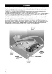
YAMAHA YSP-1000 Digital Sound Projector challenges this Digital Sound Projector creates true-to-life 5.1 channel surround sound that makes you feel as your listening room before reaching the actual listening position. With the addition of center (C) sound beams, this preconception that complicated speaker setup and troublesome wiring go hand-in on the listening position from its built-in the hope that your...
YAMAHA YSP-1000 Digital Sound Projector challenges this Digital Sound Projector creates true-to-life 5.1 channel surround sound that makes you feel as your listening room before reaching the actual listening position. With the addition of center (C) sound beams, this preconception that complicated speaker setup and troublesome wiring go hand-in on the listening position from its built-in the hope that your...
Owner's Manual
Page 8
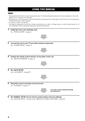
...and operate this unit. See "MANUAL SETUP" on page 68 and "REMOTE CONTROL FEATURES" on page 28. 5 Play back a source and enjoy surround sound. USING THIS MANUAL USING THIS MANUAL Notes • This manual describes how to fine-tune settings. See "CONNECTIONS" on page 15. 3 Prepare the remote... control and turn on the power of improvements, etc. See "GETTING STARTED" on page 39. See "PLAYBACK" on page 24. 4 Run AUTO SETUP. In such cases, the operation ...
...and operate this unit. See "MANUAL SETUP" on page 68 and "REMOTE CONTROL FEATURES" on page 28. 5 Play back a source and enjoy surround sound. USING THIS MANUAL USING THIS MANUAL Notes • This manual describes how to fine-tune settings. See "CONNECTIONS" on page 15. 3 Prepare the remote... control and turn on the power of improvements, etc. See "GETTING STARTED" on page 39. See "PLAYBACK" on page 24. 4 Run AUTO SETUP. In such cases, the operation ...

Owner's Manual
Page 9
... cable (×1) STANDBY/ON POWER POWER AV TV DVD AUX VCR INPUT1 STB TV INPUT2 TV MACRO YSP 5BEAM 1 INPUTMODE SLEEP ST+3BEAM 2 3BEAM 3 STEREO TARGET 4 5 6 MUSIC 7 MOVIE 8 VOL MODE 9 SPORTS 0 OFF +10 SURROUND CH LEVEL CINEMA DSP MENU TEST ENTER RETURN VOLUME CH TV VOL Video pin cable (×1) Digital audio pin cable (×1) (Yellow...
... cable (×1) STANDBY/ON POWER POWER AV TV DVD AUX VCR INPUT1 STB TV INPUT2 TV MACRO YSP 5BEAM 1 INPUTMODE SLEEP ST+3BEAM 2 3BEAM 3 STEREO TARGET 4 5 6 MUSIC 7 MOVIE 8 VOL MODE 9 SPORTS 0 OFF +10 SURROUND CH LEVEL CINEMA DSP MENU TEST ENTER RETURN VOLUME CH TV VOL Video pin cable (×1) Digital audio pin cable (×1) (Yellow...

Owner's Manual
Page 10
...be a 4 to 5-second delay before it to the standby mode (see page 28). 2 Front panel display Shows information about the operational status of power in order to receive infrared-signals from the remote control. 4 INPUT Press repeatedly to run AUTO SETUP (see page 25). Notes • When you...39 for details. 5 VOLUME -/+ Controls the volume level of all audio channels (see page 40). 6 STANDBY/ON Turns on the power of this unit or sets it can reproduce sound. • In the standby mode, this unit consumes a small amount of this unit. 3 Remote control sensor Receives infrared signals ...
...be a 4 to 5-second delay before it to the standby mode (see page 28). 2 Front panel display Shows information about the operational status of power in order to receive infrared-signals from the remote control. 4 INPUT Press repeatedly to run AUTO SETUP (see page 25). Notes • When you...39 for details. 5 VOLUME -/+ Controls the volume level of all audio channels (see page 40). 6 STANDBY/ON Turns on the power of this unit or sets it can reproduce sound. • In the standby mode, this unit consumes a small amount of this unit. 3 Remote control sensor Receives infrared signals ...
Owner's Manual
Page 12
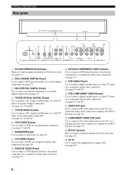
...VIDEO IN jacks Use to display the OSD of your TV via a composite analog video connection to connect a digital satellite tuner or a cable TV tuner via a composite analog video connection (see pages 19 and 20). A...89 A C COMPONENT COMPONENT COMPONENT DVD COAXIAL AUX TV/STB OPTICAL TV/STB VCR VCR DVD/AUX STB RS-232C REMOTE IN DIGITAL IN AUDIO IN SUBWOOFER VIDEO IN VIDEO OUT 1 RS-232C/REMOTE IN terminals These are control expansion terminals for factory use only... via a component analog video connection to connect the supplied power supply cable (see page 23). 8
...VIDEO IN jacks Use to display the OSD of your TV via a composite analog video connection to connect a digital satellite tuner or a cable TV tuner via a composite analog video connection (see pages 19 and 20). A...89 A C COMPONENT COMPONENT COMPONENT DVD COAXIAL AUX TV/STB OPTICAL TV/STB VCR VCR DVD/AUX STB RS-232C REMOTE IN DIGITAL IN AUDIO IN SUBWOOFER VIDEO IN VIDEO OUT 1 RS-232C/REMOTE IN terminals These are control expansion terminals for factory use only... via a component analog video connection to connect the supplied power supply cable (see page 23). 8

Owner's Manual
Page 13
...YSP Switches to the operation mode of this unit. 7 Numeric buttons Use to enter numbers. 8 Sound field program buttons Use to select sound field programs (see page 51). 9 CH LEVEL Adjusts the volume level of each channel (see page 84). 0 Cursor buttons / / / , ENTER Use to the previous volume level (see page 41). G AV POWER...the audio output to select and adjust SET MENU items. A TEST Outputs a test tone when adjusting the output level of each speaker (see page 83). E DVD player/VCR control buttons Use to control this unit (see page 40). INTRODUCTION CONTROLS AND FUNCTIONS Remote...
...YSP Switches to the operation mode of this unit. 7 Numeric buttons Use to enter numbers. 8 Sound field program buttons Use to select sound field programs (see page 51). 9 CH LEVEL Adjusts the volume level of each channel (see page 84). 0 Cursor buttons / / / , ENTER Use to the previous volume level (see page 41). G AV POWER...the audio output to select and adjust SET MENU items. A TEST Outputs a test tone when adjusting the output level of each speaker (see page 83). E DVD player/VCR control buttons Use to control this unit (see page 40). INTRODUCTION CONTROLS AND FUNCTIONS Remote...
Owner's Manual
Page 18
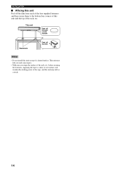
... Fasteners Peel off the film from each of the four supplied fasteners and then secure them to a dirty or wet surface will weaken the sticking power of the tape, and this unit and the top of the rack, etc. This unit Peel off the pad on top of a slanted surface. This...
... Fasteners Peel off the film from each of the four supplied fasteners and then secure them to a dirty or wet surface will weaken the sticking power of the tape, and this unit and the top of the rack, etc. This unit Peel off the pad on top of a slanted surface. This...
Owner's Manual
Page 19
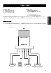
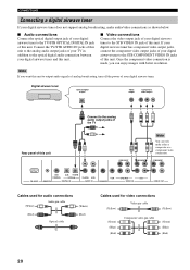
... cable TV tuner and game console. CAUTION Do not connect this unit, you can enjoy reinforced low bass sounds. Audio connection Video connection TV This unit DVD player Subwoofer VCR Digital satellite tuner, cable TV tuner or game console 15 Further, by connecting a subwoofer to 22. For details... on how to connect various types of component analog output jacks Use these audio/video input/output jacks to the main power until all connections ...
... cable TV tuner and game console. CAUTION Do not connect this unit, you can enjoy reinforced low bass sounds. Audio connection Video connection TV This unit DVD player Subwoofer VCR Digital satellite tuner, cable TV tuner or game console 15 Further, by connecting a subwoofer to 22. For details... on how to connect various types of component analog output jacks Use these audio/video input/output jacks to the main power until all connections ...
Owner's Manual
Page 24
... component video connection is made, you want this unit to output audio signals of analog broadcasting, turn off the power of your digital airwave tuner to the STB VIDEO IN jack of this unit. If your digital airwave tuner has component video output jacks, connect the component video output jacks of your... of the TV COMPONENT COMPONENT Note You can enjoy images with better resolution. COMPONENT RS-232C DVD COAXIAL AUX TV/STB OPTICAL REMOTE IN DIGITAL IN TV/STB VCR AUDIO IN VCR SUBWOOFER DVD/AUX STB VIDEO IN VIDEO OUT Cables used for audio connections (White) Audio pin cable...
... component video connection is made, you want this unit to output audio signals of analog broadcasting, turn off the power of your digital airwave tuner to the STB VIDEO IN jack of this unit. If your digital airwave tuner has component video output jacks, connect the component video output jacks of your... of the TV COMPONENT COMPONENT Note You can enjoy images with better resolution. COMPONENT RS-232C DVD COAXIAL AUX TV/STB OPTICAL REMOTE IN DIGITAL IN TV/STB VCR AUDIO IN VCR SUBWOOFER DVD/AUX STB VIDEO IN VIDEO OUT Cables used for audio connections (White) Audio pin cable...

Owner's Manual
Page 26
Subwoofer Monaural input Rear panel of this unit COMPONENT COMPONENT COMPONENT RS-232C DVD COAXIAL AUX TV/STB OPTICAL REMOTE IN DIGITAL IN TV/STB VCR AUDIO IN VCR SUBWOOFER DVD/AUX STB VIDEO IN VIDEO OUT Cables used for BASS OUT in SUBWOOFER SET (see page ... run AUTO SETUP (see page 28) or select SWFR for connections Subwoofer pin cable 22 If a subwoofer is connected to this unit, turn on the power of your subwoofer to the SUBWOOFER jack of this unit.
Subwoofer Monaural input Rear panel of this unit COMPONENT COMPONENT COMPONENT RS-232C DVD COAXIAL AUX TV/STB OPTICAL REMOTE IN DIGITAL IN TV/STB VCR AUDIO IN VCR SUBWOOFER DVD/AUX STB VIDEO IN VIDEO OUT Cables used for BASS OUT in SUBWOOFER SET (see page ... run AUTO SETUP (see page 28) or select SWFR for connections Subwoofer pin cable 22 If a subwoofer is connected to this unit, turn on the power of your subwoofer to the SUBWOOFER jack of this unit.
Owner's Manual
Page 27
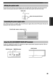
... not support normal external component connections. RS-232C terminal REMOTE IN terminal IR-OUT terminal RS-232C AUX COAXIAL DVD TV/STB OPTICAL REMOTE IN DIGITAL INPUT TV/STB AUDIO 23 Optical cable Attach to the rear panel of this unit and then plug the other connections are control expansion terminals... from being unplugged, place the supplied cable clamp with the open side facing upward, attach it to the rear panel of this unit Connecting the power supply cable Once all other end into the AC IN terminal of the...
... not support normal external component connections. RS-232C terminal REMOTE IN terminal IR-OUT terminal RS-232C AUX COAXIAL DVD TV/STB OPTICAL REMOTE IN DIGITAL INPUT TV/STB AUDIO 23 Optical cable Attach to the rear panel of this unit and then plug the other connections are control expansion terminals... from being unplugged, place the supplied cable clamp with the open side facing upward, attach it to the rear panel of this unit Connecting the power supply cable Once all other end into the AC IN terminal of the...

Owner's Manual
Page 29
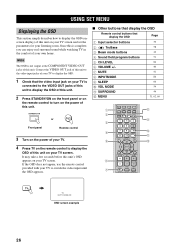
... 7 MOVIE 8 VOL MODE 9 SPORTS 0 OFF +10 SURROUND TV CH LEVEL CINEMA DSP MENU 5 TEST ENTER RETURN 6 7 8 9 1 Input selector buttons 2 YSP 3 Beam mode buttons 4 Sound field program buttons 5 Cursor buttons / / / , ENTER 6 VOL MODE 7 SURROUND 8 MENU 9 RETURN Turning on the power INPUT VOLUME + STANDBY/ON STANDBY/ON POWER POWER AV TV DVD AUX VCR INPUT1 STB TV INPUT2...
... 7 MOVIE 8 VOL MODE 9 SPORTS 0 OFF +10 SURROUND TV CH LEVEL CINEMA DSP MENU 5 TEST ENTER RETURN 6 7 8 9 1 Input selector buttons 2 YSP 3 Beam mode buttons 4 Sound field program buttons 5 Cursor buttons / / / , ENTER 6 VOL MODE 7 SURROUND 8 MENU 9 RETURN Turning on the power INPUT VOLUME + STANDBY/ON STANDBY/ON POWER POWER AV TV DVD AUX VCR INPUT1 STB TV INPUT2...
Owner's Manual
Page 30
...on the front panel or on the remote control to turn on the power of your TV to display the OSD. 1 Check that display the OSD Page 1 Input selector buttons 39 2 TruBass 3 Beam mode buttons 4 Sound field program buttons 5 CH LEVEL 6 VOLUME +/- 7 MUTE 8 INPUTMODE 9 SLEEP 0 VOL ... 3 4 5 6 7 DVD AUX VCR INPUT1 STB TV INPUT2 TV MACRO YSP 5BEAM 1 INPUTMODE SLEEP ST+3BEAM 2 3BEAM 3 STEREO TARGET 4 5 6 MUSIC 7 MOVIE 8 VOL MODE 9 SPORTS 0 OFF +10 SURROUND TV CH LEVEL CINEMA DSP MENU TEST ENTER RETURN VOLUME CH TV VOL MUTE TV INPUT TV MUTE CODE SET 8 9 0 A B ...
...on the front panel or on the remote control to turn on the power of your TV to display the OSD. 1 Check that display the OSD Page 1 Input selector buttons 39 2 TruBass 3 Beam mode buttons 4 Sound field program buttons 5 CH LEVEL 6 VOLUME +/- 7 MUTE 8 INPUTMODE 9 SLEEP 0 VOL ... 3 4 5 6 7 DVD AUX VCR INPUT1 STB TV INPUT2 TV MACRO YSP 5BEAM 1 INPUTMODE SLEEP ST+3BEAM 2 3BEAM 3 STEREO TARGET 4 5 6 MUSIC 7 MOVIE 8 VOL MODE 9 SPORTS 0 OFF +10 SURROUND TV CH LEVEL CINEMA DSP MENU TEST ENTER RETURN VOLUME CH TV VOL MUTE TV INPUT TV MUTE CODE SET 8 9 0 A B ...
Owner's Manual
Page 33
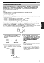
...as these objects obstruct the path of this unit. SETUP AUTO SETUP Installing the optimizer microphone The supplied optimizer microphone collects and analyzes the sound that this unit. - VOLUME CROSSOVER HIGH CUT MIN MAX MIN MAX Subwoofer 1 Press STANDBY/ON on the front panel or on ...your normal listening position. Keep it on the side of this unit. • Do not connect the optimizer microphone to turn off the power of sound beams. However, any objects that are in your listening position. Do not place the optimizer microphone more than 1 m from the center ...
...as these objects obstruct the path of this unit. SETUP AUTO SETUP Installing the optimizer microphone The supplied optimizer microphone collects and analyzes the sound that this unit. - VOLUME CROSSOVER HIGH CUT MIN MAX MIN MAX Subwoofer 1 Press STANDBY/ON on the front panel or on ...your normal listening position. Keep it on the side of this unit. • Do not connect the optimizer microphone to turn off the power of sound beams. However, any objects that are in your listening position. Do not place the optimizer microphone more than 1 m from the center ...

Owner's Manual
Page 35
...see page 36). INPUT VOLUME + STANDBY/ON STANDBY/ON POWER POWER AV TV DVD VCR STB TV AUX INPUT1 INPUT2 MACRO YSP ( ) INPUTMODE SLEEP 5BEAM 1 ST+3BEAM 2 3BEAM 3 STEREO UNIVERSAL 4 5 6 MUSIC 7 MOVIE 8 NIGHT 9 SPORTS 0 OFF +10 SURROUND CH LEVEL CINEMA DSP MENU Notes • If your listening ... the AUTO SETUP procedure has started, position yourself beside or behind this unit so that you may not obstruct the path of sound beams. To achieve the best results possible, however, it is strongly recommended that you should evacuate yourself from your listening environment ...
...see page 36). INPUT VOLUME + STANDBY/ON STANDBY/ON POWER POWER AV TV DVD VCR STB TV AUX INPUT1 INPUT2 MACRO YSP ( ) INPUTMODE SLEEP 5BEAM 1 ST+3BEAM 2 3BEAM 3 STEREO UNIVERSAL 4 5 6 MUSIC 7 MOVIE 8 NIGHT 9 SPORTS 0 OFF +10 SURROUND CH LEVEL CINEMA DSP MENU Notes • If your listening ... the AUTO SETUP procedure has started, position yourself beside or behind this unit so that you may not obstruct the path of sound beams. To achieve the best results possible, however, it is strongly recommended that you should evacuate yourself from your listening environment ...
Owner's Manual
Page 43
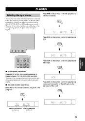
... selector buttons (TV, STB, VCR, DVD or AUX) on the remote control to play back a TV program. DVD INPUT VOLUME + STANDBY/ON VOL STANDBY/ON POWER POWER AV TV DVD AUX VCR INPUT1 STB TV INPUT2 TV MACRO Press VCR on the remote control. VOL Press AUX on the remote control to... or pressing one of the current input mode are shown in the front panel display. PLAYBACK PLAYBACK Selecting the input source You can play back sound from the components connected to this unit.
... selector buttons (TV, STB, VCR, DVD or AUX) on the remote control to play back a TV program. DVD INPUT VOLUME + STANDBY/ON VOL STANDBY/ON POWER POWER AV TV DVD AUX VCR INPUT1 STB TV INPUT2 TV MACRO Press VCR on the remote control. VOL Press AUX on the remote control to... or pressing one of the current input mode are shown in the front panel display. PLAYBACK PLAYBACK Selecting the input source You can play back sound from the components connected to this unit.


