Owner's Manual
Page 4
...or splashing. CAUTION Danger of space above (or below . YAMAHA will form when the surrounding temperature changes suddenly. Note that the...is faulty. 16 Before moving this unit, press STANDBY/ON to set this unit in standby mode, and disconnect the AC power plug from...unit away from other electrical appliances, motors, or transformers to avoid humming sounds. 4 Do not expose this unit to sudden temperature changes from use... that neither core is called the standby mode. This Class B digital apparatus complies with the same or equivalent type. CAUTION: READ THIS...
...or splashing. CAUTION Danger of space above (or below . YAMAHA will form when the surrounding temperature changes suddenly. Note that the...is faulty. 16 Before moving this unit, press STANDBY/ON to set this unit in standby mode, and disconnect the AC power plug from...unit away from other electrical appliances, motors, or transformers to avoid humming sounds. 4 Do not expose this unit to sudden temperature changes from use... that neither core is called the standby mode. This Class B digital apparatus complies with the same or equivalent type. CAUTION: READ THIS...

Owner's Manual
Page 5
...11 CONNECTIONS 15 Connecting a TV 16 Connecting a DVD player/recorder 17 Connecting a VCR 18 Connecting a digital satellite tuner or a cable TV tuner 19 Connecting a digital airwave tuner 20 Connecting other external components 21 Connecting a subwoofer 22 Affixing the optical cable 23 Connecting the... 68 Using MANUAL SETUP 69 BEAM MENU 70 SOUND MENU 74 INPUT MENU 77 DISPLAY MENU 79 ADJUSTING SYSTEM PARAMETERS ...........80 Setting the maximum volume level 80 Protecting the current settings 81 Initializing the current settings 82 Adjusting the audio balance 83 SELECTING THE ...
...11 CONNECTIONS 15 Connecting a TV 16 Connecting a DVD player/recorder 17 Connecting a VCR 18 Connecting a digital satellite tuner or a cable TV tuner 19 Connecting a digital airwave tuner 20 Connecting other external components 21 Connecting a subwoofer 22 Affixing the optical cable 23 Connecting the... 68 Using MANUAL SETUP 69 BEAM MENU 70 SOUND MENU 74 INPUT MENU 77 DISPLAY MENU 79 ADJUSTING SYSTEM PARAMETERS ...........80 Setting the maximum volume level 80 Protecting the current settings 81 Initializing the current settings 82 Adjusting the audio balance 83 SELECTING THE ...
Owner's Manual
Page 6
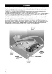
... the parameters of this unit to -life 5.1 channel surround sound that makes you feel as your listening room before reaching the actual listening position. YAMAHA YSP-1000 Digital Sound Projector challenges this preconception that complicated speaker setup and troublesome wiring go hand-in-hand with a unit...off the walls of multi-channel surround sound. With the addition of center (C) sound beams, this simple, yet stylish Digital Sound Projector. OVERVIEW OVERVIEW It is generally accepted that in order to set up, but which are actual speakers around the room. This slimline unit...
... the parameters of this unit to -life 5.1 channel surround sound that makes you feel as your listening room before reaching the actual listening position. YAMAHA YSP-1000 Digital Sound Projector challenges this preconception that complicated speaker setup and troublesome wiring go hand-in-hand with a unit...off the walls of multi-channel surround sound. With the addition of center (C) sound beams, this simple, yet stylish Digital Sound Projector. OVERVIEW OVERVIEW It is generally accepted that in order to set up, but which are actual speakers around the room. This slimline unit...
Owner's Manual
Page 7
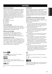
...9670; Target mode Cinema DSP Digital This unit employs the Cinema DSP Digital technology developed by YAMAHA Electronics Corp. INTRODUCTION FEATURES FEATURES Digital Sound Projector This unit employs the digital sound projector technology that allows one slim...modes so that you can avoid troublesome listening-based speaker setup and achieve highly accurate sound beam adjustments that best match your listening environment.... effect. ◆ DTS (Digital Theater Systems) This is an audio signal format used to display the system information or adjust settings for maximum 6 channel playback,...
...9670; Target mode Cinema DSP Digital This unit employs the Cinema DSP Digital technology developed by YAMAHA Electronics Corp. INTRODUCTION FEATURES FEATURES Digital Sound Projector This unit employs the digital sound projector technology that allows one slim...modes so that you can avoid troublesome listening-based speaker setup and achieve highly accurate sound beam adjustments that best match your listening environment.... effect. ◆ DTS (Digital Theater Systems) This is an audio signal format used to display the system information or adjust settings for maximum 6 channel playback,...
Owner's Manual
Page 8
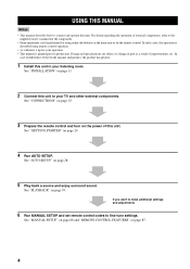
For details regarding the operation of external components, refer to fine-tune settings. See "CONNECTIONS" on page 15. 3 Prepare the remote control and turn on the power of improvements, etc. See "AUTO SETUP" on page 39. In case ... unit in part as a result of this unit. See "PLAYBACK" on page 28. 5 Play back a source and enjoy surround sound. If you want to make additional settings and adjustments 6 Run MANUAL SETUP and set remote control codes to the supplied owner's manual for the component. • Some operations can be performed by using...
For details regarding the operation of external components, refer to fine-tune settings. See "CONNECTIONS" on page 15. 3 Prepare the remote control and turn on the power of improvements, etc. See "AUTO SETUP" on page 39. In case ... unit in part as a result of this unit. See "PLAYBACK" on page 28. 5 Play back a source and enjoy surround sound. If you want to make additional settings and adjustments 6 Run MANUAL SETUP and set remote control codes to the supplied owner's manual for the component. • Some operations can be performed by using...

Owner's Manual
Page 9
... STB TV INPUT2 TV MACRO YSP 5BEAM 1 INPUTMODE SLEEP ST+3BEAM 2 3BEAM 3 STEREO TARGET 4 5 6 MUSIC 7 MOVIE 8 VOL MODE 9 SPORTS 0 OFF +10 SURROUND CH LEVEL CINEMA DSP MENU TEST ENTER RETURN VOLUME CH TV VOL Video pin cable (×1) Digital audio pin cable (×1)... (Yellow) Optimizer microphone (×1) (Orange) Audio pin cable (×1) MUTE TV INPUT TV MUTE CODE SET Cable clamp (×1) (White/Red)...
... STB TV INPUT2 TV MACRO YSP 5BEAM 1 INPUTMODE SLEEP ST+3BEAM 2 3BEAM 3 STEREO TARGET 4 5 6 MUSIC 7 MOVIE 8 VOL MODE 9 SPORTS 0 OFF +10 SURROUND CH LEVEL CINEMA DSP MENU TEST ENTER RETURN VOLUME CH TV VOL Video pin cable (×1) Digital audio pin cable (×1)... (Yellow) Optimizer microphone (×1) (Orange) Audio pin cable (×1) MUTE TV INPUT TV MUTE CODE SET Cable clamp (×1) (White/Red)...

Owner's Manual
Page 10
... all audio channels (see page 40). 6 STANDBY/ON Turns on the power of this unit, you turn on the power of this unit or sets it can reproduce sound. • In the standby mode, this unit consumes a small amount of this unit. 3 Remote control sensor Receives infrared signals from the remote control...
... all audio channels (see page 40). 6 STANDBY/ON Turns on the power of this unit, you turn on the power of this unit or sets it can reproduce sound. • In the standby mode, this unit consumes a small amount of this unit. 3 Remote control sensor Receives infrared signals from the remote control...

Owner's Manual
Page 13
... 8 Sound field program buttons Use to select sound field programs (see page 51). 9 CH LEVEL Adjusts the volume level of each channel (see page 84). 0 Cursor buttons / / / , ENTER Use to select and adjust SET MENU ...the control area (see page 39). 5 TruBass Use to effectively reproduce the bass sound (see page 58). 6 YSP Switches to the operation mode of this unit (see page 40). Press again to...FUNCTIONS Remote control This section describes the function of each speaker (see page 83). Aim this window at the component you set the appropriate remote control codes. y You can also control...
... 8 Sound field program buttons Use to select sound field programs (see page 51). 9 CH LEVEL Adjusts the volume level of each channel (see page 84). 0 Cursor buttons / / / , ENTER Use to select and adjust SET MENU ...the control area (see page 39). 5 TruBass Use to effectively reproduce the bass sound (see page 58). 6 YSP Switches to the operation mode of this unit (see page 40). Press again to...FUNCTIONS Remote control This section describes the function of each speaker (see page 83). Aim this window at the component you set the appropriate remote control codes. y You can also control...
Owner's Manual
Page 14
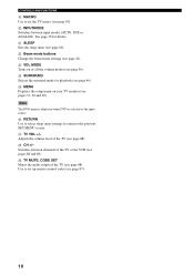
...). M VOL MODE Turns on your TV monitor (see pages 31, 62 and 69). K SLEEP Sets the sleep timer (see page 88). O MENU Displays the setup menu on or off the volume modes (see page 56). Use to set the TV macro (see page 90). See page 39 for playback (see page 46...). R CH +/- CONTROLS AND FUNCTIONS I MACRO Use to set up remote control codes (see page 87). 10 J INPUTMODE Switches between channels of the TV...
...). M VOL MODE Turns on your TV monitor (see pages 31, 62 and 69). K SLEEP Sets the sleep timer (see page 88). O MENU Displays the setup menu on or off the volume modes (see page 56). Use to set the TV macro (see page 90). See page 39 for playback (see page 46...). R CH +/- CONTROLS AND FUNCTIONS I MACRO Use to set up remote control codes (see page 87). 10 J INPUTMODE Switches between channels of the TV...
Owner's Manual
Page 19
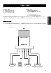
... Subwoofer VCR Digital satellite tuner,... digital input jacks • 1 coaxial digital input jack • 2 sets of analog input jacks For video input • 3 composite analog input jacks • 2 sets ...of component analog input jacks For video output • 1 composite analog output jack • 1 set... of external components to this unit, see pages 16 to this unit or other components to connect external components such as your TV, DVD player, VCR, digital...
... Subwoofer VCR Digital satellite tuner,... digital input jacks • 1 coaxial digital input jack • 2 sets of analog input jacks For video input • 3 composite analog input jacks • 2 sets ...of component analog input jacks For video output • 1 composite analog output jack • 1 set... of external components to this unit, see pages 16 to this unit or other components to connect external components such as your TV, DVD player, VCR, digital...
Owner's Manual
Page 20
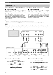
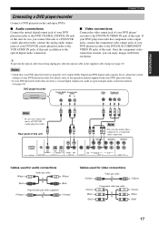
... jack of this unit in addition to the analog unit in addition to the analog audio and optical digital audio output jacks at the same time as shown in SET MENU. ■ Audio connections ■ Video connections Connect the analog audio output jacks of your TV to the Connect the video input... jacks of your TV has an OUT jack of this unit. Once the digital audio connection is the component video connection...
... jack of this unit in addition to the analog unit in addition to the analog audio and optical digital audio output jacks at the same time as shown in SET MENU. ■ Audio connections ■ Video connections Connect the analog audio output jacks of your TV to the Connect the video input... jacks of your TV has an OUT jack of this unit. Once the digital audio connection is the component video connection...
Owner's Manual
Page 21
... audio output output RL Video input Component video input Note * In case you can only make an optical digital audio connection instead (see page 23). connection is properly set to output Dolby Digital and DTS digital audio signals. PREPARATION CONNECTIONS Connecting a DVD player/recorder Connect a DVD player/recorder and enjoy DVDs. ■ Audio connections...
... audio output output RL Video input Component video input Note * In case you can only make an optical digital audio connection instead (see page 23). connection is properly set to output Dolby Digital and DTS digital audio signals. PREPARATION CONNECTIONS Connecting a DVD player/recorder Connect a DVD player/recorder and enjoy DVDs. ■ Audio connections...

Owner's Manual
Page 25
CONNECTIONS Connecting other external components To connect other external components, connect the optical digital output jack of an external component to connect a DVD player/recorder via an optical digital connection, adjust settings for connections Optical cable 21 Optical digital output PREPARATION COMPONENT Rear panel of this unit COMPONENT COMPONENT DVD COAXIAL AUX TV/STB OPTICAL...
CONNECTIONS Connecting other external components To connect other external components, connect the optical digital output jack of an external component to connect a DVD player/recorder via an optical digital connection, adjust settings for connections Optical cable 21 Optical digital output PREPARATION COMPONENT Rear panel of this unit COMPONENT COMPONENT DVD COAXIAL AUX TV/STB OPTICAL...

Owner's Manual
Page 26
... unit COMPONENT COMPONENT COMPONENT RS-232C DVD COAXIAL AUX TV/STB OPTICAL REMOTE IN DIGITAL IN TV/STB VCR AUDIO IN VCR SUBWOOFER DVD/AUX STB VIDEO IN VIDEO OUT Cables used for BASS OUT in SUBWOOFER SET (see page 28) or select SWFR for connections Subwoofer pin cable 22 If a subwoofer...
... unit COMPONENT COMPONENT COMPONENT RS-232C DVD COAXIAL AUX TV/STB OPTICAL REMOTE IN DIGITAL IN TV/STB VCR AUDIO IN VCR SUBWOOFER DVD/AUX STB VIDEO IN VIDEO OUT Cables used for BASS OUT in SUBWOOFER SET (see page 28) or select SWFR for connections Subwoofer pin cable 22 If a subwoofer...

Owner's Manual
Page 29
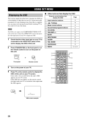
...INPUTMODE SLEEP ST+3BEAM 2 TARGET 5 3BEAM 3 TV 6 MUSIC 7 MOVIE 8 VOL MODE 9 SPORTS 0 OFF +10 SURROUND TV CH LEVEL CINEMA DSP MENU 5 TEST ENTER RETURN 6 7 8 9 1 Input selector buttons 2 YSP 3 Beam mode buttons 4 Sound field program buttons 5 Cursor buttons / / / , ENTER 6 VOL MODE 7 SURROUND 8 MENU 9 RETURN Turning on the power...to turn on the remote control again to the operation mode of this unit. y You can control other components by setting the appropriate remote control codes (see "Controlling other control buttons on the front panel or on the remote control are ...
...INPUTMODE SLEEP ST+3BEAM 2 TARGET 5 3BEAM 3 TV 6 MUSIC 7 MOVIE 8 VOL MODE 9 SPORTS 0 OFF +10 SURROUND TV CH LEVEL CINEMA DSP MENU 5 TEST ENTER RETURN 6 7 8 9 1 Input selector buttons 2 YSP 3 Beam mode buttons 4 Sound field program buttons 5 Cursor buttons / / / , ENTER 6 VOL MODE 7 SURROUND 8 MENU 9 RETURN Turning on the power...to turn on the remote control again to the operation mode of this unit. y You can control other components by setting the appropriate remote control codes (see "Controlling other control buttons on the front panel or on the remote control are ...
Owner's Manual
Page 30
... 5 6 7 DVD AUX VCR INPUT1 STB TV INPUT2 TV MACRO YSP 5BEAM 1 INPUTMODE SLEEP ST+3BEAM 2 3BEAM 3 STEREO TARGET 4 5 6 MUSIC 7 MOVIE 8 VOL MODE 9 SPORTS 0 OFF +10 SURROUND TV CH LEVEL CINEMA DSP MENU TEST ENTER RETURN VOLUME CH TV VOL MUTE TV INPUT TV MUTE CODE SET 8 9 0 A B TV TV AUTO:ANALOG OSD screen example 26...remote control to display the OSD of this unit on your own home. Note The OSD is complete, you can enjoy real surround sound while watching TV in the comfort of your TV screen. Once this is not output at the COMPONENT VIDEO OUT jacks of this ...
... 5 6 7 DVD AUX VCR INPUT1 STB TV INPUT2 TV MACRO YSP 5BEAM 1 INPUTMODE SLEEP ST+3BEAM 2 3BEAM 3 STEREO TARGET 4 5 6 MUSIC 7 MOVIE 8 VOL MODE 9 SPORTS 0 OFF +10 SURROUND TV CH LEVEL CINEMA DSP MENU TEST ENTER RETURN VOLUME CH TV VOL MUTE TV INPUT TV MUTE CODE SET 8 9 0 A B TV TV AUTO:ANALOG OSD screen example 26...remote control to display the OSD of this unit on your own home. Note The OSD is complete, you can enjoy real surround sound while watching TV in the comfort of your TV screen. Once this is not output at the COMPONENT VIDEO OUT jacks of this ...
Owner's Manual
Page 31
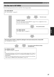
... persists Play back audio signals or adjust the settings for a remedy. If you cannot clearly hear a sound beam from a specific speaker channel, adjust settings for SETTING PARAMETERS (see page 70) or for BEAM ADJUSTMENT (see page 73). 27 USING SET MENU If an error occurs Look for the beam...• If there are acoustically absorbent objects such as curtains in the path of the sound beams, adjust settings for a complete list of the setup procedure. SETUP The flow chart of SET MENU The following diagram illustrates the overall flow of error messages and possible remedies. Run BASIC...
... persists Play back audio signals or adjust the settings for a remedy. If you cannot clearly hear a sound beam from a specific speaker channel, adjust settings for SETTING PARAMETERS (see page 70) or for BEAM ADJUSTMENT (see page 73). 27 USING SET MENU If an error occurs Look for the beam...• If there are acoustically absorbent objects such as curtains in the path of the sound beams, adjust settings for a complete list of the setup procedure. SETUP The flow chart of SET MENU The following diagram illustrates the overall flow of error messages and possible remedies. Run BASIC...
Owner's Manual
Page 32
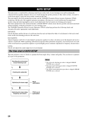
... the phase and the distance of each channel. The YAMAHA Parametric Room Acoustic Optimizer (YPAO) technology performs the following checks and automatically makes appropriate sound adjustments. YPAO equalizing calibration incorporates three parameters (frequency, level...sound optimization 28 Checking the environment of BASIC SETUP, which creates the best possible surround sound field without manually setting the parameters for each channel's parametric equalizer to avoid troublesome listening-based speaker setup and achieving highly accurate sound adjustments that each sound...
... the phase and the distance of each channel. The YAMAHA Parametric Room Acoustic Optimizer (YPAO) technology performs the following checks and automatically makes appropriate sound adjustments. YPAO equalizing calibration incorporates three parameters (frequency, level...sound optimization 28 Checking the environment of BASIC SETUP, which creates the best possible surround sound field without manually setting the parameters for each channel's parametric equalizer to avoid troublesome listening-based speaker setup and achieving highly accurate sound adjustments that each sound...
Owner's Manual
Page 33
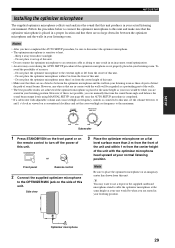
...this unit. Side view Note Be sure to place the optimizer microphone on a conventional clockface and set the crossover/high cut frequency to the extreme right or left from the front of sound beams. However, any objects that are in contact with the optimizer microphone head upward at the ... angle and balance the sound beam output levels using MANUAL SETUP (see page 68) once the AUTO SETUP procedure is completed. • If a subwoofer with adjustable volume and crossover/high cut frequency controls is connected to this unit, set the volume between the optimizer microphone and the walls ...
...this unit. Side view Note Be sure to place the optimizer microphone on a conventional clockface and set the crossover/high cut frequency to the extreme right or left from the front of sound beams. However, any objects that are in contact with the optimizer microphone head upward at the ... angle and balance the sound beam output levels using MANUAL SETUP (see page 68) once the AUTO SETUP procedure is completed. • If a subwoofer with adjustable volume and crossover/high cut frequency controls is connected to this unit, set the volume between the optimizer microphone and the walls ...

Owner's Manual
Page 35
...in your listening environment (see page 36). A set of settings optimized according to specific conditions of your listening environment can save the settings optimized by the AUTO SETUP procedure (see page... on the screen, see "Error messages for AUTO SETUP" on the power of sound beams. To achieve the best results possible, however, it is strongly recommended that you... VCR STB TV AUX INPUT1 INPUT2 MACRO YSP ( ) INPUTMODE SLEEP 5BEAM 1 ST+3BEAM 2 3BEAM 3 STEREO UNIVERSAL 4 5 6 MUSIC 7 MOVIE 8 NIGHT 9 SPORTS 0 OFF +10 SURROUND CH LEVEL CINEMA DSP MENU Notes •...
...in your listening environment (see page 36). A set of settings optimized according to specific conditions of your listening environment can save the settings optimized by the AUTO SETUP procedure (see page... on the screen, see "Error messages for AUTO SETUP" on the power of sound beams. To achieve the best results possible, however, it is strongly recommended that you... VCR STB TV AUX INPUT1 INPUT2 MACRO YSP ( ) INPUTMODE SLEEP 5BEAM 1 ST+3BEAM 2 3BEAM 3 STEREO UNIVERSAL 4 5 6 MUSIC 7 MOVIE 8 NIGHT 9 SPORTS 0 OFF +10 SURROUND CH LEVEL CINEMA DSP MENU Notes •...