
Owner's Manual
Page 5
... a TV 16 Connecting a DVD player/recorder 17 Connecting a VCR 18 Connecting a digital satellite tuner or a cable TV tuner 19 Connecting a digital airwave tuner 20 Connecting other external components 21 Connecting a subwoofer 22 Affixing the optical cable 23 Connecting the power supply cable 23 About the RS-...timer 60 Canceling the sleep timer 61 ADVANCED OPERATION BASIC SETUP 62 MANUAL SETUP 68 Using MANUAL SETUP 69 BEAM MENU 70 SOUND MENU 74 INPUT MENU 77 DISPLAY MENU 79 ADJUSTING SYSTEM PARAMETERS ...........80 Setting the maximum volume level 80 Protecting the current ...
... a TV 16 Connecting a DVD player/recorder 17 Connecting a VCR 18 Connecting a digital satellite tuner or a cable TV tuner 19 Connecting a digital airwave tuner 20 Connecting other external components 21 Connecting a subwoofer 22 Affixing the optical cable 23 Connecting the power supply cable 23 About the RS-...timer 60 Canceling the sleep timer 61 ADVANCED OPERATION BASIC SETUP 62 MANUAL SETUP 68 Using MANUAL SETUP 69 BEAM MENU 70 SOUND MENU 74 INPUT MENU 77 DISPLAY MENU 79 ADJUSTING SYSTEM PARAMETERS ...........80 Setting the maximum volume level 80 Protecting the current ...
Owner's Manual
Page 6
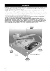
... (SL) speaker positions, which is also capable of reproducing the kind of powerful surround sound you the same kind of surround sound experience as if there are reflected off the walls of this Digital Sound Projector creates true-to-life 5.1 channel surround sound that makes you feel as your local movie theater. YAMAHA YSP-1000 Digital Sound Projector challenges this simple, yet stylish Digital Sound Projector.
... (SL) speaker positions, which is also capable of reproducing the kind of powerful surround sound you the same kind of surround sound experience as if there are reflected off the walls of this Digital Sound Projector creates true-to-life 5.1 channel surround sound that makes you feel as your local movie theater. YAMAHA YSP-1000 Digital Sound Projector challenges this simple, yet stylish Digital Sound Projector.
Owner's Manual
Page 7
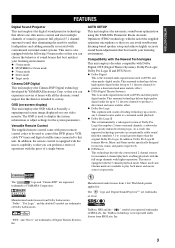
...cable TV tuner and digital satellite tuner connected to this improved technology provides an exceptionally stable sound field that employs 2 stereo surround channels, a subwoofer and a greatly enhanced...Pro Logic. The " " logo and "Cinema DSP" are trademarks of YAMAHA Corporation. The ' ' logo and 'Digital Sound Projector™' are registered trademarks of 1 Ltd. TruBass technology is incorporated under...of operations with all the dramatic sound impact that you can avoid troublesome listening-based speaker setup and achieve highly accurate sound beam adjustments that best match ...
...cable TV tuner and digital satellite tuner connected to this improved technology provides an exceptionally stable sound field that employs 2 stereo surround channels, a subwoofer and a greatly enhanced...Pro Logic. The " " logo and "Cinema DSP" are trademarks of YAMAHA Corporation. The ' ' logo and 'Digital Sound Projector™' are registered trademarks of 1 Ltd. TruBass technology is incorporated under...of operations with all the dramatic sound impact that you can avoid troublesome listening-based speaker setup and achieve highly accurate sound beam adjustments that best match ...
Owner's Manual
Page 12
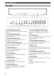
... B D 1 2 34 5 6 7 89 A C COMPONENT COMPONENT COMPONENT DVD COAXIAL AUX TV/STB OPTICAL TV/STB VCR VCR DVD/AUX STB RS-232C REMOTE IN DIGITAL IN AUDIO IN SUBWOOFER VIDEO IN VIDEO OUT 1 RS-232C/REMOTE IN terminals These are control expansion terminals for factory use only (see page 23). 2 DVD COAXIAL...to connect a TV, a digital satellite tuner or a cable TV tuner via an analog audio connection (see page 16, 19 and 20). 6 VCR AUDIO IN jacks Use to connect a VCR via an analog audio connection (see pages 17 and 18). 7 SUBWOOFER jack Use to connect a subwoofer (see page 22). 8...
... B D 1 2 34 5 6 7 89 A C COMPONENT COMPONENT COMPONENT DVD COAXIAL AUX TV/STB OPTICAL TV/STB VCR VCR DVD/AUX STB RS-232C REMOTE IN DIGITAL IN AUDIO IN SUBWOOFER VIDEO IN VIDEO OUT 1 RS-232C/REMOTE IN terminals These are control expansion terminals for factory use only (see page 23). 2 DVD COAXIAL...to connect a TV, a digital satellite tuner or a cable TV tuner via an analog audio connection (see page 16, 19 and 20). 6 VCR AUDIO IN jacks Use to connect a VCR via an analog audio connection (see pages 17 and 18). 7 SUBWOOFER jack Use to connect a subwoofer (see page 22). 8...
Owner's Manual
Page 19
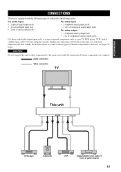
... components such as your TV, DVD player, VCR, digital satellite tuner, cable TV tuner and game console. Audio connection Video connection TV This unit DVD player Subwoofer VCR Digital satellite tuner, cable TV tuner or game console 15 ...digital input jacks • 1 coaxial digital input jack • 2 sets of analog input jacks For video input • 3 composite analog input jacks • 2 sets of component analog input jacks For video output • 1 composite analog output jack • 1 set of external components to this unit, you can enjoy reinforced low bass sounds...
... components such as your TV, DVD player, VCR, digital satellite tuner, cable TV tuner and game console. Audio connection Video connection TV This unit DVD player Subwoofer VCR Digital satellite tuner, cable TV tuner or game console 15 ...digital input jacks • 1 coaxial digital input jack • 2 sets of analog input jacks For video input • 3 composite analog input jacks • 2 sets of component analog input jacks For video output • 1 composite analog output jack • 1 set of external components to this unit, you can enjoy reinforced low bass sounds...
Owner's Manual
Page 20
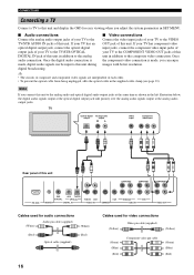
... of this unit COMPONENT COMPONENT COMPONENT DVD COAXIAL AUX TV/STB OPTICAL TV/STB VCR VCR DVD/AUX STB RS-232C REMOTE IN DIGITAL IN AUDIO IN SUBWOOFER VIDEO IN VIDEO OUT Cables used for audio connections (White) Audio pin cable (supplied) (White) (Red) Optical cable (supplied... TV/STB AUDIO IN jacks of this unit in addition to the analog unit in addition to the composite video connection. digital broadcasting. TV Optical digital output Analog audio output RL Video input Component video input Rear panel of this unit. CONNECTIONS Connecting a TV Connect a...
... of this unit COMPONENT COMPONENT COMPONENT DVD COAXIAL AUX TV/STB OPTICAL TV/STB VCR VCR DVD/AUX STB RS-232C REMOTE IN DIGITAL IN AUDIO IN SUBWOOFER VIDEO IN VIDEO OUT Cables used for audio connections (White) Audio pin cable (supplied) (White) (Red) Optical cable (supplied... TV/STB AUDIO IN jacks of this unit in addition to the analog unit in addition to the composite video connection. digital broadcasting. TV Optical digital output Analog audio output RL Video input Component video input Rear panel of this unit. CONNECTIONS Connecting a TV Connect a...
Owner's Manual
Page 21
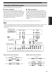
... DVD player/recorder. • If your DVD player/recorder does not have a coaxial digital output jack, make either a composite or a component video connection. Once the component video optical digital audio connection. For details, refer to the operation manual supplied with better resolution. PREPARATION .../STB OPTICAL TV/STB VCR VCR DVD/AUX STB RS-232C REMOTE IN DIGITAL IN AUDIO IN SUBWOOFER VIDEO IN VIDEO OUT Cables used for audio connections (White) Audio pin cable (White) (Red) (Red) Digital audio pin cable (supplied) (Orange) (Orange) Cables used for video...
... DVD player/recorder. • If your DVD player/recorder does not have a coaxial digital output jack, make either a composite or a component video connection. Once the component video optical digital audio connection. For details, refer to the operation manual supplied with better resolution. PREPARATION .../STB OPTICAL TV/STB VCR VCR DVD/AUX STB RS-232C REMOTE IN DIGITAL IN AUDIO IN SUBWOOFER VIDEO IN VIDEO OUT Cables used for audio connections (White) Audio pin cable (White) (Red) (Red) Digital audio pin cable (supplied) (Orange) (Orange) Cables used for video...

Owner's Manual
Page 22
... input jacks of this unit COMPONENT COMPONENT DVD COAXIAL AUX TV/STB OPTICAL TV/STB VCR VCR DVD/AUX STB RS-232C REMOTE IN DIGITAL IN AUDIO IN SUBWOOFER VIDEO IN VIDEO OUT Cables used for audio connections (White) Audio pin cable (White) (Red) (Red) Cables used for video connections (Yellow) Video...
... input jacks of this unit COMPONENT COMPONENT DVD COAXIAL AUX TV/STB OPTICAL TV/STB VCR VCR DVD/AUX STB RS-232C REMOTE IN DIGITAL IN AUDIO IN SUBWOOFER VIDEO IN VIDEO OUT Cables used for audio connections (White) Audio pin cable (White) (Red) (Red) Cables used for video connections (Yellow) Video...

Owner's Manual
Page 23
... output Rear panel of this unit. COMPONENT DVD COAXIAL AUX TV/STB OPTICAL TV/STB VCR VCR DVD/AUX STB RS-232C REMOTE IN DIGITAL IN AUDIO IN SUBWOOFER VIDEO IN VIDEO OUT Cables used for audio connections (White) Audio pin cable (White) (Red) Optical cable (Red) Cables used for video connections...
... output Rear panel of this unit. COMPONENT DVD COAXIAL AUX TV/STB OPTICAL TV/STB VCR VCR DVD/AUX STB RS-232C REMOTE IN DIGITAL IN AUDIO IN SUBWOOFER VIDEO IN VIDEO OUT Cables used for audio connections (White) Audio pin cable (White) (Red) Optical cable (Red) Cables used for video connections...
Owner's Manual
Page 24
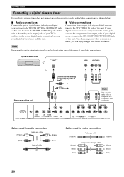
... tuner to the STB COMPONENT VIDEO IN jacks of this unit. COMPONENT RS-232C DVD COAXIAL AUX TV/STB OPTICAL REMOTE IN DIGITAL IN TV/STB VCR AUDIO IN VCR SUBWOOFER DVD/AUX STB VIDEO IN VIDEO OUT Cables used for audio connections (White) Audio pin cable (White) (Red) Optical cable (Red...
... tuner to the STB COMPONENT VIDEO IN jacks of this unit. COMPONENT RS-232C DVD COAXIAL AUX TV/STB OPTICAL REMOTE IN DIGITAL IN TV/STB VCR AUDIO IN VCR SUBWOOFER DVD/AUX STB VIDEO IN VIDEO OUT Cables used for audio connections (White) Audio pin cable (White) (Red) Optical cable (Red...

Owner's Manual
Page 25
...CD player, etc. Use this connection method to connect an external component that supports an optical digital connection or to the AUX OPTICAL DIGITAL IN jack of this unit. Optical digital output PREPARATION COMPONENT Rear panel of this unit COMPONENT COMPONENT DVD COAXIAL AUX TV/STB OPTICAL TV.../STB VCR VCR DVD/AUX STB RS-232C REMOTE IN DIGITAL IN AUDIO IN SUBWOOFER VIDEO IN VIDEO OUT ...
...CD player, etc. Use this connection method to connect an external component that supports an optical digital connection or to the AUX OPTICAL DIGITAL IN jack of this unit. Optical digital output PREPARATION COMPONENT Rear panel of this unit COMPONENT COMPONENT DVD COAXIAL AUX TV/STB OPTICAL TV.../STB VCR VCR DVD/AUX STB RS-232C REMOTE IN DIGITAL IN AUDIO IN SUBWOOFER VIDEO IN VIDEO OUT ...

Owner's Manual
Page 26
... AUTO SETUP (see page 28) or select SWFR for connections Subwoofer pin cable 22 Subwoofer Monaural input Rear panel of this unit COMPONENT COMPONENT COMPONENT RS-232C DVD COAXIAL AUX TV/STB OPTICAL REMOTE IN DIGITAL IN TV/STB VCR AUDIO IN VCR SUBWOOFER DVD/AUX STB VIDEO IN VIDEO OUT Cables used for...
... AUTO SETUP (see page 28) or select SWFR for connections Subwoofer pin cable 22 Subwoofer Monaural input Rear panel of this unit COMPONENT COMPONENT COMPONENT RS-232C DVD COAXIAL AUX TV/STB OPTICAL REMOTE IN DIGITAL IN TV/STB VCR AUDIO IN VCR SUBWOOFER DVD/AUX STB VIDEO IN VIDEO OUT Cables used for...
Owner's Manual
Page 32
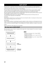
The YAMAHA Parametric Room Acoustic Optimizer (YPAO) technology performs the following checks and automatically makes appropriate sound adjustments. YPAO equalizing calibration incorporates three parameters (frequency, level and Q factor) for your listening room *1 Checking the subwoofer Notes *1 The subwoofer checking procedure is...delay, frequency and volume Beam optimization YPAO sound optimization 28 Just as you would arrange the speaker position of other audio systems, you to reduce coloration across the channels and create a cohesive sound field. DISTANCE: Checks the phase and the...
The YAMAHA Parametric Room Acoustic Optimizer (YPAO) technology performs the following checks and automatically makes appropriate sound adjustments. YPAO equalizing calibration incorporates three parameters (frequency, level and Q factor) for your listening room *1 Checking the subwoofer Notes *1 The subwoofer checking procedure is...delay, frequency and volume Beam optimization YPAO sound optimization 28 Just as you would arrange the speaker position of other audio systems, you to reduce coloration across the channels and create a cohesive sound field. DISTANCE: Checks the phase and the...
Owner's Manual
Page 33
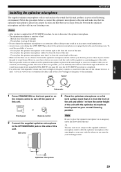
...However, if this is not possible, you can manually fine-tune the sound beam angle and balance the sound beam output levels using MANUAL SETUP (see page 68) once the AUTO SETUP procedure is completed. • If a subwoofer with the walls will be regarded as your ears would be when you ...are seated in your listening room. VOLUME CROSSOVER HIGH CUT MIN MAX MIN MAX Subwoofer 1 Press...
...However, if this is not possible, you can manually fine-tune the sound beam angle and balance the sound beam output levels using MANUAL SETUP (see page 68) once the AUTO SETUP procedure is completed. • If a subwoofer with the walls will be regarded as your ears would be when you ...are seated in your listening room. VOLUME CROSSOVER HIGH CUT MIN MAX MIN MAX Subwoofer 1 Press...

Owner's Manual
Page 38
...cancel the results. If you selected BEAM OPTIMZ only in step 5. ENVIRONMENT CHECK ;;;[OK] WILL START in 10 SEC Move aside or behind YSP *****----- If an error occurs, an error message is displayed temporarily for a few seconds and then disappear from your TV. See "Error messages...your TV. The results of the SHOW RESULT screen SHOW RESULT BEAM MODE: 5BEAM SUBWOOFER: NOT APPLICABLE [ENTER]:Enter [RETURN]:Cancel SHOW RESULT BEAM MODE: 5BEAM [ENTER]:Enter [RETURN]:Cancel If you selected SOUND OPTIMZ only in step 5. PREPARATION . The following screen appears on your TV....
...cancel the results. If you selected BEAM OPTIMZ only in step 5. ENVIRONMENT CHECK ;;;[OK] WILL START in 10 SEC Move aside or behind YSP *****----- If an error occurs, an error message is displayed temporarily for a few seconds and then disappear from your TV. See "Error messages...your TV. The results of the SHOW RESULT screen SHOW RESULT BEAM MODE: 5BEAM SUBWOOFER: NOT APPLICABLE [ENTER]:Enter [RETURN]:Cancel SHOW RESULT BEAM MODE: 5BEAM [ENTER]:Enter [RETURN]:Cancel If you selected SOUND OPTIMZ only in step 5. PREPARATION . The following screen appears on your TV....

Owner's Manual
Page 49
... (see page 58) become ineffective. BASIC OPERATION 45 VOL Notes • The sound beams are not rebounded off the walls in your listening room or if you can hear dialogues clearly even from the subwoofer connected to increase the horizontal angle on the walls in your ENTER listening room.... TARGET 5 In addition, you can adjust the horizontal angle of the sound beams so that you do not disturb others asleep while enjoying...
... (see page 58) become ineffective. BASIC OPERATION 45 VOL Notes • The sound beams are not rebounded off the walls in your listening room or if you can hear dialogues clearly even from the subwoofer connected to increase the horizontal angle on the walls in your ENTER listening room.... TARGET 5 In addition, you can adjust the horizontal angle of the sound beams so that you do not disturb others asleep while enjoying...

Owner's Manual
Page 62
... performance with the aid of the SRS TruBass technology, which improves bass even without a subwoofer and provides deeper, richer bass in the front panel display. STANDBY/ON POWER POWER AV TV DVD AUX YSP VCR INPUT1 STB TV INPUT2 TV MACRO INPUTMODE SLEEP 2 Press on the remote control repeatedly... to turn on the type of a subwoofer. TruBass MID TruBass DEEP TruBass OFF VOL or VOL VOL or VOL or ...
... performance with the aid of the SRS TruBass technology, which improves bass even without a subwoofer and provides deeper, richer bass in the front panel display. STANDBY/ON POWER POWER AV TV DVD AUX YSP VCR INPUT1 STB TV INPUT2 TV MACRO INPUTMODE SLEEP 2 Press on the remote control repeatedly... to turn on the type of a subwoofer. TruBass MID TruBass DEEP TruBass OFF VOL or VOL VOL or VOL or ...

Owner's Manual
Page 72
...make settings for the surround sound effects normally available in the speaker settings menu. • Make settings for the parameters in BEAM MENU first before you make advanced settings for the parameters in bold under each beam. 75 SUBWOOFER SET Adjusts the various subwoofer settings. 75 MUTE LEVEL ... can use MANUAL SETUP to fine-tune the listening environment parameters, as well as to make settings for speaker positions, sound beams, digital input and the OSD. Item SETTING PARAMETERS BEAM ADJUSTMENT IMAGE LOCATION Features Adjusts listening room and listening position settings. ...
...make settings for the surround sound effects normally available in the speaker settings menu. • Make settings for the parameters in BEAM MENU first before you make advanced settings for the parameters in bold under each beam. 75 SUBWOOFER SET Adjusts the various subwoofer settings. 75 MUTE LEVEL ... can use MANUAL SETUP to fine-tune the listening environment parameters, as well as to make settings for speaker positions, sound beams, digital input and the OSD. Item SETTING PARAMETERS BEAM ADJUSTMENT IMAGE LOCATION Features Adjusts listening room and listening position settings. ...
Owner's Manual
Page 78
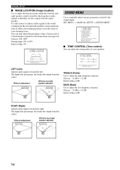
...Adjusts audio signals towards the left and right speakers seems unnatural, such as the beam mode (see page 44). Choices: -12 dB to the sound output. The higher the percentage, the louder the output from the center. A)TONE CONTROL B)BEAM LEVEL C)SUBWOOFER SET D)MUTE LEVEL E)AUDIO DELAY F)ROOM EQ... G)DD/DTS Dynamic Range [ ]/[ ]:Up/Down [ENTER]:Enter ■ TONE CONTROL (Tone control) You can only adjust this feature to redirect audio signals if the sound coming from the center speaker. Choices: -12 dB to ...
...Adjusts audio signals towards the left and right speakers seems unnatural, such as the beam mode (see page 44). Choices: -12 dB to the sound output. The higher the percentage, the louder the output from the center. A)TONE CONTROL B)BEAM LEVEL C)SUBWOOFER SET D)MUTE LEVEL E)AUDIO DELAY F)ROOM EQ... G)DD/DTS Dynamic Range [ ]/[ ]:Up/Down [ENTER]:Enter ■ TONE CONTROL (Tone control) You can only adjust this feature to redirect audio signals if the sound coming from the center speaker. Choices: -12 dB to ...

Owner's Manual
Page 79
...low-frequency signals from the listening position. This setting is displayed. When setting the surround right speaker, the test tone is output from the surround left speaker and subwoofer. In this case, NONE is effective only when this parameter depending on the beam mode ...channel according to manually adjust various subwoofer settings. This setting also determines the routing of the subwoofer from other channels are only added to 15.0 m Initial setting: 3.0 m 75 CROSS OVER (Cross over (cut-off) frequency for this unit decodes Dolby Digital or DTS signals. Choices: -20...
...low-frequency signals from the listening position. This setting is displayed. When setting the surround right speaker, the test tone is output from the surround left speaker and subwoofer. In this case, NONE is effective only when this parameter depending on the beam mode ...channel according to manually adjust various subwoofer settings. This setting also determines the routing of the subwoofer from other channels are only added to 15.0 m Initial setting: 3.0 m 75 CROSS OVER (Cross over (cut-off) frequency for this unit decodes Dolby Digital or DTS signals. Choices: -20...


