Owners Manual
Page 2
... of Graphical Symbols The lightning flash with dry cloth. 7 Do not block any ventilation openings. Install in particular, specifies that the cable ground shall be connected to the grounding system of the building, as close to the point of cable entry as practical. 1 Read these instructions. 2 Keep these instructions. 3 Heed all...
... of Graphical Symbols The lightning flash with dry cloth. 7 Do not block any ventilation openings. Install in particular, specifies that the cable ground shall be connected to the grounding system of the building, as close to the point of cable entry as practical. 1 Read these instructions. 2 Keep these instructions. 3 Heed all...
Owners Manual
Page 3
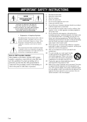
... US customers) 1 IMPORTANT NOTICE: DO NOT MODIFY THIS UNIT! Utilize power outlets that your authority, granted by Yamaha Corporation of assurance that are on different branch (circuit breaker or fuse) circuits or install AC line filter/s. If...Yamaha may cause interference harmful to coaxial type cable. IMPORTANT SAFETY INSTRUCTIONS FCC INFORMATION (for Class "B" digital devices. ii En This equipment generates/uses radio frequencies and, if not installed and used . Failure to follow instructions could void your FCC authorization to use the product. 2 IMPORTANT: When connecting...
... US customers) 1 IMPORTANT NOTICE: DO NOT MODIFY THIS UNIT! Utilize power outlets that your authority, granted by Yamaha Corporation of assurance that are on different branch (circuit breaker or fuse) circuits or install AC line filter/s. If...Yamaha may cause interference harmful to coaxial type cable. IMPORTANT SAFETY INSTRUCTIONS FCC INFORMATION (for Class "B" digital devices. ii En This equipment generates/uses radio frequencies and, if not installed and used . Failure to follow instructions could void your FCC authorization to use the product. 2 IMPORTANT: When connecting...
Owners Manual
Page 4
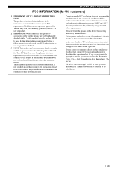
...record the serial number of power. iii En CAUTION: READ THIS BEFORE OPERATING YOUR UNIT. this sound system in them, as it is connected to liquid dripping or splashing. The cabinet should never be exposed to excessive heat such as they may fall onto this unit and/or this... the power supply cable from the outlet, then leave the unit alone. 20 The batteries shall not be opened for future reference. Contact qualified Yamaha service personnel when any reasons. 15 When not planning to obstruct heat radiation. away from a wall outlet or the unit during a lightning storm...
...record the serial number of power. iii En CAUTION: READ THIS BEFORE OPERATING YOUR UNIT. this sound system in them, as it is connected to liquid dripping or splashing. The cabinet should never be exposed to excessive heat such as they may fall onto this unit and/or this... the power supply cable from the outlet, then leave the unit alone. 20 The batteries shall not be opened for future reference. Contact qualified Yamaha service personnel when any reasons. 15 When not planning to obstruct heat radiation. away from a wall outlet or the unit during a lightning storm...
Owners Manual
Page 5
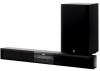
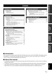
... subwoofer/system control (YAS-70SPX). We hope the "YAS-70" brings you great listening pleasure and satisfaction. ■ About this manual • In this system 7 Placing the center system 7 Connection 9 Connecting the center system and the subwoofer/system control 9 Connecting external components 10 Connecting a Yamaha iPod universal dock 12 Connecting the indoor FM antenna 12 Connecting the power cable...
... subwoofer/system control (YAS-70SPX). We hope the "YAS-70" brings you great listening pleasure and satisfaction. ■ About this manual • In this system 7 Placing the center system 7 Connection 9 Connecting the center system and the subwoofer/system control 9 Connecting external components 10 Connecting a Yamaha iPod universal dock 12 Connecting the indoor FM antenna 12 Connecting the power cable...
Owners Manual
Page 6
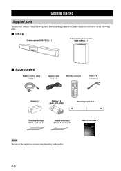
... the supplied accessories varies depending on the models. Before making connections, make sure you received all of the following parts. GETTING STARTED Getting started Supplied parts This product consists of the following parts. ■ Units Center system (YAS-70CU) x 1 Subwoofer/system control (YAS-70SPX) x 1 ■ Accessories System control cable (4 m) x 1 Spacer x 2 Speaker cable (4 m) x 2 Remote...
... the supplied accessories varies depending on the models. Before making connections, make sure you received all of the following parts. GETTING STARTED Getting started Supplied parts This product consists of the following parts. ■ Units Center system (YAS-70CU) x 1 Subwoofer/system control (YAS-70SPX) x 1 ■ Accessories System control cable (4 m) x 1 Spacer x 2 Speaker cable (4 m) x 2 Remote...
Owners Manual
Page 11
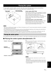
... tape Fig. Be careful when placing or moving this unit away from falling. Center system (YAS-70CU) Subwoofer/system control (YAS-70SPX) Center system (YAS-70CU) Place the center system above /beneath a TV Example 1: Above your installation environment, connections with the wall. INPUT - After deciding the layout, follow the procedure below to prevent the... TV so that you need to place this system. Also produces center channel sounds (dialogues or vocal sounds) and surround channel sounds effectively using the Yamaha Air Surround system.
... tape Fig. Be careful when placing or moving this unit away from falling. Center system (YAS-70CU) Subwoofer/system control (YAS-70SPX) Center system (YAS-70CU) Place the center system above /beneath a TV Example 1: Above your installation environment, connections with the wall. INPUT - After deciding the layout, follow the procedure below to prevent the... TV so that you need to place this system. Also produces center channel sounds (dialogues or vocal sounds) and surround channel sounds effectively using the Yamaha Air Surround system.

Owners Manual
Page 12
... then install the commercially available screws at the marks. Using clamps other than specified screws, such as plaster or veneered woods. Yamaha will bear no responsibility for any accidents caused by a qualified contractor or dealer personnel. Tapes or thumbtacks Mark Installing the cables ...cables do not loosen. Diameter: 7.5 mm or more (#8, 9/32" or more )). Do not attach the center system to fall . • When connecting the center system, fix the speaker cables in personal injury. 1 Attach the supplied mounting template on a wall, all installation work . Doing so may...
... then install the commercially available screws at the marks. Using clamps other than specified screws, such as plaster or veneered woods. Yamaha will bear no responsibility for any accidents caused by a qualified contractor or dealer personnel. Tapes or thumbtacks Mark Installing the cables ...cables do not loosen. Diameter: 7.5 mm or more (#8, 9/32" or more )). Do not attach the center system to fall . • When connecting the center system, fix the speaker cables in personal injury. 1 Attach the supplied mounting template on a wall, all installation work . Doing so may...
Owners Manual
Page 13
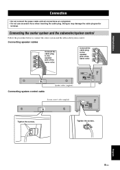
...R L SPEAKERS Tighten the screws. Tighten the screws. Doing so may damage the cable plug and/or terminal. Connecting speaker cables Connect the cable plug to the speaker jack of the same color. Connecting the center system and the subwoofer/system control Follow the procedure below to... connect the center system and the subwoofer/system control. PREPARATION Connection • Do not connect the power cable until all connections are completed. • ...
...R L SPEAKERS Tighten the screws. Tighten the screws. Doing so may damage the cable plug and/or terminal. Connecting speaker cables Connect the cable plug to the speaker jack of the same color. Connecting the center system and the subwoofer/system control Follow the procedure below to... connect the center system and the subwoofer/system control. PREPARATION Connection • Do not connect the power cable until all connections are completed. • ...

Owners Manual
Page 14
... The subwoofer/system control has 3 digital/analog input jacks (optical digital x 1, coaxial digital x 1, analog x 1). Before connecting your external components, check the output jacks of the components and be sure to use correct connection cables. ■ Digital connection Notes • The digital jacks of this system support PCM, Dolby Digital, and DTS signal system...
... The subwoofer/system control has 3 digital/analog input jacks (optical digital x 1, coaxial digital x 1, analog x 1). Before connecting your external components, check the output jacks of the components and be sure to use correct connection cables. ■ Digital connection Notes • The digital jacks of this system support PCM, Dolby Digital, and DTS signal system...

Owners Manual
Page 15
PREPARATION ■ Analog connection [INPUT 3] ANALOG jacks Example1: TV TV L R AUDIO OUTPUT Example 2: VCR or video camera VCR or video camera, etc. Video camera AUDIO OUTPUT L R Connection SYSTEM CONNECTOR FM 75Ω UNBAL 3 L ANTENNA 1 2 DOCK R ANALOG INPUT OPTICAL COAXIAL R L SPEAKERS SYSTEM CONNECTOR FM 75Ω UNBAL 3 L ANTENNA 1 2 DOCK R ANALOG INPUT OPTICAL COAXIAL R L SPEAKERS English 11 En VCR etc. with no digital output.
PREPARATION ■ Analog connection [INPUT 3] ANALOG jacks Example1: TV TV L R AUDIO OUTPUT Example 2: VCR or video camera VCR or video camera, etc. Video camera AUDIO OUTPUT L R Connection SYSTEM CONNECTOR FM 75Ω UNBAL 3 L ANTENNA 1 2 DOCK R ANALOG INPUT OPTICAL COAXIAL R L SPEAKERS SYSTEM CONNECTOR FM 75Ω UNBAL 3 L ANTENNA 1 2 DOCK R ANALOG INPUT OPTICAL COAXIAL R L SPEAKERS English 11 En VCR etc. with no digital output.
Owners Manual
Page 16
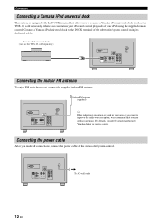
...75Ω UNBAL 3 L ANTENNA 1 2 DOCK R ANALOG INPUT OPTICAL COAXIAL R L SPEAKERS Connecting the indoor FM antenna To enjoy FM radio broadcast, connect the supplied indoor FM antenna. Connection Connecting a Yamaha iPod universal dock This system is weak in your area or you want to improve the radio ...wave reception, we recommend that allows you to the DOCK terminal of the subwoofer/system control. Connect a Yamaha iPod universal dock to connect a Yamaha iPod universal dock (such as the YDS-10, sold separately) where you can station your iPod and control...
...75Ω UNBAL 3 L ANTENNA 1 2 DOCK R ANALOG INPUT OPTICAL COAXIAL R L SPEAKERS Connecting the indoor FM antenna To enjoy FM radio broadcast, connect the supplied indoor FM antenna. Connection Connecting a Yamaha iPod universal dock This system is weak in your area or you want to improve the radio ...wave reception, we recommend that allows you to the DOCK terminal of the subwoofer/system control. Connect a Yamaha iPod universal dock to connect a Yamaha iPod universal dock (such as the YDS-10, sold separately) where you can station your iPod and control...
Owners Manual
Page 17
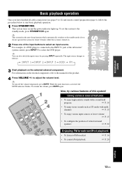
... STANDBY/ON. y To turn off the volume temporarily, press MUTE. For information on the selected external component. For example, if a DVD player is connected to the INPUT 1 jack of virtual surround speakers ☞ P. 22 MEMORY SW PR/ETSUENTE AU/MTAON'L HT R Enjoying FM broadcast/iPod playback •...; To listen to the standby mode if you have finished all cable connections (see pages 9 to 12) and remote control preparation (page 6), follow the procedure below to the manual for about 24 hours while ...
... STANDBY/ON. y To turn off the volume temporarily, press MUTE. For information on the selected external component. For example, if a DVD player is connected to the INPUT 1 jack of virtual surround speakers ☞ P. 22 MEMORY SW PR/ETSUENTE AU/MTAON'L HT R Enjoying FM broadcast/iPod playback •...; To listen to the standby mode if you have finished all cable connections (see pages 9 to 12) and remote control preparation (page 6), follow the procedure below to the manual for about 24 hours while ...
Owners Manual
Page 24
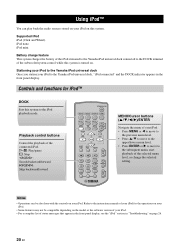
... features may not be also done with the controls on this system. Playback control buttons Control the playback of the connected iPod. MENU/Cursor buttons (S / T / W / X)/ENTER Navigate the menu of your iPod. Supported iPod ...iPod mini Battery charge feature This system charges the battery of the iPod stationed to the Yamaha iPod universal dock connected to the DOCK terminal of the subwoofer/system control while this system to the iPod ...the software version of your iPod to the Yamaha iPod universal dock, "iPod connected" and the DOCK indicator appears in "Troubleshooting" on .
... features may not be also done with the controls on this system. Playback control buttons Control the playback of the connected iPod. MENU/Cursor buttons (S / T / W / X)/ENTER Navigate the menu of your iPod. Supported iPod ...iPod mini Battery charge feature This system charges the battery of the iPod stationed to the Yamaha iPod universal dock connected to the DOCK terminal of the subwoofer/system control while this system to the iPod ...the software version of your iPod to the Yamaha iPod universal dock, "iPod connected" and the DOCK indicator appears in "Troubleshooting" on .
Owners Manual
Page 30
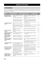
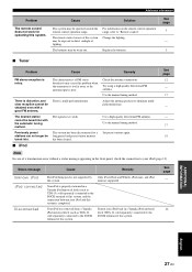
...digital or highfrequency equipment produces noises. The volume may be shorted. The input source or input setting may be incorrect. The cables may be connected improperly. Make sure the power cable is any low tone signal. Press sound field program button to stereo sounds without the sound field effect... does not support signals outside that does not contain any problem with this system, and then consult the nearest authorized Yamaha dealer or service center. You may be connected improperly. This system may be set to the standby mode, and then disconnect the power cable...
...digital or highfrequency equipment produces noises. The volume may be shorted. The input source or input setting may be incorrect. The cables may be connected improperly. Make sure the power cable is any low tone signal. Press sound field program button to stereo sounds without the sound field effect... does not support signals outside that does not contain any problem with this system, and then consult the nearest authorized Yamaha dealer or service center. You may be connected improperly. This system may be set to the standby mode, and then disconnect the power cable...
Owners Manual
Page 31
... page 12 - 17 - - 17 18 Note In case of a transmission error without a status message appearing in a Yamaha iPod universal dock (such as YDS-10, sold separately) connected to the DOCK terminal of this system. Your iPod is completed. Station your iPod (page 12). The batteries may be... INFORMATION English 27 En Set preset stations again. Your iPod was removed from a Yamaha iPod universal dock (such as YDS-10, sold separately) connected to the DOCK terminal of this system, and the connection between your iPod and this system is properly stationed in the front panel, check ...
... page 12 - 17 - - 17 18 Note In case of a transmission error without a status message appearing in a Yamaha iPod universal dock (such as YDS-10, sold separately) connected to the DOCK terminal of this system. Your iPod is completed. Station your iPod (page 12). The batteries may be... INFORMATION English 27 En Set preset stations again. Your iPod was removed from a Yamaha iPod universal dock (such as YDS-10, sold separately) connected to the DOCK terminal of this system, and the connection between your iPod and this system is properly stationed in the front panel, check ...


