
Owner's Manual
Page 2
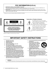
.... WARNING TO REDUCE THE RISK OF FIRE OR ELECTRIC SHOCK, DO NOT EXPOSE THIS APPARATUS TO RAIN OR MOISTURE. (98-6500) 2 XM4180/XM4080/XH200 Owner's Manual IMPORTANT: When connecting this product to accessories and/or another product use this product MUST be of sufficient...amplifiers) that may void your FCC authorization to products distributed by Yamaha may be used , use this apparatus during lightning storms or when unused for replacement of the obsolete outlet. 10 Protect the power cord from being walked on the top of the polarized or grounding-type...
.... WARNING TO REDUCE THE RISK OF FIRE OR ELECTRIC SHOCK, DO NOT EXPOSE THIS APPARATUS TO RAIN OR MOISTURE. (98-6500) 2 XM4180/XM4080/XH200 Owner's Manual IMPORTANT: When connecting this product to accessories and/or another product use this product MUST be of sufficient...amplifiers) that may void your FCC authorization to products distributed by Yamaha may be used , use this apparatus during lightning storms or when unused for replacement of the obsolete outlet. 10 Protect the power cord from being walked on the top of the polarized or grounding-type...
Owner's Manual
Page 3
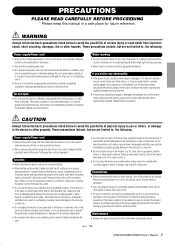
...still flowing to the product at the front and rear to prevent the internal temperature from the AC outlet when cleaning the device. (5)-4 1/2 XM4180/XM4080/XH200 Owner's Manual 3 1 If this device should appear to be sure to connect the ground screw to a confirmed ground point before... make sure that the AC outlet you are not limited to, the following : Power supply/Power cord • Remove the electric plug from the outlet when the device is not to be caused by qualified Yamaha service personnel. • If this device is adequate space between the device and ...
...still flowing to the product at the front and rear to prevent the internal temperature from the AC outlet when cleaning the device. (5)-4 1/2 XM4180/XM4080/XH200 Owner's Manual 3 1 If this device should appear to be sure to connect the ground screw to a confirmed ground point before... make sure that the AC outlet you are not limited to, the following : Power supply/Power cord • Remove the electric plug from the outlet when the device is not to be caused by qualified Yamaha service personnel. • If this device is adequate space between the device and ...
Owner's Manual
Page 4
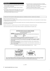
...for explanatory purposes only, and may not correspond with the letter N or coloured BLACK. Handling caution • When turning on the AC power in use. Then have been manufactured in this can be connected to the terminal in any gaps or openings on the device (vents, ...to the terminal which is coloured BLUE must be connected to the device, or data that have the device inspected by Yamaha-Kemble Music (U.K.) Ltd. (3 wires) XM4180 XH200 This mark indicates a dangerous electrically live terminal. The performance of their respective owners. The wire which is marked with...
...for explanatory purposes only, and may not correspond with the letter N or coloured BLACK. Handling caution • When turning on the AC power in use. Then have been manufactured in this can be connected to the terminal in any gaps or openings on the device (vents, ...to the terminal which is coloured BLUE must be connected to the device, or data that have the device inspected by Yamaha-Kemble Music (U.K.) Ltd. (3 wires) XM4180 XH200 This mark indicates a dangerous electrically live terminal. The performance of their respective owners. The wire which is marked with...

Owner's Manual
Page 5
... Specifications 13 MONITOR/REMOTE PIN layout 14 Current Draw 15 Dimensions 16 Block Diagram 17 XM4180/XM4080/XH200 Owner's Manual 5 3 Introduction Thank you for purchasing a Yamaha XM4180, XM4080 or XH200 Power Amplifier. Main features include On the XM4180/XM4080: • Four separate amplifier sections allows the unit to multiple high-impedance...
... Specifications 13 MONITOR/REMOTE PIN layout 14 Current Draw 15 Dimensions 16 Block Diagram 17 XM4180/XM4080/XH200 Owner's Manual 5 3 Introduction Thank you for purchasing a Yamaha XM4180, XM4080 or XH200 Power Amplifier. Main features include On the XM4180/XM4080: • Four separate amplifier sections allows the unit to multiple high-impedance...
Owner's Manual
Page 6
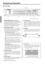
...er is set over a range of this happens, the limiter is ready for normal operation. The POWER indicator lights up when its output exceeds a certain amount (2V rms on the XM4180/ XM4080, 4V rms on the amplifier. The protection system activates in air from the ...64257;er is turned on The protection system activates for the C/D pair, channel C is the main POWER switch. Press to turn on the XH200.) 6 XM4180/XM4080/XH200 Owner's Manual 5 * The illustration shows model XM4180. 5 VOLUME controls The channel volume controls have click detents for ways to 0 dB. Controls and ...
...er is set over a range of this happens, the limiter is ready for normal operation. The POWER indicator lights up when its output exceeds a certain amount (2V rms on the XM4180/ XM4080, 4V rms on the amplifier. The protection system activates in air from the ...64257;er is turned on The protection system activates for the C/D pair, channel C is the main POWER switch. Press to turn on the XH200.) 6 XM4180/XM4080/XH200 Owner's Manual 5 * The illustration shows model XM4180. 5 VOLUME controls The channel volume controls have click detents for ways to 0 dB. Controls and ...
Owner's Manual
Page 7
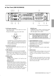
...both to "MONITOR/ REMOTE PIN layout" on the label at the top of pair C/D. XM4180/XM4080/XH200 Owner's Manual 7 5 i.e., channel A of pair A/B, and channel C of the unit. Refer to the channel A power amp and the channel B power amp. Note: When in the pair is used to connect input signals. 3 HPF switches... (earth) or to connect to the chassis of a mixer, preamp, or other plug of the AC cable to an AC outlet that meets the power supply conditions printed on page 14. 6 SPEAKERS terminals These 5-way binding posts are wired as a single mono amplifier. (The same applies ...
...both to "MONITOR/ REMOTE PIN layout" on the label at the top of pair C/D. XM4180/XM4080/XH200 Owner's Manual 7 5 i.e., channel A of pair A/B, and channel C of the unit. Refer to the channel A power amp and the channel B power amp. Note: When in the pair is used to connect input signals. 3 HPF switches... (earth) or to connect to the chassis of a mixer, preamp, or other plug of the AC cable to an AC outlet that meets the power supply conditions printed on page 14. 6 SPEAKERS terminals These 5-way binding posts are wired as a single mono amplifier. (The same applies ...
Owner's Manual
Page 8
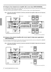
... signal Speaker Speaker +- +- +- +- Speaker * The illustration shows model XM4180. 6 Connect B and C Speaker Speaker * The illustration shows model XM4180. ● Using as a two-channel amplifier with a mono input for high-power applications (XM4180/XM4080) By connecting input terminals B and C with a proper cable, and...A/B and C/D to BRIDGE, you can use the unit as a two-channel high-power mono amplifier. Make sure not to input any signal to the D terminal. Connect B and C 8 XM4180/XM4080/XH200 Owner's Manual + - Make sure not to input any signal to the...
... signal Speaker Speaker +- +- +- +- Speaker * The illustration shows model XM4180. 6 Connect B and C Speaker Speaker * The illustration shows model XM4180. ● Using as a two-channel amplifier with a mono input for high-power applications (XM4180/XM4080) By connecting input terminals B and C with a proper cable, and...A/B and C/D to BRIDGE, you can use the unit as a two-channel high-power mono amplifier. Make sure not to input any signal to the D terminal. Connect B and C 8 XM4180/XM4080/XH200 Owner's Manual + - Make sure not to input any signal to the...
Owner's Manual
Page 10
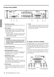
... the AC cable to an AC outlet that can connect up to 200 W. You can connect speakers with a rated input of speakers that meets the power supply conditions printed on page 14. 5 SPEAKERS terminals This unit includes barrier strip terminals, which are wired as shown below 40Hz or 80Hz are fi... at the top of up to ten speakers 10W 10W 10W Rated input 10W 10W 10W 10 W x 20 speakers (200W) 10 W x 20 speakers (200W) 10 XM4180/XM4080/XH200 Owner's Manual 8
... the AC cable to an AC outlet that can connect up to 200 W. You can connect speakers with a rated input of speakers that meets the power supply conditions printed on page 14. 5 SPEAKERS terminals This unit includes barrier strip terminals, which are wired as shown below 40Hz or 80Hz are fi... at the top of up to ten speakers 10W 10W 10W Rated input 10W 10W 10W 10 W x 20 speakers (200W) 10 W x 20 speakers (200W) 10 XM4180/XM4080/XH200 Owner's Manual 8
Owner's Manual
Page 12
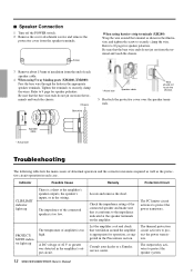
... the Precautions section. A DC voltage of amplifier is appropriate for speaker polarities. The PC limiter circuit activates to protect the power transistors. Indicator Possible Cause Remedy Protection Circuit CLIP/LIMIT indicator lights up The temperature of ±2 V or greater was detected in each... relay activates to securely clamp the wires. Tighten the terminals to protect the speaker system. 12 XM4180/XM4080/XH200 Owner's Manual 10 Consult your dealer or a Yamaha service center. Let the amplifier cool and check that the bare wire ends do not...
... the Precautions section. A DC voltage of amplifier is appropriate for speaker polarities. The PC limiter circuit activates to protect the power transistors. Indicator Possible Cause Remedy Protection Circuit CLIP/LIMIT indicator lights up The temperature of ±2 V or greater was detected in each... relay activates to securely clamp the wires. Tighten the terminals to protect the speaker system. 12 XM4180/XM4080/XH200 Owner's Manual 10 Consult your dealer or a Yamaha service center. Let the amplifier cool and check that the bare wire ends do not...
Owner's Manual
Page 13
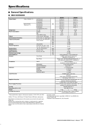
... descriptions in EN55103-1 and EN55103-2. max Front Panel Rear Panel INPUT SPEAKERS MONITOR/REMOTE POWER/STANDBY SIGNAL CLIP/LIMIT PROTECT/MUTE MIN TYP TYP TYP TYP MAX MAX MAX TYP MIN MIN MIN MAX MIN TYP MIN TYP XM4180 210 W x 4 250 W x 4 500 W x 2 180 W x 4 230 W x 4 460 W x 2 300 W x 2 30 dB ...same in every locale, please check with your Yamaha dealer. Specifications ■ General Specifications ● XM4180/XM4080 Output Power* 1 kHz, THD+N= 1 % 20 Hz-20 kHz THD+N= 0.1 % Voltage Gain Power Consumption THD+N Intermodulation Distortion Frequency Response SN Ratio...
... descriptions in EN55103-1 and EN55103-2. max Front Panel Rear Panel INPUT SPEAKERS MONITOR/REMOTE POWER/STANDBY SIGNAL CLIP/LIMIT PROTECT/MUTE MIN TYP TYP TYP TYP MAX MAX MAX TYP MIN MIN MIN MAX MIN TYP MIN TYP XM4180 210 W x 4 250 W x 4 500 W x 2 180 W x 4 230 W x 4 460 W x 2 300 W x 2 30 dB ...same in every locale, please check with your Yamaha dealer. Specifications ■ General Specifications ● XM4180/XM4080 Output Power* 1 kHz, THD+N= 1 % 20 Hz-20 kHz THD+N= 0.1 % Voltage Gain Power Consumption THD+N Intermodulation Distortion Frequency Response SN Ratio...
Owner's Manual
Page 14
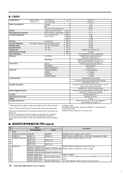
...LEVEL CH A -33.2 dB of 120V, 230V and 240V. 0 dBu=0.775 Vrms, Half Power=1/2 Output Power (3 dB below rated power) Specifications and descriptions in every locale, please check with your Yamaha dealer. Clip limiting : THD ≥ 0.5 % Thermal: Cuts the output (when heatsink ...input 600 Ω shunt Att. reserves the right to rated power supplies of Speaker Output Level, RL=7.5 kΩ, Zo=300 Ω 14 XM4180/XM4080/XH200 Owner's Manual 42 ● XH200 Output Power* Power Consumption THD+N Intermodulation Distortion Frequency Response SN Ratio Channel Separation ...
...LEVEL CH A -33.2 dB of 120V, 230V and 240V. 0 dBu=0.775 Vrms, Half Power=1/2 Output Power (3 dB below rated power) Specifications and descriptions in every locale, please check with your Yamaha dealer. Clip limiting : THD ≥ 0.5 % Thermal: Cuts the output (when heatsink ...input 600 Ω shunt Att. reserves the right to rated power supplies of Speaker Output Level, RL=7.5 kΩ, Zo=300 Ω 14 XM4180/XM4080/XH200 Owner's Manual 42 ● XH200 Output Power* Power Consumption THD+N Intermodulation Distortion Frequency Response SN Ratio Channel Separation ...
Owner's Manual
Page 15
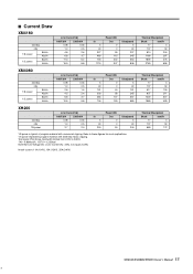
... 34 517 130 837 211 1220 307 1980 499 Thermal Dissipation Btu/h kcal/h 17 4 137 34 683 172 XM4180/XM4080/XH200 Owner's Manual 15 43 ■ Current Draw XM4180 standby idle 1/8 power 8Ω/ch 4Ω/ch 1/3 power 8Ω/ch 4Ω/ch Line Current (A) 100/120V 230/240V 0.08 0.04 1.0 0.5 4.8 2.6 6.8 3.7 11.3 6.2 15.9 8.8 In 5 40 327...
... 34 517 130 837 211 1220 307 1980 499 Thermal Dissipation Btu/h kcal/h 17 4 137 34 683 172 XM4180/XM4080/XH200 Owner's Manual 15 43 ■ Current Draw XM4180 standby idle 1/8 power 8Ω/ch 4Ω/ch 1/3 power 8Ω/ch 4Ω/ch Line Current (A) 100/120V 230/240V 0.08 0.04 1.0 0.5 4.8 2.6 6.8 3.7 11.3 6.2 15.9 8.8 In 5 40 327...
Owner's Manual
Page 17
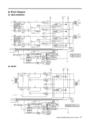
... MUTE PS PROTECTION TEMP DC MUTE PS PROTECTION TEMP OUTPUT CH A (+) BRIDGE (-) BRIDGE CH B XM4180[+34dBu] XM4080[+30dBu] OUTPUT CH C (+) BRIDGE (-) BRIDGE CH D GR/OR (GR+RE) POWER SW POWER/STANDBY SUB TRANS +15V MAIN TRANS RELAY DRIVE J,H,B,W,K,C distination U,V,T, distination SWITCHING DRIVER SHUTDOWN CIRCUIT OVERCURRENT DETECT... DETECT +15V +24 +15 +5V -15V -15 15G -24 +BH +BL -BL -BH FAN Maximum Output Power (20 -20 kHz THD+N 0.1 %) MODEL 8 Ω XM4180 180 W x 4 XM4080 80 W x 4 BGND CLIP x2 RE PROTECTION x2 RE SIGNAL x2 GR CH A INPUT [+4dBu] CH B 70V [+1dBu] 100V...
... MUTE PS PROTECTION TEMP DC MUTE PS PROTECTION TEMP OUTPUT CH A (+) BRIDGE (-) BRIDGE CH B XM4180[+34dBu] XM4080[+30dBu] OUTPUT CH C (+) BRIDGE (-) BRIDGE CH D GR/OR (GR+RE) POWER SW POWER/STANDBY SUB TRANS +15V MAIN TRANS RELAY DRIVE J,H,B,W,K,C distination U,V,T, distination SWITCHING DRIVER SHUTDOWN CIRCUIT OVERCURRENT DETECT... DETECT +15V +24 +15 +5V -15V -15 15G -24 +BH +BL -BL -BH FAN Maximum Output Power (20 -20 kHz THD+N 0.1 %) MODEL 8 Ω XM4180 180 W x 4 XM4080 80 W x 4 BGND CLIP x2 RE PROTECTION x2 RE SIGNAL x2 GR CH A INPUT [+4dBu] CH B 70V [+1dBu] 100V...


