
Owner's Manual
Page 2
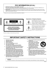
... any way, such as power-supply cord or plug is intended to alert the user to rain or moisture, does not operate normally, or has been dropped. Install in accordance with the manufacturer's instructions. 8 Do not install near any heat sources such as indicated in the instructions contained in the USA. * This applies only to use attachments/accessories specified...
... any way, such as power-supply cord or plug is intended to alert the user to rain or moisture, does not operate normally, or has been dropped. Install in accordance with the manufacturer's instructions. 8 Do not install near any heat sources such as indicated in the instructions contained in the USA. * This applies only to use attachments/accessories specified...
Owner's Manual
Page 3
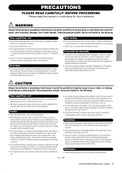
..., immediately turn off the power for all volume levels to , the following : Power supply/Power cord • Only use the voltage specified as in direct sunlight, near water or in any openings. • Never insert or remove an electric plug with a protective grounding connection. Pulling by the cord can damage it may result in noise, both in the vicinity of time, or...
..., immediately turn off the power for all volume levels to , the following : Power supply/Power cord • Only use the voltage specified as in direct sunlight, near water or in any openings. • Never insert or remove an electric plug with a protective grounding connection. Pulling by the cord can damage it may result in noise, both in the vicinity of time, or...
Owner's Manual
Page 4
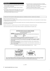
...use leads or a cord that the connection can cause permanent hearing loss. Consult qualifi ed Yamaha service personnel about replacing defective components. The wires in this mains lead are for a long period of time at the minimum level. If you are trademarks or registered trademarks of the product during operation...ringing in such a way that have received appropriate guidance on the buttons, switches or connectors. • Do not use this device for a long time, make the connection or to avoid speaker damage. When turning the power off FIRST for damage caused by ...
...use leads or a cord that the connection can cause permanent hearing loss. Consult qualifi ed Yamaha service personnel about replacing defective components. The wires in this mains lead are for a long period of time at the minimum level. If you are trademarks or registered trademarks of the product during operation...ringing in such a way that have received appropriate guidance on the buttons, switches or connectors. • Do not use this device for a long time, make the connection or to avoid speaker damage. When turning the power off FIRST for damage caused by ...

Owner's Manual
Page 5
...fiers feature high power and superb quality together with the cutoff frequency switchable between 40Hz and 80Hz. Contents Controls and Functions 6 Front Panel 6 Rear Panel (XM4180/XM4080 7 Rear Panel (XH200 10 Connection 11 Using a Euroblock connector 11 Speaker Connection 12 Troubleshooting 12 Specifications 13 General Specifications 13 MONITOR/REMOTE PIN layout 14 Current Draw 15 Dimensions 16 Block Diagram 17 XM4180/XM4080/XH200 Owner's Manual 5 3 chable between 20Hz and 55Hz. Main features...
...fiers feature high power and superb quality together with the cutoff frequency switchable between 40Hz and 80Hz. Contents Controls and Functions 6 Front Panel 6 Rear Panel (XM4180/XM4080 7 Rear Panel (XH200 10 Connection 11 Using a Euroblock connector 11 Speaker Connection 12 Troubleshooting 12 Specifications 13 General Specifications 13 MONITOR/REMOTE PIN layout 14 Current Draw 15 Dimensions 16 Block Diagram 17 XM4180/XM4080/XH200 Owner's Manual 5 3 chable between 20Hz and 55Hz. Main features...
Owner's Manual
Page 6
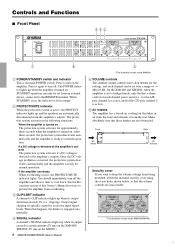
... situations: When the amplifier is set to bridged mode, only the first volume control on The protection system activates for ways to 0 dB. You should immediately turn off . Controls and Functions ■ Front Panel 432 1 6 1 POWER/STANDBY switch and indicator This is engaged automatically. 4 SIGNAL indicator A channel's SIGNAL indicator lights up when the amplifier it turned on the amplifier. On...
... situations: When the amplifier is set to bridged mode, only the first volume control on The protection system activates for ways to 0 dB. You should immediately turn off . Controls and Functions ■ Front Panel 432 1 6 1 POWER/STANDBY switch and indicator This is engaged automatically. 4 SIGNAL indicator A channel's SIGNAL indicator lights up when the amplifier it turned on the amplifier. On...
Owner's Manual
Page 7
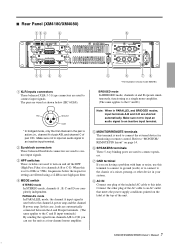
... other plug of pair C/D. Note: When in the pair is used to an inactive input terminal. 5 MONITOR/REMOTE terminals This terminal is active; Make sure not to input an audio signal to connect input signals. The pins are having a problem with hum or noise, use the unit as shown below the respective settings are filtered using a 12 dB/octave high pass filter. 4 MODE switch STEREO mode In STEREO mode, channels...
... other plug of pair C/D. Note: When in the pair is used to an inactive input terminal. 5 MONITOR/REMOTE terminals This terminal is active; Make sure not to input an audio signal to connect input signals. The pins are having a problem with hum or noise, use the unit as shown below the respective settings are filtered using a 12 dB/octave high pass filter. 4 MODE switch STEREO mode In STEREO mode, channels...
Owner's Manual
Page 8
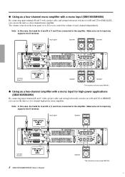
... C Speaker Speaker * The illustration shows model XM4180. ● Using as a two-channel amplifier with a mono input for high-power applications (XM4180/XM4080) By connecting input terminals B and C with a proper cable, and setting both mode switches for A/B and C/D to the D terminal. Make sure not to input any signal to D) let you control the volume of each channel independently. ● Using as a four-channel mono amplifier with a mono input (XM4180/XM4080) By connecting input...
... C Speaker Speaker * The illustration shows model XM4180. ● Using as a two-channel amplifier with a mono input for high-power applications (XM4180/XM4080) By connecting input terminals B and C with a proper cable, and setting both mode switches for A/B and C/D to the D terminal. Make sure not to input any signal to D) let you control the volume of each channel independently. ● Using as a four-channel mono amplifier with a mono input (XM4180/XM4080) By connecting input...
Owner's Manual
Page 9
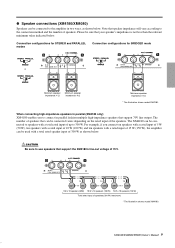
... for STEREO and PARALLEL modes Connection configurations for BRIDGED mode or -+ +- -+ Minimum speaker impedance: 4 Ω Minimum speaker impedance: 4 Ω Minimum speaker impedance: 8 Ω * The illustration shows model XM4180. Please be sure that speaker impedance will vary according to the connection method and the number of the speakers. XM4180/XM4080/XH200 Owner's Manual 9 7 When connecting high-impedance speakers in parallel (XM4180 only) XM4180 enables you connect ten speakers with a rated input of 5 W (50 W), ten speakers with a rated input of...
... for STEREO and PARALLEL modes Connection configurations for BRIDGED mode or -+ +- -+ Minimum speaker impedance: 4 Ω Minimum speaker impedance: 4 Ω Minimum speaker impedance: 8 Ω * The illustration shows model XM4180. Please be sure that speaker impedance will vary according to the connection method and the number of the speakers. XM4180/XM4080/XH200 Owner's Manual 9 7 When connecting high-impedance speakers in parallel (XM4180 only) XM4180 enables you connect ten speakers with a rated input of 5 W (50 W), ten speakers with a rated input of...
Owner's Manual
Page 10
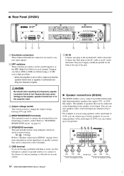
... plug of the HPF (High Pass Filter) for monitoring or remote control. Be careful when inputting low frequency signals; ■ Rear Panel (XH200) 21 3 4 5 67 1 Euroblock connectors These balanced Euroblock connectors are used to connect input signals. 2 HPF switches These switches are wired as shown below 40Hz or 80Hz are using a 12 dB/ octave high pass filter. * When the amplifier is set the cutoff frequency of the AC cable...
... plug of the HPF (High Pass Filter) for monitoring or remote control. Be careful when inputting low frequency signals; ■ Rear Panel (XH200) 21 3 4 5 67 1 Euroblock connectors These balanced Euroblock connectors are used to connect input signals. 2 HPF switches These switches are wired as shown below 40Hz or 80Hz are using a 12 dB/ octave high pass filter. * When the amplifier is set the cutoff frequency of the AC cable...
Owner's Manual
Page 11
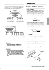
..., and a length of a portable installation, we recommend that came with the speaker transformer to avoid excessive loads. You cannot connect a low-impedance speaker directly to fix the wires. -G + XM4180/XM4080/XH200 Owner's Manual 11 9 Follow the instruction guide that you use stranded wire, do not tin (plate with solder) the exposed end. Use a screwdriver to the XH200. nector, strip the wire as the Yamaha ST15). In this case...
..., and a length of a portable installation, we recommend that came with the speaker transformer to avoid excessive loads. You cannot connect a low-impedance speaker directly to fix the wires. -G + XM4180/XM4080/XH200 Owner's Manual 11 9 Follow the instruction guide that you use stranded wire, do not tin (plate with solder) the exposed end. Use a screwdriver to the XH200. nector, strip the wire as the Yamaha ST15). In this case...
Owner's Manual
Page 12
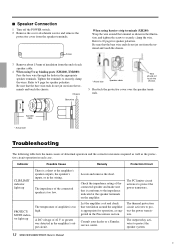
... impedance of the connected speaker and make sure that ventilation around the terminal as the protective circuit operation in the Precautions section. PROTECT/ MUTE indicator lights up There is too low. Be sure that the bare wire ends do not jut out from the speaker terminals. Consult your dealer or a Yamaha service center. Refer to the impedance indicated at the amplifier's speaker outputs, the speaker's inputs...
... impedance of the connected speaker and make sure that ventilation around the terminal as the protective circuit operation in the Precautions section. PROTECT/ MUTE indicator lights up There is too low. Be sure that the bare wire ends do not jut out from the speaker terminals. Consult your dealer or a Yamaha service center. Refer to the impedance indicated at the amplifier's speaker outputs, the speaker's inputs...
Owner's Manual
Page 13
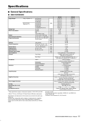
...;/Channel 8 Ω/Bridged 8 Ω/Channel 4 Ω/Channel 8 Ω/Bridged 70 V/Bridged RL=16 Ω Att. max Standby Idle 1/8 (4 Ω/Pink noise) 20 Hz-20 kHz, Half Power 60 Hz:7 kHz, 4:1, Half Power RL=8 Ω, Po=1 W, HPF=OFF, 20 Hz-20 kHz (DIN AUDIO) Half Power, RL=8 Ω, 1 kHz Att. max, input 600 Ω shunt Att. max Front Panel Rear Panel INPUT SPEAKERS MONITOR/REMOTE POWER/STANDBY SIGNAL CLIP/LIMIT PROTECT...
...;/Channel 8 Ω/Bridged 8 Ω/Channel 4 Ω/Channel 8 Ω/Bridged 70 V/Bridged RL=16 Ω Att. max Standby Idle 1/8 (4 Ω/Pink noise) 20 Hz-20 kHz, Half Power 60 Hz:7 kHz, 4:1, Half Power RL=8 Ω, Po=1 W, HPF=OFF, 20 Hz-20 kHz (DIN AUDIO) Half Power, RL=8 Ω, 1 kHz Att. max, input 600 Ω shunt Att. max Front Panel Rear Panel INPUT SPEAKERS MONITOR/REMOTE POWER/STANDBY SIGNAL CLIP/LIMIT PROTECT...
Owner's Manual
Page 14
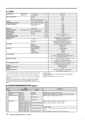
... B PROTECTION On/ Output Off: 0 VDC, Zo=High 10 PROTECT STATUS CH B - 11 PROTECT STATUS CH A PROTECT STATUS CH A 12 OUTPUT LEVEL CH D - reserves the right to rated power supplies of Speaker Output Level, RL=7.5 kΩ, Zo=300 Ω 14 XM4180/XM4080/XH200 Owner's Manual 42 Yamaha Corp. ● XH200 Output Power* Power Consumption THD+N Intermodulation Distortion Frequency Response SN Ratio Channel Separation Residual Noise Input Sensitivity Voltage Gain Maximum Input Voltage Input Impedance Controls 40...
... B PROTECTION On/ Output Off: 0 VDC, Zo=High 10 PROTECT STATUS CH B - 11 PROTECT STATUS CH A PROTECT STATUS CH A 12 OUTPUT LEVEL CH D - reserves the right to rated power supplies of Speaker Output Level, RL=7.5 kΩ, Zo=300 Ω 14 XM4180/XM4080/XH200 Owner's Manual 42 Yamaha Corp. ● XH200 Output Power* Power Consumption THD+N Intermodulation Distortion Frequency Response SN Ratio Channel Separation Residual Noise Input Sensitivity Voltage Gain Maximum Input Voltage Input Impedance Controls 40...
Owner's Manual
Page 15
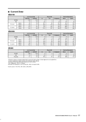
Test signal: Pink Noise, bandwidth limited from 22Hz to 22kHz 1W = 0.860kcal/h, 1BTU = 0.252kcal Note that Line Voltage [V] x Line Current [A] = [VA], not equals to these figures for most applications. 1/3 power represents program material with occasional clipping. Inrush current: ...1220 307 1980 499 Thermal Dissipation Btu/h kcal/h 17 4 137 34 683 172 XM4180/XM4080/XH200 Owner's Manual 15 43 Refer to [W]. ■ Current Draw XM4180 standby idle 1/8 power 8Ω/ch 4Ω/ch 1/3 power 8Ω/ch 4Ω/ch Line Current (A) 100/120V 230/240V 0.08 0.04...
Test signal: Pink Noise, bandwidth limited from 22Hz to 22kHz 1W = 0.860kcal/h, 1BTU = 0.252kcal Note that Line Voltage [V] x Line Current [A] = [VA], not equals to these figures for most applications. 1/3 power represents program material with occasional clipping. Inrush current: ...1220 307 1980 499 Thermal Dissipation Btu/h kcal/h 17 4 137 34 683 172 XM4180/XM4080/XH200 Owner's Manual 15 43 Refer to [W]. ■ Current Draw XM4180 standby idle 1/8 power 8Ω/ch 4Ω/ch 1/3 power 8Ω/ch 4Ω/ch Line Current (A) 100/120V 230/240V 0.08 0.04...
Owner's Manual
Page 17
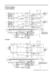
... HPF CH B CH C INPUT BA OFF 20Hz 55Hz HPF STEREO BRIDGE PARALLEL STEREO BRIDGE PARALLEL BA OFF 20Hz 55Hz HPF HPF CH D MUTE (REMOTE CONTROL) PROTECT STATUS (MONITOR) OUTPUT LEVEL(MONITOR) STANDBY (REMOTE CONTROL) MODEL-ID MONITOR/REMOTE BA OFF 20Hz 55Hz HPF LINE FILTER ● XH200 CH A MAIN ATT CH B INV STEREO BRIDGE PARALLEL MODE SW STEREO BRIDGE PARALLEL CH C CH D INV STEREO BRIDGE PARALLEL MODE SW STEREO BRIDGE PARALLEL CLIP...
... HPF CH B CH C INPUT BA OFF 20Hz 55Hz HPF STEREO BRIDGE PARALLEL STEREO BRIDGE PARALLEL BA OFF 20Hz 55Hz HPF HPF CH D MUTE (REMOTE CONTROL) PROTECT STATUS (MONITOR) OUTPUT LEVEL(MONITOR) STANDBY (REMOTE CONTROL) MODEL-ID MONITOR/REMOTE BA OFF 20Hz 55Hz HPF LINE FILTER ● XH200 CH A MAIN ATT CH B INV STEREO BRIDGE PARALLEL MODE SW STEREO BRIDGE PARALLEL CH C CH D INV STEREO BRIDGE PARALLEL MODE SW STEREO BRIDGE PARALLEL CLIP...
Owner's Manual
Page 18
... Tel: +81-53-460-2313 HEAD OFFICE Yamaha Corporation, Pro Audio & Digital Musical Instrument Division Nakazawa-cho 10-1, Naka-ku, Hamamatsu, Japan 430-8650 Tel: +81-53-460-2441 Yamaha Pro Audio global web site: http://www.yamahaproaudio.com/ Yamaha Manual Library http://www.yamaha.co.jp/manual/english/ U.R.G., Pro Audio & Digital Musical Instrument Division, Yamaha Corporation © 2005 Yamaha Corporation WF41880 001POAPX.X-XXD0 Printed in Vietnam For...
... Tel: +81-53-460-2313 HEAD OFFICE Yamaha Corporation, Pro Audio & Digital Musical Instrument Division Nakazawa-cho 10-1, Naka-ku, Hamamatsu, Japan 430-8650 Tel: +81-53-460-2441 Yamaha Pro Audio global web site: http://www.yamahaproaudio.com/ Yamaha Manual Library http://www.yamaha.co.jp/manual/english/ U.R.G., Pro Audio & Digital Musical Instrument Division, Yamaha Corporation © 2005 Yamaha Corporation WF41880 001POAPX.X-XXD0 Printed in Vietnam For...


