Yamaha XP5000 Support and Manuals
Get Help and Manuals for this Yamaha item

View All Support Options Below
Free Yamaha XP5000 manuals!
Problems with Yamaha XP5000?
Ask a Question
Free Yamaha XP5000 manuals!
Problems with Yamaha XP5000?
Ask a Question
Popular Yamaha XP5000 Manual Pages
Owner's Manual - Page 2
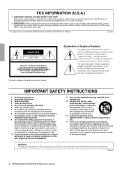
...2 XP7000/XP5000/XP3500/XP2500/XP1000 Owner's Manual Explanation of important operating and maintenance (servicing) instructions in
accordance with the apparatus.
Install in the ...installed as power-supply cord or plug is used . Modifications not expressly approved by Yamaha may void your outlet, consult an electrician for replacement of the obsolete outlet. 10 Protect the power...
Owner's Manual - Page 3
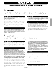
... prevent the possibility of this device for the device.
If some trouble or malfunction occurs, immediately turn off the power switch and disconnect the plug from the AC outlet when cleaning the device.
(5)-4 1/2
XP7000/XP5000/XP3500/XP2500/XP1000 Owner's Manual 3
Maintenance
• Remove the power plug from the outlet. This device has ventilation holes at the...
Owner's Manual - Page 4
..., the device should be made simply and without problem.
(5)-4 2/2
4 XP7000/XP5000/XP3500/XP2500/XP1000 Owner's Manual
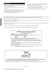
When you unplug the power cord from the AC outlet. Then have been manufactured in such a way that is marked by the letter E or by Yamaha-Kemble Music (U.K.) Ltd. (3 wires)
This mark indicates a dangerous electrically live terminal. Illustrations in this...
Owner's Manual - Page 5
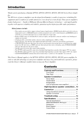
...two internal amps function as high-power mono amplifier 9
High-impedance speaker connections .. 10 Connection 11
Using a Euroblock connector 11 Speaker Connection 11
Troubleshooting 12 Specifications 13
General Specifications 13 MONITOR/REMOTE PIN layout 15 Dimensions 15 Block Diagram 16 Current Draw 18
XP7000/XP5000/XP3500/XP2500/XP1000 Owner's Manual 5 In order to take full advantage...
Owner's Manual - Page 6
...XP5000/XP3500/XP2500/XP1000 Owner's Manual
Air intake
Air exhaust If a DC voltage is not lit. Please be sure that the settings will not be disturbed.
● How to install... is too high.
56
7
* The illustration shows model XP7000.
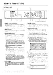
5 SIGNAL indicator
Lights up green when the ...1
3
1 POWER switch and indicator
Press this Owner's Manual for ways to prevent the amplifier from...
Owner's Manual - Page 7
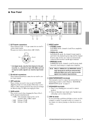
...4dBu: The maximum output power can be obtained when +4dBu is input.
• 26dB: Setting of 26dB • 32dB: Setting of 32dB
5 MODE ...HPF switches
These switches are wired as a single mono amplifier. The pins are used to "MONITOR/ ... XP7000/XP5000/XP3500/XP2500/XP1000 Owner's Manual 7 Speakon type cable plugs can be connected here.
8 GND terminal
If you are having a problem with ...
Owner's Manual - Page 8
... relevant minimum value indicated below.
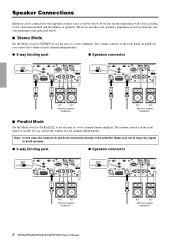
■ Stereo Mode
Set the Mode switch to STEREO to use the unit as shown below. Please be connected to the B terminal.
● 5-way binding post
● Speakon connector
+
-
+
-
4Ω*
4Ω*
* Minimum speaker impedance
8 XP7000/XP5000/XP3500/XP2500/XP1000 Owner's Manual
4Ω*
4Ω*
* Minimum speaker impedance The volume...
Owner's Manual - Page 9
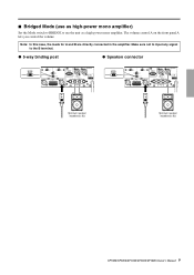
... to use the unit as a high-power mono amplifier.
■ Bridged Mode (use as high-power mono amplifier)
Set the Mode switch to BRIDGE to the B terminal.
● 5-way binding post
● Speakon connector
-
+
Minimum speaker impedance: 8Ω
Minimum speaker impedance: 8Ω
XP7000/XP5000/XP3500/XP2500/XP1000 Owner's Manual 9 Note: In this case, the...
Owner's Manual - Page 10
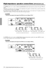
...support the XP7000's line-out voltage of speakers: 625 W (maximum)
10 XP7000/XP5000/XP3500/XP2500/XP1000 Owner's Manual You can connect speakers with a total rated input of up to connect in bridge fashion multiple high-impedance speakers that support...(310W) 15W x 21 speakers (315W)
Total rated input of speakers that support 70V line output.
For example, if you to 625 W. The number of ...
Owner's Manual - Page 11
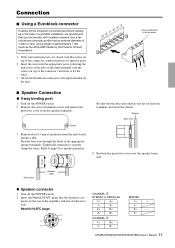
...installation, we recommend that the bare wire ends do not jut out from the end of each speaker cable.
CHANNEL ı
1+
B+
1-
XP7000/XP5000/XP3500/XP2500/XP1000 Owner's Manual 11
Chassis
Bare wire
3 Remove about 15 mm of the ampli...9632; Speaker Connection
● 5-way binding post
1 Turn off the POWER switch. 2 Insert the Neutrik NL4FC plugs into the appropriate ports, ...
Owner's Manual - Page 12
...
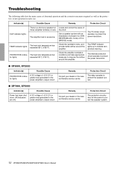
Consult your dealer or the nearest Yamaha service center.
Remedy
Protection Circuit
Consult your dealer or the nearest Yamaha service center. Troubleshooting
The following table lists the main causes of abnormal operation and the corrective measures required as well as the protective circuit operation in the power amplifier's output circuit.
Indicator(s)
Possible...
Owner's Manual - Page 14
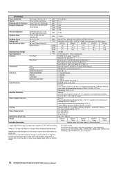
...XP3500 15 kg
XP2500 14 kg
XP1000 12 kg
Security cover (with your Yamaha dealer. operation not restored automatically. (XP7000, XP5000). power supply shutdown (transfomer temp ≥ 130 °C) ; All Models
Power Bandwidth THD+N Intermoduration Distortion Frequency Response
Half Power, THD+N= 0.5 % 20 Hz-20 kHz, Half Power 60 Hz:7 kHz, 4:1, Half Power RL=8 Ω, Po=1 W, HPF=OFF 20...
Owner's Manual - Page 15
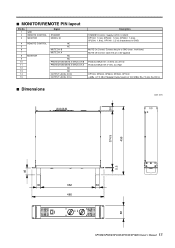
...MODEL ID
4 REMOTE CONTROL
NC
5
NC
6
MUTE CH B
7
MUTE CH A
8 MONITOR
NC
9
NC
10
PROTECTION/MUTE STATUS CH B
11
PROTECTION/MUTE STATUS CH A
12
NC
13
NC
14
OUTPUT LEVEL CH B
15
OUTPUT LEVEL CH A
Description STANDBY Control: Supply 5 VDC, 5 mADC XP7000: 1.0 kΩ, XP5000: 1.2 kΩ, XP3500: 1.5 kΩ, XP2500: 1.8 kΩ, XP1000..., XP5000, XP3500, XP2500, XP1000 +4dBu...
Owner's Manual - Page 16
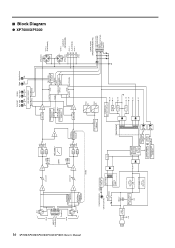
■ Block Diagram
● XP7000/XP5000
16 XP7000/XP5000/XP3500/XP2500/XP1000 Owner's Manual
CH A
XLR 12
3
G
INPUT [+22dBu MAX]
- ...destination
+24
U, A destination
FAN CONTROL CIRCUIT
FAN (R)
+15V
MAIN TRANS
SWITCHING DRIVER
SHUTDOWN CIRCUIT
OVERCURRENT DETECT CIRCUIT
LATCH CIRCUIT
TEMPERATURE +100˚C SENSOR
POWER ON DETECT CIRCUIT
+24
+5V
+5
+15V
+15
-15V
-15
-24...
Owner's Manual - Page 17
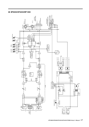
...5way
DATA PORT (MONITOR/REMOTE)
B OUTPUT LEVEL A OUTPUT LEVEL MUTE PROTECT STATUS STANDBY Model ID ● XP3500/XP2500/XP1000 XP7000/XP5000/XP3500/XP2500/XP1000 Owner's Manual 17
CH A
XLR 12
3
G
INPUT
- +
[+22dBu MAX] G
-
...B RY
LIMITER
PA
SP RELAY
MODE
FAN CONTROL CIRCUIT
POWER/STANDBY
GR/OR (GR+RE)
J destination only
POWER SW
Except J destination
FG
RELAY & LED DRIVE CIRCUIT...
Yamaha XP5000 Reviews
We have not received any reviews for Yamaha yet.