

Owner's Manual
Page 1
U B HOME THEATER SOUND SYSTEM TSS-10 INPUT DIGITAL 1 DIGITAL 2 ANALOG MODE DTS DIGITAL PL MOVIE PL MUSIC VOLUME TRIM 7 +6 6 +4 5 +2 4 0 3 -2 2 -4 1 -6 SILENT Active Servo Technology STANDBY/ON TSS-10 HOME THEATER SOUND SYSTEM INPUT MODE REAR S.WOOFER VOLUME MUTE TEST OWNER'S MANUAL
U B HOME THEATER SOUND SYSTEM TSS-10 INPUT DIGITAL 1 DIGITAL 2 ANALOG MODE DTS DIGITAL PL MOVIE PL MUSIC VOLUME TRIM 7 +6 6 +4 5 +2 4 0 3 -2 2 -4 1 -6 SILENT Active Servo Technology STANDBY/ON TSS-10 HOME THEATER SOUND SYSTEM INPUT MODE REAR S.WOOFER VOLUME MUTE TEST OWNER'S MANUAL
Owner's Manual
Page 2
... in the home are complete. 8 Do not operate this system in the standby mode, and disconnect the AC power plug from the wall outlet, grasp the plug; MODEL: Serial No.: The serial number is located on common operating errors before concluding that neither core is designed to the instructions described below . To prevent fire or electrical shock, do not locate this sound system...
... in the home are complete. 8 Do not operate this system in the standby mode, and disconnect the AC power plug from the wall outlet, grasp the plug; MODEL: Serial No.: The serial number is located on common operating errors before concluding that neither core is designed to the instructions described below . To prevent fire or electrical shock, do not locate this sound system...
Owner's Manual
Page 3
...5 CONNECTIONS 7 Connecting audio components 8 Connecting the speakers 9 Connecting the power cable 10 ADJUSTING SPEAKER OUTPUT LEVELS 11 OPERATION PLAYING A SOURCE 12 SELECTING THE SURROUND MODE 13 OPERATION APPENDIX APPENDIX TROUBLESHOOTING 14 GLOSSARY 16 SPECIFICATIONS 17 I About this case, the product has priority. • Some of the illustrations and names of the improvement in operativity ability, and others. G Includes Dolby Digital, Dolby Pro Logic II and DTS Decoders This system can be performed by using the buttons on the package etc. "DTS" and "DTS Digital...
...5 CONNECTIONS 7 Connecting audio components 8 Connecting the speakers 9 Connecting the power cable 10 ADJUSTING SPEAKER OUTPUT LEVELS 11 OPERATION PLAYING A SOURCE 12 SELECTING THE SURROUND MODE 13 OPERATION APPENDIX APPENDIX TROUBLESHOOTING 14 GLOSSARY 16 SPECIFICATIONS 17 I About this case, the product has priority. • Some of the illustrations and names of the improvement in operativity ability, and others. G Includes Dolby Digital, Dolby Pro Logic II and DTS Decoders This system can be performed by using the buttons on the package etc. "DTS" and "DTS Digital...

Owner's Manual
Page 4
... it come into place. 2 The batteries can be set ) Non-skid pads (for the center speaker) (3 sets: 24 pieces) AC adaptor (LSE9802B1540) 3.5 mm stereo mini/ RCA stereo pin cable Stand (for the amplifier unit) Screws (2 pieces) Optical cable Audio pin cable INSTALLING BATTERIES IN THE REMOTE CONTROL Insert the batteries in the operating range of the remote control. • Do not use different types of them immediately. Clean the battery compartment...
... it come into place. 2 The batteries can be set ) Non-skid pads (for the center speaker) (3 sets: 24 pieces) AC adaptor (LSE9802B1540) 3.5 mm stereo mini/ RCA stereo pin cable Stand (for the amplifier unit) Screws (2 pieces) Optical cable Audio pin cable INSTALLING BATTERIES IN THE REMOTE CONTROL Insert the batteries in the operating range of the remote control. • Do not use different types of them immediately. Clean the battery compartment...
Owner's Manual
Page 5
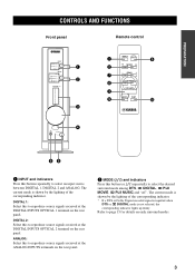
...If a DTS or Dolby Digital encoded signal is inputted when DTS or DIGITAL mode is shown by the lighting of the corresponding indicator. PREPARATION CONTROLS AND FUNCTIONS Front panel Remote control INPUT DIGITAL 1 DIGITAL 2 ANALOG MODE DTS DIGITAL PL MOVIE PL MUSIC VOLUME TRIM 7 +6 6 +4 5 +2 4 0 3 -2 2 -4 1 -6 1 2 3 1 INPUT 5 2 MODE 7 REAR 8 S.WOOFER VOLUME 3 9 MUTE TEST 0 SILENT STANDBY/ON 4 65 1 INPUT and indicators Press this button repeatedly to reproduce source signals received at the DIGITAL INPUTS OPTICAL 1 terminal on the rear panel. DIGITAL 2: Select this to...
...If a DTS or Dolby Digital encoded signal is inputted when DTS or DIGITAL mode is shown by the lighting of the corresponding indicator. PREPARATION CONTROLS AND FUNCTIONS Front panel Remote control INPUT DIGITAL 1 DIGITAL 2 ANALOG MODE DTS DIGITAL PL MOVIE PL MUSIC VOLUME TRIM 7 +6 6 +4 5 +2 4 0 3 -2 2 -4 1 -6 1 2 3 1 INPUT 5 2 MODE 7 REAR 8 S.WOOFER VOLUME 3 9 MUTE TEST 0 SILENT STANDBY/ON 4 65 1 INPUT and indicators Press this button repeatedly to reproduce source signals received at the DIGITAL INPUTS OPTICAL 1 terminal on the rear panel. DIGITAL 2: Select this to...
Owner's Manual
Page 6
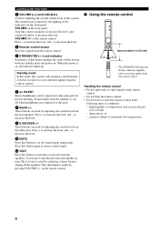
... + to increase the level, and - The adjustment is receiving signals from the remote control. CONTROLS AND FUNCTIONS 3 VOLUME (+/-) and indicators Used for adjusting the sound level from the rear speakers. Press + to decrease the level. 8 S.WOOFER +/- to restore sound output. 0 TEST Press this system between standby mode and power on the front panel. The current level is shown by pressing VOLUME +/- The test tone is cut off when headphones are used for private listening. in turn. VOLUME +/- Handling the remote control • Do...
... + to increase the level, and - The adjustment is receiving signals from the remote control. CONTROLS AND FUNCTIONS 3 VOLUME (+/-) and indicators Used for adjusting the sound level from the rear speakers. Press + to decrease the level. 8 S.WOOFER +/- to restore sound output. 0 TEST Press this system between standby mode and power on the front panel. The current level is shown by pressing VOLUME +/- The test tone is cut off when headphones are used for private listening. in turn. VOLUME +/- Handling the remote control • Do...
Owner's Manual
Page 7
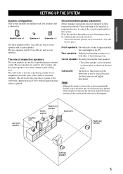
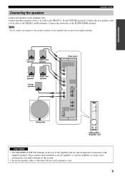
... the monitor as the TV. Place the speakers depending on your listening position or on a wall. (See the next page.) Front speakers: On both sides of the subwoofer channel when a DTS or Dolby Digital encoded source is not so critical because low bass tones are used as rear speakers. Center speaker: Precisely between the front speakers. The position of low frequencies from the front, center and rear surround channels. Amplifier unit x 1 Speaker x 5 Subwoofer x 1 The three speakers with a 10 m cable are...
... the monitor as the TV. Place the speakers depending on your listening position or on a wall. (See the next page.) Front speakers: On both sides of the subwoofer channel when a DTS or Dolby Digital encoded source is not so critical because low bass tones are used as rear speakers. Center speaker: Precisely between the front speakers. The position of low frequencies from the front, center and rear surround channels. Amplifier unit x 1 Speaker x 5 Subwoofer x 1 The three speakers with a 10 m cable are...
Owner's Manual
Page 8
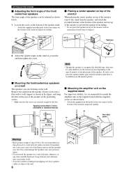
... loose speaker cables, fix them to the wall. 6 This could damage the speakers and cause personal injury. • Do not install the speakers on a wall with soft surface material. Do not mount them to prevent the speaker from the speaker. Long-term use and vibrations may be adjusted as...10؇ pads 10؇ Fastener 2 Adjust the speaker angle on the stand as shown in hardware stores) Ⅵ Mounting the amplifier unit on the supplied stand For improved stability, it is no influence on the monitor picture. Ⅵ Mounting the front/center/rear speakers on a wall The speakers...
... loose speaker cables, fix them to the wall. 6 This could damage the speakers and cause personal injury. • Do not install the speakers on a wall with soft surface material. Do not mount them to prevent the speaker from the speaker. Long-term use and vibrations may be adjusted as...10؇ pads 10؇ Fastener 2 Adjust the speaker angle on the stand as shown in hardware stores) Ⅵ Mounting the amplifier unit on the supplied stand For improved stability, it is no influence on the monitor picture. Ⅵ Mounting the front/center/rear speakers on a wall The speakers...
Owner's Manual
Page 9
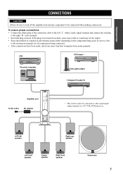
...speaker Right front speaker Subwoofer 7 VCR DVD player Personal computer Video game player TV/digital TV/cable TV To AC outlet Amplifier unit AC adaptor INPUT DIGITAL 1 DIGITAL 2 ANALOG MODE DTS DIGITAL PL MOVIE PL MUSIC VOLUME TRIM 7 +6 6 +4 5 +2 4 0 3 -2 2 -4 1 -6 SILENT Active Servo Technology STANDBY/ON TSS-10 HOME THEATER SOUND SYSTEM * This system cannot be connected to video signal input/ output terminals of the connection cable to the left "L" (white) audio signal terminal and connect the red plug to the instruction manuals for all components being used, be connected...
...speaker Right front speaker Subwoofer 7 VCR DVD player Personal computer Video game player TV/digital TV/cable TV To AC outlet Amplifier unit AC adaptor INPUT DIGITAL 1 DIGITAL 2 ANALOG MODE DTS DIGITAL PL MOVIE PL MUSIC VOLUME TRIM 7 +6 6 +4 5 +2 4 0 3 -2 2 -4 1 -6 SILENT Active Servo Technology STANDBY/ON TSS-10 HOME THEATER SOUND SYSTEM * This system cannot be connected to video signal input/ output terminals of the connection cable to the left "L" (white) audio signal terminal and connect the red plug to the instruction manuals for all components being used, be connected...
Owner's Manual
Page 10
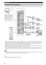
..., connect the video output of dust.) INPUT DIGITAL 1 DIGITAL 2 ANALOG MODE DTS DIGITAL PL MOVIE PL MUSIC VOLUME TRIM 7 +6 6 +4 5 +2 4 0 3 -2 2 -4 1 -6 SILENT STANDBY/ON SPEAKER OUTPUTS FRONT L R REAR (SURROUND) L R CENTER S. which has a 3.5 mm-stereo mini jack only for respective connections. VCR, etc. 3.5 mm stereo mini/RCA stereo pin cable OUTPUT Personal computer, etc. CONNECTIONS Connecting audio components • For connections, use . (This cap prevents the entrance of DVD player to the ANALOG INPUTS audio input terminals on the amplifier unit using an optical cable...
..., connect the video output of dust.) INPUT DIGITAL 1 DIGITAL 2 ANALOG MODE DTS DIGITAL PL MOVIE PL MUSIC VOLUME TRIM 7 +6 6 +4 5 +2 4 0 3 -2 2 -4 1 -6 SILENT STANDBY/ON SPEAKER OUTPUTS FRONT L R REAR (SURROUND) L R CENTER S. which has a 3.5 mm-stereo mini jack only for respective connections. VCR, etc. 3.5 mm stereo mini/RCA stereo pin cable OUTPUT Personal computer, etc. CONNECTIONS Connecting audio components • For connections, use . (This cap prevents the entrance of DVD player to the ANALOG INPUTS audio input terminals on the amplifier unit using an optical cable...
Owner's Manual
Page 11
... with a 10 m cable to this system. • Secure the speaker cables so that they will not catch on the amplifier unit except for connection of the amplifier unit are only designed for the supplied speakers. Connect the subwoofer to the amplifier unit. CONNECTIONS Connecting the speakers Connect the speakers to the SUBWOOFER terminal. WOOFER DC IN 15V DIGITAL INPUTS OPTICAL 1 2 L R ANALOG INPUTS INPUT DIGITAL 1 DIGITAL 2 ANALOG MODE DTS DIGITAL PL MOVIE PL MUSIC VOLUME TRIM 7 +6 6 +4 5 +2 4 0 3 -2 2 -4 1 -6 SILENT STANDBY/ON Amplifier unit CAUTIONS • The SPEAKER OUTPUTS...
... with a 10 m cable to this system. • Secure the speaker cables so that they will not catch on the amplifier unit except for connection of the amplifier unit are only designed for the supplied speakers. Connect the subwoofer to the amplifier unit. CONNECTIONS Connecting the speakers Connect the speakers to the SUBWOOFER terminal. WOOFER DC IN 15V DIGITAL INPUTS OPTICAL 1 2 L R ANALOG INPUTS INPUT DIGITAL 1 DIGITAL 2 ANALOG MODE DTS DIGITAL PL MOVIE PL MUSIC VOLUME TRIM 7 +6 6 +4 5 +2 4 0 3 -2 2 -4 1 -6 SILENT STANDBY/ON Amplifier unit CAUTIONS • The SPEAKER OUTPUTS...
Owner's Manual
Page 12
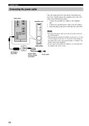
WOOFER DC IN 15V L R ANALOG INPUTS Amplifier unit INPUT DIGITAL 1 DIGITAL 2 ANALOG MODE DTS DIGITAL PL MOVIE PL MUSIC VOLUME TRIM 7 +6 6 +4 5 +2 4 0 3 -2 2 -4 1 -6 SILENT STANDBY/ON Once all connections have been made, check them one more time. Connect the included AC adaptor to the AC adaptor. 3. Notes • Disconnect the power cable if you will not use this system. If the adaptor falls, it from falling. Insert the plug of this system for an...
WOOFER DC IN 15V L R ANALOG INPUTS Amplifier unit INPUT DIGITAL 1 DIGITAL 2 ANALOG MODE DTS DIGITAL PL MOVIE PL MUSIC VOLUME TRIM 7 +6 6 +4 5 +2 4 0 3 -2 2 -4 1 -6 SILENT STANDBY/ON Once all connections have been made, check them one more time. Connect the included AC adaptor to the AC adaptor. 3. Notes • Disconnect the power cable if you will not use this system. If the adaptor falls, it from falling. Insert the plug of this system for an...
Owner's Manual
Page 13
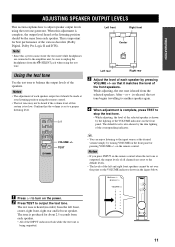
... the selected speakers. The default level is heard (in the figure below. 1 Press to turn on the front panel. Note • Since this adjustment is important for about 2.5 seconds from the SILENT jack when using the test tone generator. INPUT MODE REAR S.WOOFER VOLUME MUTE TEST VOLUME +/- y • You can enjoy listening to unplug the headphones from each speaker by turning VOLUME on the remote control. PL MOVIE PL MUSIC VOLUME TRIM 7 +6 6 +4 5 +2 4 0 3 -2 2 -4 1 -6 INPUT DIGITAL 1 DIGITAL 2 ANALOG MODE DTS DIGITAL PL MOVIE PL MUSIC VOLUME...
... the selected speakers. The default level is heard (in the figure below. 1 Press to turn on the front panel. Note • Since this adjustment is important for about 2.5 seconds from the SILENT jack when using the test tone generator. INPUT MODE REAR S.WOOFER VOLUME MUTE TEST VOLUME +/- y • You can enjoy listening to unplug the headphones from each speaker by turning VOLUME on the remote control. PL MOVIE PL MUSIC VOLUME TRIM 7 +6 6 +4 5 +2 4 0 3 -2 2 -4 1 -6 INPUT DIGITAL 1 DIGITAL 2 ANALOG MODE DTS DIGITAL PL MOVIE PL MUSIC VOLUME...
Owner's Manual
Page 14
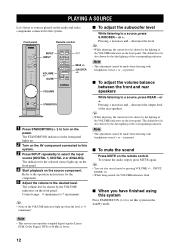
... S.WOOFER - y • While adjusting, the current level is also shown by pressing VOLUME +/-, INPUT, MODE, etc. • While being muted, the VOLUME indicators flash. y • You can reproduce sampled digital signals (Linear PCM, Dolby Digital, DTS) of the VOLUME indicators on the front panel. I To mute the sound Press MUTE on the audio and video components connected to this system Press STANDBY/ON ( ) to turn on the front panel. PLAYING A SOURCE Let's listen to sources played on the remote control. Control range...
... S.WOOFER - y • While adjusting, the current level is also shown by pressing VOLUME +/-, INPUT, MODE, etc. • While being muted, the VOLUME indicators flash. y • You can reproduce sampled digital signals (Linear PCM, Dolby Digital, DTS) of the VOLUME indicators on the front panel. I To mute the sound Press MUTE on the audio and video components connected to this system Press STANDBY/ON ( ) to turn on the front panel. PLAYING A SOURCE Let's listen to sources played on the remote control. Control range...
Owner's Manual
Page 15
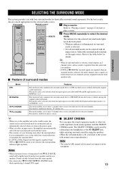
...Front panel Remote control 1 Play a source. INPUT DIGITAL 1 DIGITAL 2 ANALOG MODE DTS DIGITAL PL MOVIE PL MUSIC MODE MODE REAR S.WOOFER MODE / 2 Press MODE repeatedly to what you could experience from the center and rear speakers. • If DTS or DIGITAL encoded signals are inputted when no surround mode is selected, sound output is in the standby mode, the current source and surround mode are memorized and are outputted from the headphone. 13 English y • When you set the amplifier unit in 2channel stereo, and no surround mode is selected, the multi-channel source...
...Front panel Remote control 1 Play a source. INPUT DIGITAL 1 DIGITAL 2 ANALOG MODE DTS DIGITAL PL MOVIE PL MUSIC MODE MODE REAR S.WOOFER MODE / 2 Press MODE repeatedly to what you could experience from the center and rear speakers. • If DTS or DIGITAL encoded signals are inputted when no surround mode is selected, sound output is in the standby mode, the current source and surround mode are memorized and are outputted from the headphone. 13 English y • When you set the amplifier unit in 2channel stereo, and no surround mode is selected, the multi-channel source...
Owner's Manual
Page 16
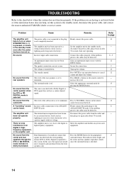
... the problem persists, the cables may be heard. Firmly connect the audio plugs to increase the level. The power cable is not connected or the plug is turned down. Connect the cables properly. Select the appropriate surround mode by a power supply with the corresponding format (DTS or Dolby Digital) is too close to the ANALOG INPUTS jacks. Turn up the volume. Select an appropriate input source with a Dolby Digital or DTS signal does not have a center channel signal. Problem Cause Remedy Refer to page The amplifier unit...
... the problem persists, the cables may be heard. Firmly connect the audio plugs to increase the level. The power cable is not connected or the plug is turned down. Connect the cables properly. Select the appropriate surround mode by a power supply with the corresponding format (DTS or Dolby Digital) is too close to the ANALOG INPUTS jacks. Turn up the volume. Select an appropriate input source with a Dolby Digital or DTS signal does not have a center channel signal. Problem Cause Remedy Refer to page The amplifier unit...
Owner's Manual
Page 17
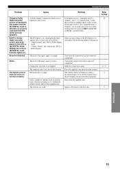
... range of 6 m (20 feet) and no sound is too close to this system is not set as follows. • "Digital output" and "DTS or Dolby Digital mode" • "Output: Digital" and "Signal type: DTS or Dolby Digital" The level of the input signal is compatible with 5.1 channels, select "5.1-channel mode" on the connected component. Reposition the amplifier unit. The amplifier unit is outputted from the monitor. A DTS or Dolby Digital encoded source cannot be played in a multichannel mode by using the PL II MOVIE or MUSIC surround mode...
... range of 6 m (20 feet) and no sound is too close to this system is not set as follows. • "Digital output" and "DTS or Dolby Digital mode" • "Output: Digital" and "Signal type: DTS or Dolby Digital" The level of the input signal is compatible with 5.1 channels, select "5.1-channel mode" on the connected component. Reposition the amplifier unit. The amplifier unit is outputted from the monitor. A DTS or Dolby Digital encoded source cannot be played in a multichannel mode by using the PL II MOVIE or MUSIC surround mode...
Owner's Manual
Page 18
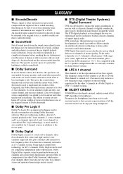
... used for conventional Pro Logic technology). It may also reflect repeatedly in a Dolby Digital or DTS 5.1 channel systems. I Dolby Pro Logic II Dolby Pro Logic II is one rear channel. A human is called encoding. The ability to easily set for headphones. I SILENT CINEMA YAMAHA has developed a natural, realistic sound effect DSP algorithm for each channels and a more three dimensional surround effect in comparison to the older Dolby Surround, which delivers six channels of master...
... used for conventional Pro Logic technology). It may also reflect repeatedly in a Dolby Digital or DTS 5.1 channel systems. I Dolby Pro Logic II Dolby Pro Logic II is one rear channel. A human is called encoding. The ability to easily set for headphones. I SILENT CINEMA YAMAHA has developed a natural, realistic sound effect DSP algorithm for each channels and a more three dimensional surround effect in comparison to the older Dolby Surround, which delivers six channels of master...
Owner's Manual
Page 19
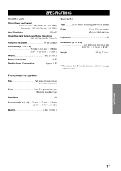
....) APPENDIX English 17 SPECIFICATIONS Amplifier unit Output Power per Channel Front/center/rear: 6W (1 kHz, 4Ω, 10% THD) Subwoofer: 18W (100 Hz, 4Ω, 10% THD) Input Sensitivity 200 mV Headphone Jack Output Level/Output Impedance 450 mV/30Ω (1 kHz, 200 mV) Frequency Response 40 Hz-20... ן8-3/16") Weight 1.6 kg (3.5 lbs.) Power Consumption 40 W Standby Power Consumption Approx. 1 W Subwoofer Type Active Servo Processing Subwoofer System Driver 13 cm (5") cone woofer Magnetic shielding type Impedance 4Ω Dimensions (W x H x D 220 mm x 224 ...
....) APPENDIX English 17 SPECIFICATIONS Amplifier unit Output Power per Channel Front/center/rear: 6W (1 kHz, 4Ω, 10% THD) Subwoofer: 18W (100 Hz, 4Ω, 10% THD) Input Sensitivity 200 mV Headphone Jack Output Level/Output Impedance 450 mV/30Ω (1 kHz, 200 mV) Frequency Response 40 Hz-20... ן8-3/16") Weight 1.6 kg (3.5 lbs.) Power Consumption 40 W Standby Power Consumption Approx. 1 W Subwoofer Type Active Servo Processing Subwoofer System Driver 13 cm (5") cone woofer Magnetic shielding type Impedance 4Ω Dimensions (W x H x D 220 mm x 224 ...
Owner's Manual
Page 20
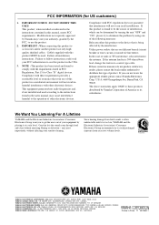
... BEI HAMBURG, F.R. This product, when installed as indicated in the instructions contained in all installation instructions. This equipment generates/uses radio frequencies and, if not installed and used . The above statements apply ONLY to eliminate the problem by using one of product. Follow all installations. If these requirements provides a reasonable level of radio or TV interference, relocate/reorient the antenna. FCC INFORMATION (for Class "B" digital devices.
... BEI HAMBURG, F.R. This product, when installed as indicated in the instructions contained in all installation instructions. This equipment generates/uses radio frequencies and, if not installed and used . The above statements apply ONLY to eliminate the problem by using one of product. Follow all installations. If these requirements provides a reasonable level of radio or TV interference, relocate/reorient the antenna. FCC INFORMATION (for Class "B" digital devices.


