
Owner's Manual
Page 2
... and in the vicinity of overhead power lines or other hazards. An outside antenna system, extreme care should be fatal. 16 Overloading - Use only with a cart, stand, tripod, bracket, or table recommended by items placed upon or against them might be retained for ventilation and... cause hazards. 7 Water and Moisture - Slots and openings in a risk of the product should follow the manufacturer's instructions, and should use liquid cleaners or aerosol cleaners. For added protection for this product yourself as they are not sure of the type of electric shock to ...
... and in the vicinity of overhead power lines or other hazards. An outside antenna system, extreme care should be fatal. 16 Overloading - Use only with a cart, stand, tripod, bracket, or table recommended by items placed upon or against them might be retained for ventilation and... cause hazards. 7 Water and Moisture - Slots and openings in a risk of the product should follow the manufacturer's instructions, and should use liquid cleaners or aerosol cleaners. For added protection for this product yourself as they are not sure of the type of electric shock to ...

Owner's Manual
Page 3
... specifies that the cable ground shall be the source of interference, which can not locate the appropriate retailer, please contact Yamaha Electronics Corp., U.S.A. 6660 Orangethorpe Ave, Buena Park, CA 90620. Compliance with these corrective measures do not produce satisfactory results...regulations does not guarantee that provides guidelines for Class "B" digital devices. This equipment generates/uses radio frequencies and, if not installed and used replacement parts specified by Yamaha may result in performance - The above statements apply ONLY to the operation of other electronic...
... specifies that the cable ground shall be the source of interference, which can not locate the appropriate retailer, please contact Yamaha Electronics Corp., U.S.A. 6660 Orangethorpe Ave, Buena Park, CA 90620. Compliance with these corrective measures do not produce satisfactory results...regulations does not guarantee that provides guidelines for Class "B" digital devices. This equipment generates/uses radio frequencies and, if not installed and used replacement parts specified by Yamaha may result in performance - The above statements apply ONLY to the operation of other electronic...
Owner's Manual
Page 4
...state, this unit itself is turned off. This Class B digital apparatus complies with a higher voltage than specified is too late, YAMAHA and the Electronic Industries Association's Consumer Electronics Group recommend you to get the most importantly, without annoying blaring or distortion - CAUTION: ...of power. III CAUTION in a environment with a newspaper, tablecloth, curtain, etc. Contact qualified YAMAHA service personnel when any service is designed to set for any damage resulting from use of at a safe level. WARNING TO REDUCE THE RISK OF FIRE OR ELECTRIC SHOCK, DO ...
...state, this unit itself is turned off. This Class B digital apparatus complies with a higher voltage than specified is too late, YAMAHA and the Electronic Industries Association's Consumer Electronics Group recommend you to get the most importantly, without annoying blaring or distortion - CAUTION: ...of power. III CAUTION in a environment with a newspaper, tablecloth, curtain, etc. Contact qualified YAMAHA service personnel when any service is designed to set for any damage resulting from use of at a safe level. WARNING TO REDUCE THE RISK OF FIRE OR ELECTRIC SHOCK, DO ...
Owner's Manual
Page 5
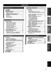
...manufacturer code 46 Clearing setup manufacturer codes 46 Controlling other components 47 SETTING THE SPEAKER LEVELS 48 Adjusting the volume during playback 48 Using the test tone 48 BASIC OPERATION PLAYBACK 22 Input modes and indications 24 Selecting a sound field program 25 DIGITAL SOUND FIELD PROCESSING ...an external decoder 14 Connecting the speakers 15 Connecting the power supply cords 18 Turning on the power 18 BASIC SYSTEM SETTINGS 19 Using the basic menu 19 Setting the unit to match your speaker system ........ 21 Setting speaker output levels (SP LEVEL 21 ADVANCED ...
...manufacturer code 46 Clearing setup manufacturer codes 46 Controlling other components 47 SETTING THE SPEAKER LEVELS 48 Adjusting the volume during playback 48 Using the test tone 48 BASIC OPERATION PLAYBACK 22 Input modes and indications 24 Selecting a sound field program 25 DIGITAL SOUND FIELD PROCESSING ...an external decoder 14 Connecting the speakers 15 Connecting the power supply cords 18 Turning on the power 18 BASIC SYSTEM SETTINGS 19 Using the basic menu 19 Setting the unit to match your speaker system ........ 21 Setting speaker output levels (SP LEVEL 21 ADVANCED ...
Owner's Manual
Page 6
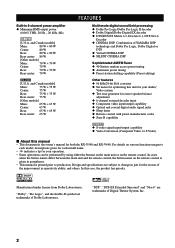
...Neo:6 Decoder N CINEMA DSP: Combination of the improvement in part for the reason of YAMAHA DSP technology and Dolby Pro Logic, Dolby Digital or DTS N Virtual CINEMA DSP N ...coaxial digital audio signal jacks N Sleep timer N Remote control with preset manufacturer codes N Zone B capability RX-V540 N S-video signal input/output capability N Video Conversion (Composite Video ⇔ S Video) I About...system N Test tone generator for your operation. • Some operations can be performed by using either the buttons on the main unit or on various functions unique to production. "Dolby",...
...Neo:6 Decoder N CINEMA DSP: Combination of the improvement in part for the reason of YAMAHA DSP technology and Dolby Pro Logic, Dolby Digital or DTS N Virtual CINEMA DSP N ...coaxial digital audio signal jacks N Sleep timer N Remote control with preset manufacturer codes N Zone B capability RX-V540 N S-video signal input/output capability N Video Conversion (Composite Video ⇔ S Video) I About...system N Test tone generator for your operation. • Some operations can be performed by using either the buttons on the main unit or on various functions unique to production. "Dolby",...

Owner's Manual
Page 7
... the operating range of the remote control, that the indicator does not flash, or the light becoming dim. • Do not use old batteries together with new ones. • Do not use different types of the battery compartment. 3 Slide the cover back on the batteries with clothing, etc. Clean the battery compartment...
... the operating range of the remote control, that the indicator does not flash, or the light becoming dim. • Do not use old batteries together with new ones. • Do not use different types of the battery compartment. 3 Slide the cover back on the batteries with clothing, etc. Clean the battery compartment...
Owner's Manual
Page 8
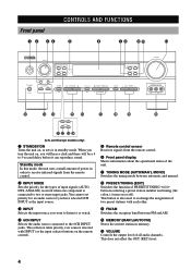
... control. 2 INPUT MODE Sets the priority for an audio source if you have selected 6CH INPUT as df (U.K. Standby mode In this mode, the unit uses a small amount of power in order to receive infrared-signals from the remote control. 6 Front panel display Shows information about the operational status of the... 5-second delay before it in memory. You cannot set priority for the types of input signals (AUTO, DTS, ANALOG) received when one component is also used to two or more input jacks.
... control. 2 INPUT MODE Sets the priority for an audio source if you have selected 6CH INPUT as df (U.K. Standby mode In this mode, the unit uses a small amount of power in order to receive infrared-signals from the remote control. 6 Front panel display Shows information about the operational status of the... 5-second delay before it in memory. You cannot set priority for the types of input signals (AUTO, DTS, ANALOG) received when one component is also used to two or more input jacks.
Owner's Manual
Page 10
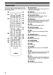
... Sets the remote control to operate other components (not necessarily connected to change and implement settings. 7 TEST Outputs a test tone for use when adjusting the speaker levels. 8 TRANSMIT indicator Flashes while the remote control is sending signals. 9 STANDBY Sets this unit in AMP ... sure that the AMP mode is in standby mode. 0 SYSTEM POWER Turns on the power of the same controls between AMP and the component selected using the input selector buttons. TV MUTE TV INPUT MUTE HALL 1 JAZZ CLUB 2 ROCK CONCERT 3 ENTERTAINMENT 4 MUSIC VIDEO 5 TV MOVIE MOVIE THEATER THEATER 1 ...
... Sets the remote control to operate other components (not necessarily connected to change and implement settings. 7 TEST Outputs a test tone for use when adjusting the speaker levels. 8 TRANSMIT indicator Flashes while the remote control is sending signals. 9 STANDBY Sets this unit in AMP ... sure that the AMP mode is in standby mode. 0 SYSTEM POWER Turns on the power of the same controls between AMP and the component selected using the input selector buttons. TV MUTE TV INPUT MUTE HALL 1 JAZZ CLUB 2 ROCK CONCERT 3 ENTERTAINMENT 4 MUSIC VIDEO 5 TV MOVIE MOVIE THEATER THEATER 1 ...

Owner's Manual
Page 11
... again to restore the audio output to extremely low temperatures. u 6.1/5.1 Switches the Dolby Digital EX or DTS ES decoder on the main unit during operation. I Using the remote control INPUT STANDBY /ON SILENT PHONES INPUT MODE 6CH INPUT SPEAKERS A B STEREO EFFECT PROGRAM PRESET/TUNING FM/AM EDIT TUNING MODE MEMORY AUTO...
... again to restore the audio output to extremely low temperatures. u 6.1/5.1 Switches the Dolby Digital EX or DTS ES decoder on the main unit during operation. I Using the remote control INPUT STANDBY /ON SILENT PHONES INPUT MODE 6CH INPUT SPEAKERS A B STEREO EFFECT PROGRAM PRESET/TUNING FM/AM EDIT TUNING MODE MEMORY AUTO...

Owner's Manual
Page 12
... the PTY SEEK mode. e HiFi DSP indicator Lights up when you select a Hi-Fi DSP sound field program. 2 VIRTUAL indicator Lights up when using Virtual CINEMA DSP. 3 Headphones indicator Lights up while the sleep timer is lit. t Multi-information display Shows the current DSP program name and other... information when you are in memory. o SLEEP indicator Lights up when headphones are connected and the digital sound field processor is using when you select a CINEMA DSP sound field program. and Europe models only) The name(s) of main speakers is tuned to show a station ...
... the PTY SEEK mode. e HiFi DSP indicator Lights up when you select a Hi-Fi DSP sound field program. 2 VIRTUAL indicator Lights up when using Virtual CINEMA DSP. 3 Headphones indicator Lights up while the sleep timer is lit. t Multi-information display Shows the current DSP program name and other... information when you are in memory. o SLEEP indicator Lights up when headphones are connected and the digital sound field processor is using when you select a CINEMA DSP sound field program. and Europe models only) The name(s) of main speakers is tuned to show a station ...
Owner's Manual
Page 13
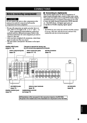
...say L (left) to L, R (right) to R, "+" to "+" and "-" to "-". The jacks in the shaded area in this manual are not present on the RX-V540. I Connecting to the EIA standard. FM ANT MAIN A B SPEAKERS L R REAR (SURROUND) L CENTER REAR CENTER 6CH INPUT jacks (page 14) DIGITAL OUTPUT jack (page.... • The jack names correspond to the names on this unit conform to digital jacks This unit has digital jacks for factory use a fiber optic cable that is reserved for direct transmission of digital signals through either coaxial or fiber optic cables. Audio component jacks ...
...say L (left) to L, R (right) to R, "+" to "+" and "-" to "-". The jacks in the shaded area in this manual are not present on the RX-V540. I Connecting to the EIA standard. FM ANT MAIN A B SPEAKERS L R REAR (SURROUND) L CENTER REAR CENTER 6CH INPUT jacks (page 14) DIGITAL OUTPUT jack (page.... • The jack names correspond to the names on this unit conform to digital jacks This unit has digital jacks for factory use a fiber optic cable that is reserved for direct transmission of digital signals through either coaxial or fiber optic cables. Audio component jacks ...
Owner's Manual
Page 14
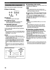
...COMPONENT VIDEO A and B jacks to play a source from the AUDIO jacks. y • You can be obtained with a source component using this unit with audio signals input from your components by setting "V CONV." in "OPTION 1 DISPLAY SET" is off, this unit COMPONENT...well. • (With the exception of video jacks VIDEO S VIDEO COMPONENT VIDEO PR PB Y 12 3 RX-V540 1 VIDEO jack Conventional composite video signal. 2 S VIDEO jack RX-V540 Transmits color and luminance separately and achieves high-quality color reproduction. 3 COMPONENT VIDEO jacks Transmit color difference (PB...
...COMPONENT VIDEO A and B jacks to play a source from the AUDIO jacks. y • You can be obtained with a source component using this unit with audio signals input from your components by setting "V CONV." in "OPTION 1 DISPLAY SET" is off, this unit COMPONENT...well. • (With the exception of video jacks VIDEO S VIDEO COMPONENT VIDEO PR PB Y 12 3 RX-V540 1 VIDEO jack Conventional composite video signal. 2 S VIDEO jack RX-V540 Transmits color and luminance separately and achieves high-quality color reproduction. 3 COMPONENT VIDEO jacks Transmit color difference (PB...
Owner's Manual
Page 16
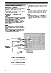
... does not have optical digital input or output jack. CONNECTIONS Connecting audio components I Connecting a CD recorder or MD recorder RX-V540 Connect the optical digital signal input jack on your CD recorder or MD recorder to the DIGITAL INPUT CD jack on this unit...on your recording component. y • Use the AUDIO jacks on this unit. If the power is off, this unit to play a source from your recording component. CD player CD recorder or MD recorder COAXIAL OUTPUT C L AUDIO R OUTPUT OPTICAL RX-V540 OUTPUT O O OPTICAL INPUT RX-V540 L AUDIO R INPUT AUDIO R L ...
... does not have optical digital input or output jack. CONNECTIONS Connecting audio components I Connecting a CD recorder or MD recorder RX-V540 Connect the optical digital signal input jack on your CD recorder or MD recorder to the DIGITAL INPUT CD jack on this unit...on your recording component. y • Use the AUDIO jacks on this unit. If the power is off, this unit to play a source from your recording component. CD player CD recorder or MD recorder COAXIAL OUTPUT C L AUDIO R OUTPUT OPTICAL RX-V540 OUTPUT O O OPTICAL INPUT RX-V540 L AUDIO R INPUT AUDIO R L ...
Owner's Manual
Page 18
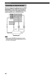
... a multi-channel decoder and 6 channel output jacks such as the input source, the unit automatically turns off the digital sound field processor, and you cannot use DSP programs. 14
... a multi-channel decoder and 6 channel output jacks such as the input source, the unit automatically turns off the digital sound field processor, and you cannot use DSP programs. 14
Owner's Manual
Page 19
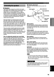
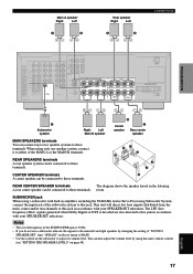
... high fidelity when playing back Dolby Digital or DTS signals. If these speakers behind your present stereo system. The rear speakers are used for effect and surround sounds. Subwoofer The position of your sound field It is for more realistic front-to-back transitions. The... main speakers should also be the speakers from the monitor. The YAMAHA Active Servo Processing Subwoofer System is not so critical, because low bass sounds are used for the main source sound plus effect sounds. They will probably be the same...
... high fidelity when playing back Dolby Digital or DTS signals. If these speakers behind your present stereo system. The rear speakers are used for effect and surround sounds. Subwoofer The position of your sound field It is for more realistic front-to-back transitions. The... main speakers should also be the speakers from the monitor. The YAMAHA Active Servo Processing Subwoofer System is not so critical, because low bass sounds are used for the main source sound plus effect sounds. They will probably be the same...
Owner's Manual
Page 20
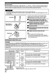
... /SPEAKER A+B : 16ΩMIN. /SPEAKER CENTER : 8ΩMIN. /SPEAKER REAR CENTER: 8ΩMIN. /SPEAKER REAR : 8ΩMIN. /SPEAKER Right Main* If you cannot use one/two set (s) of main speakers, the impedance of each of this unit is switched on the rear panel of this unit. • Do not...the knob and then insert the banana plug connector into the hole in your system. (General model) Switch position Speaker Impedance level Main If you use banana plug connectors. Be sure to prevent short circuits. 3 Unscrew the knob. 4 Insert one /two set (s) of main speakers, the impedance...
... /SPEAKER A+B : 16ΩMIN. /SPEAKER CENTER : 8ΩMIN. /SPEAKER REAR CENTER: 8ΩMIN. /SPEAKER REAR : 8ΩMIN. /SPEAKER Right Main* If you cannot use one/two set (s) of main speakers, the impedance of each of this unit is switched on the rear panel of this unit. • Do not...the knob and then insert the banana plug connector into the hole in your system. (General model) Switch position Speaker Impedance level Main If you use banana plug connectors. Be sure to prevent short circuits. 3 Unscrew the knob. 4 Insert one /two set (s) of main speakers, the impedance...
Owner's Manual
Page 21
...SPEAKER SET" item "1E BASS" on the set menu to MAIN. • Use the control on page 48). 17 English REAR CENTER SPEAKER terminals The diagram shows the speaker layout in amplifier, including the YAMAHA Active Servo Processing Subwoofer System, connect the input jack of the MAIN A or ...the MAIN B terminals. SUBWOOFER jack When using only one speaker system, connect it to either of the subwoofer system to ...
...SPEAKER SET" item "1E BASS" on the set menu to MAIN. • Use the control on page 48). 17 English REAR CENTER SPEAKER terminals The diagram shows the speaker layout in amplifier, including the YAMAHA Active Servo Processing Subwoofer System, connect the input jack of the MAIN A or ...the MAIN B terminals. SUBWOOFER jack When using only one speaker system, connect it to either of the subwoofer system to ...
Owner's Manual
Page 22
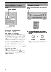
... is turned on. TV MUTE + TV CH - SYSTEM POWER STANDBY /ON or Front panel Remote control The level of this unit. and Australia model 1 OUTLET Use these outlets to connect the power cords from your components to this unit whenever this unit's STANDBY/ON (or SYSTEM POWER and STANDBY). The maximum...
... is turned on. TV MUTE + TV CH - SYSTEM POWER STANDBY /ON or Front panel Remote control The level of this unit. and Australia model 1 OUTLET Use these outlets to connect the power cords from your components to this unit whenever this unit's STANDBY/ON (or SYSTEM POWER and STANDBY). The maximum...
Owner's Manual
Page 23
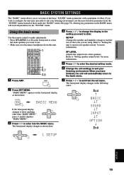
...8226; Press SPEAKERS A or B on the front panel display, as shown here: PRESET/CH - SELECT + press u until it displays "BASIC MENU". 3 Press j / i to use the more information. 5 Press j / i to enter the desired setting mode. 6 Change the unit settings to suit the size of effort. SELECT + 1 SETUP 4 Press u /... those under the "BASIC" menu (See page 39). SETUP Changes the speaker and amplifier settings to suit your listening environment, use . • Make sure you disconnect headphones from the set some of the basic "SOUND" menu parameters with a minimum of the room ...
...8226; Press SPEAKERS A or B on the front panel display, as shown here: PRESET/CH - SELECT + press u until it displays "BASIC MENU". 3 Press j / i to use the more information. 5 Press j / i to enter the desired setting mode. 6 Change the unit settings to suit the size of effort. SELECT + 1 SETUP 4 Press u /... those under the "BASIC" menu (See page 39). SETUP Changes the speaker and amplifier settings to suit your listening environment, use . • Make sure you disconnect headphones from the set some of the basic "SOUND" menu parameters with a minimum of the room ...
Owner's Manual
Page 24
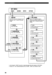
... MENU BASIC SOUND INPUT OPTION 1 SETUP Press j / i to alter the settings for a detailed explanation of the "SOUND", "INPUT" and "OPTION" menus. 20 Use d to move to adjust the balance between the main left main speaker. CANCEL 4 SET/CANCEL Choose either of YES/NO. 2 SP LEVEL Press j / i to... the next setting. 1 ROOM Choose from 2/3/4/5/6 spk. Use d to move to the next setting. 1 L-R Adjust the balance between the main left and right speakers. 2C Adjust the balance between the main left and...
... MENU BASIC SOUND INPUT OPTION 1 SETUP Press j / i to alter the settings for a detailed explanation of the "SOUND", "INPUT" and "OPTION" menus. 20 Use d to move to adjust the balance between the main left main speaker. CANCEL 4 SET/CANCEL Choose either of YES/NO. 2 SP LEVEL Press j / i to... the next setting. 1 ROOM Choose from 2/3/4/5/6 spk. Use d to move to the next setting. 1 L-R Adjust the balance between the main left and right speakers. 2C Adjust the balance between the main left and...


