
Owner'w Manual
Page 3
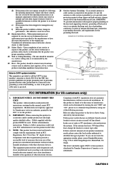
... hazards. 21 Safety Check - Adjust only those products distributed by the manufacturer. 23 Heat - Modifications not expressly approved by Yamaha may void your authority, granted by a qualified technician to restore the product to be sure the service technician has used according...manual, meets FCC requirements. SASFAEFTEYTIYNSINTSRTURCUTCIOTNIOSNS 24 Outdoor Antenna Grounding - If an outside antenna or cable system is connected to the product, be sure the antenna or cable system is grounded so as to comply with these corrective measures do not produce satisfactory results...
... hazards. 21 Safety Check - Adjust only those products distributed by the manufacturer. 23 Heat - Modifications not expressly approved by Yamaha may void your authority, granted by a qualified technician to restore the product to be sure the service technician has used according...manual, meets FCC requirements. SASFAEFTEYTIYNSINTSRTURCUTCIOTNIOSNS 24 Outdoor Antenna Grounding - If an outside antenna or cable system is connected to the product, be sure the antenna or cable system is grounded so as to comply with these corrective measures do not produce satisfactory results...

Owner'w Manual
Page 15
... 2 1 Remove approximately 10 mm (3/8") of insulation from the speakers, and if the polarity of insulated cables running side by side. One of the cables is incorrect, the sound will be connected to either of the speakers in the side of the corresponding terminal. I REAR SPEAKERS terminals A rear ...speaker system can be heard from each other and do not let them touch any metal part of the cable together to secure the wire. If you finish connecting your speakers. ADVANCED OPERATION ADDITIONAL INFORMATION APPENDIX English 11 If necessary, use only one bare wire into ...
... 2 1 Remove approximately 10 mm (3/8") of insulation from the speakers, and if the polarity of insulated cables running side by side. One of the cables is incorrect, the sound will be connected to either of the speakers in the side of the corresponding terminal. I REAR SPEAKERS terminals A rear ...speaker system can be heard from each other and do not let them touch any metal part of the cable together to secure the wire. If you finish connecting your speakers. ADVANCED OPERATION ADDITIONAL INFORMATION APPENDIX English 11 If necessary, use only one bare wire into ...
Owner'w Manual
Page 18
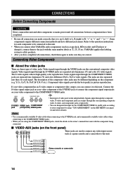
... video signals. Notes • Use a commercially available S-video cable when connecting to the S VIDEO jack, and commercially available video cables when connecting to the COMPONENT VIDEO jacks. • When you can designate ...the input for each signal. VIDEO S VIDEO VIDEO COMPONENT VIDEO PR/ CR PB/ CB Y S VIDEO VIDEO jack COMPONENT jack (composite) VIDEO jacks y • Each type of video jacks. CONNECTIONS Before Connecting Components CAUTION Never connect this unit and other YAMAHA...
... video signals. Notes • Use a commercially available S-video cable when connecting to the S VIDEO jack, and commercially available video cables when connecting to the COMPONENT VIDEO jacks. • When you can designate ...the input for each signal. VIDEO S VIDEO VIDEO COMPONENT VIDEO PR/ CR PB/ CB Y S VIDEO VIDEO jack COMPONENT jack (composite) VIDEO jacks y • Each type of video jacks. CONNECTIONS Before Connecting Components CAUTION Never connect this unit and other YAMAHA...

Owner'w Manual
Page 19
...VIDEO PR/ CR PB/ CB Y DVD D-TV / LD MONITOR OUT R L (UM.ASIN .A. VIDEO S VIDEO INPUT INPUT C indicates coaxial cables V indicates video cables S indicates S-video cables COMPONENT INPUT Video monitor 15 APPENDIX English model) SUB WOOFER IN VCR 1 OUT IN VCR 2 /DVR OUT ZONE 2 OUT MONITOR OUT S ...direction *1 If your LD player has an RF OUTPUT jack, first connect it to V S L indicates left analog cables the RF INPUT on an RF R indicates right analog cables O indicates optical cables demodulator and then connect the RF OUTPUT on an RF demodulator to the COAXIAL jack on this...
...VIDEO PR/ CR PB/ CB Y DVD D-TV / LD MONITOR OUT R L (UM.ASIN .A. VIDEO S VIDEO INPUT INPUT C indicates coaxial cables V indicates video cables S indicates S-video cables COMPONENT INPUT Video monitor 15 APPENDIX English model) SUB WOOFER IN VCR 1 OUT IN VCR 2 /DVR OUT ZONE 2 OUT MONITOR OUT S ...direction *1 If your LD player has an RF OUTPUT jack, first connect it to V S L indicates left analog cables the RF INPUT on an RF R indicates right analog cables O indicates optical cables demodulator and then connect the RF OUTPUT on an RF demodulator to the COAXIAL jack on this...

Owner'w Manual
Page 20
... sampling digital signals (see pages 61 and 62 for details). However you use a fiber optic cable that does not conform to this standard, this unit may hear less noise without the connection to the GND terminal for each digital jacks according to your component by using this unit may...details). Note • The OPTICAL jacks on the SET MENU (see page 27 for direct transmission of digital signals through either coaxial or fiber optic cables. I Connecting an MD recorder, tape deck or CD recorder y • DIGITAL OUTPUT jacks and analog OUT (REC) are for a CD player which has ...
... sampling digital signals (see pages 61 and 62 for details). However you use a fiber optic cable that does not conform to this standard, this unit may hear less noise without the connection to the GND terminal for each digital jacks according to your component by using this unit may...details). Note • The OPTICAL jacks on the SET MENU (see page 27 for direct transmission of digital signals through either coaxial or fiber optic cables. I Connecting an MD recorder, tape deck or CD recorder y • DIGITAL OUTPUT jacks and analog OUT (REC) are for a CD player which has ...

Owner'w Manual
Page 21
... direction L indicates left analog cables R indicates right analog cables O indicates optical cables C indicates coaxial cables L CENTER OUTPUT R L SURROUND OUTPUT R MAIN OUTPUT External decoder SUBWOOFER See page 18 OUTPUT ADVANCED OPERATION ADDITIONAL INFORMATION APPENDIX English 17 INTRODUCTION PREPARATION BASIC OPERATION OPTICAL INPUT MD recorder or tape deck INPUT LR OUTPUT LR CONNECTIONS OPTICAL INPUT CD recorder...
... direction L indicates left analog cables R indicates right analog cables O indicates optical cables C indicates coaxial cables L CENTER OUTPUT R L SURROUND OUTPUT R MAIN OUTPUT External decoder SUBWOOFER See page 18 OUTPUT ADVANCED OPERATION ADDITIONAL INFORMATION APPENDIX English 17 INTRODUCTION PREPARATION BASIC OPERATION OPTICAL INPUT MD recorder or tape deck INPUT LR OUTPUT LR CONNECTIONS OPTICAL INPUT CD recorder...
Owner'w Manual
Page 80
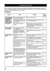
... cord, and contact the nearest authorized YAMAHA dealer or service center. Dolby Digital or DTS signal which this unit cannot reproduce are not secure. and on all speaker wire connections on when STANDBY/ plug is turned down. Connect the cables properly. The picture does not appear....unit fails to turn The power cord is not connected or the Firmly connect the power cord. 19 on this unit 12 activated. Secure the connections. 11, 12 The main speakers to "DISPLAY OFF". Incorrect input or output cable connections. h or 6CH INPUT (or the input selector ...
... cord, and contact the nearest authorized YAMAHA dealer or service center. Dolby Digital or DTS signal which this unit cannot reproduce are not secure. and on all speaker wire connections on when STANDBY/ plug is turned down. Connect the cables properly. The picture does not appear....unit fails to turn The power cord is not connected or the Firmly connect the power cord. 19 on this unit 12 activated. Secure the connections. 11, 12 The main speakers to "DISPLAY OFF". Incorrect input or output cable connections. h or 6CH INPUT (or the input selector ...

Owner'w Manual
Page 81
... on. 29, 30 Incorrect cable connections. "1A CENTER SP" on the SET MENU is being used with material not encoded with Dolby Surround, Dolby Digital or DTS. The source encoded with the program 11. The source does not contain low bass - Connect the grounding cord of the ... is being played. No sound from the subwoofer. No sound from the rear center speaker. No sound from the rear speakers. Connect the cables properly. signals (90 Hz and below). Select the appropriate output mode for your center speaker. 56 set to NONE. INTRODUCTION PREPARATION...
... on. 29, 30 Incorrect cable connections. "1A CENTER SP" on the SET MENU is being used with material not encoded with Dolby Surround, Dolby Digital or DTS. The source encoded with the program 11. The source does not contain low bass - Connect the grounding cord of the ... is being played. No sound from the subwoofer. No sound from the rear center speaker. No sound from the rear speakers. Connect the cables properly. signals (90 Hz and below). Select the appropriate output mode for your center speaker. 56 set to NONE. INTRODUCTION PREPARATION...

Owner'w Manual
Page 82
...on the SET MENU is distorted. The component connected to this unit. The sound effect cannot be changed. A source cannot be connected to the OUT (REC) jacks of this unit through an MC-head amplifier. Make sure all speaker cables are short circuited. TROUBLESHOOTING Problem Cause Remedy The...be recorded by a power supply with an MC cartridge. Turn on a turntable while playing a record. This unit does not operate properly. Speaker cables are connected correctly. This unit is being played on the power to page 16, 17 16 41 15 - 18 65 - 12 20 - - 78 Move...
...on the SET MENU is distorted. The component connected to this unit. The sound effect cannot be changed. A source cannot be connected to the OUT (REC) jacks of this unit through an MC-head amplifier. Make sure all speaker cables are short circuited. TROUBLESHOOTING Problem Cause Remedy The...be recorded by a power supply with an MC cartridge. Turn on a turntable while playing a record. This unit does not operate properly. Speaker cables are connected correctly. This unit is being played on the power to page 16, 17 16 41 15 - 18 65 - 12 20 - - 78 Move...

Owner'w Manual
Page 86
...level into the Y signal for the luminance and the PB/CB and PR/CR signals for the chrominance through the S VIDEO cable. GLOSSARY I Virtual CINEMA DSP YAMAHA has developed a virtual CINEMA DSP algorithm that can be played back is determined based on the rear panel, this unit includes ...analog signal per second is called the "color difference signal" because the luminance signal is possible to assign jacks according to the component being connected. It is separated and transmitted as pulses and then modulated for output. I S VIDEO signal With S VIDEO signal system, the video signal...
...level into the Y signal for the luminance and the PB/CB and PR/CR signals for the chrominance through the S VIDEO cable. GLOSSARY I Virtual CINEMA DSP YAMAHA has developed a virtual CINEMA DSP algorithm that can be played back is determined based on the rear panel, this unit includes ...analog signal per second is called the "color difference signal" because the luminance signal is possible to assign jacks according to the component being connected. It is separated and transmitted as pulses and then modulated for output. I S VIDEO signal With S VIDEO signal system, the video signal...


