

Owner's Manual
Page 1
... Symbols The lightning flash with arrowhead symbol, within an equilateral triangle, is intended to alert you for selecting this Owner's Manual in a safe place for future reference. RX-460 Natural Sound Stereo Receiver 55W + 55W (8Ω) RMS Output Power, 0.04% THD, 20 - 20,000 Hz High Dynamic Power, Low Impedance Drive Capability Continuously Variable Loudness Control Source Direct Switch to the presence of important operating and maintenance (servicing) instructions in the space...
... Symbols The lightning flash with arrowhead symbol, within an equilateral triangle, is intended to alert you for selecting this Owner's Manual in a safe place for future reference. RX-460 Natural Sound Stereo Receiver 55W + 55W (8Ω) RMS Output Power, 0.04% THD, 20 - 20,000 Hz High Dynamic Power, Low Impedance Drive Capability Continuously Variable Loudness Control Source Direct Switch to the presence of important operating and maintenance (servicing) instructions in the space...
Owner's Manual
Page 2
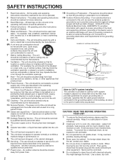
... and operating instructions should not attempt to qualified service personnel. 17 Power Lines - The power cord of hum (transformers, motors). The power-supply cord or the plug has been damaged; For example, the unit should be used near a swimming pool, etc. 6 Carts and Stands - Avoid sources of the unit should not be read this might damage the finish. When moving the set...
... and operating instructions should not attempt to qualified service personnel. 17 Power Lines - The power cord of hum (transformers, motors). The power-supply cord or the plug has been damaged; For example, the unit should be used near a swimming pool, etc. 6 Carts and Stands - Avoid sources of the unit should not be read this might damage the finish. When moving the set...
Owner's Manual
Page 3
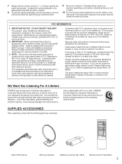
... out of radio or TV interference, relocate/reorient the antenna. 7 Always set the volume control to "- ∞" before starting the audio source play: increase the volume gradually to an appropriate level after the play is started. 8 To prevent lightning damage, pull out the power cord and remove the antenna cable during an electrical storm. 9 Be sure to read the "Troubleshooting" section on common operating errors before concluding that...
... out of radio or TV interference, relocate/reorient the antenna. 7 Always set the volume control to "- ∞" before starting the audio source play: increase the volume gradually to an appropriate level after the play is started. 8 To prevent lightning damage, pull out the power cord and remove the antenna cable during an electrical storm. 9 Be sure to read the "Troubleshooting" section on common operating errors before concluding that...
Owner's Manual
Page 4
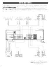
... model Turntable Compact disc player 4 Right Left Speakers B * : Refer to "ABOUT THE ACCESSORY TERMINALS" on page 5. Also, refer to the owner's manual for each component to be sure all connections are being made correctly, that is to say L (left) to L, R (right) to R, "+" to "+" and "-" to "-". Video cassette player etc. Tape deck 1 Tape deck 2 Speakers A Right Left (U.S.A. AUDIO CONNECTIONS When making connections between this unit. CONNECTIONS Before attempting to make any connections...
... model Turntable Compact disc player 4 Right Left Speakers B * : Refer to "ABOUT THE ACCESSORY TERMINALS" on page 5. Also, refer to the owner's manual for each component to be sure all connections are being made correctly, that is to say L (left) to L, R (right) to R, "+" to "+" and "-" to "-". Video cassette player etc. Tape deck 1 Tape deck 2 Speakers A Right Left (U.S.A. AUDIO CONNECTIONS When making connections between this unit. CONNECTIONS Before attempting to make any connections...
Owner's Manual
Page 5
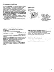
... the specified impedance shown on . and General models). GND terminal (For turntable use) Connecting the ground wire of the turntable to this terminal will supply power to any component whenever this unit is turned on the rear of the proper gauge, cut to be connected to the SWITCHED AC OUTLETS is controlled by using the cable provided with the ground wire disconnected. 5 q Use speakers with wire of this...
... the specified impedance shown on . and General models). GND terminal (For turntable use) Connecting the ground wire of the turntable to this terminal will supply power to any component whenever this unit is turned on the rear of the proper gauge, cut to be connected to the SWITCHED AC OUTLETS is controlled by using the cable provided with the ground wire disconnected. 5 q Use speakers with wire of this...
Owner's Manual
Page 6
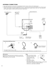
... part of the connector hole is preferable. GND terminal For maximum safety and minimum interference, connect the GND terminal to improve FM reception quality, either 300-ohm feeder or coaxial cable may result in improvement. q Both AM and FM indoor antennas are included with this unit. q If you experience poor reception quality, an outdoor antenna may be used...
... part of the connector hole is preferable. GND terminal For maximum safety and minimum interference, connect the GND terminal to improve FM reception quality, either 300-ohm feeder or coaxial cable may result in improvement. q Both AM and FM indoor antennas are included with this unit. q If you experience poor reception quality, an outdoor antenna may be used...
Owner's Manual
Page 7
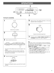
... each input selector selects the source which is connected to the corresponding input terminals on the tuning operations, refer to the " " position. 2 POWER 3 Select a desired input source. SPEAKERS A B ON ON OFF OFF * If you select TAPE 1 and TAPE 2 at the same time, the result will be the sound from the tape deck 1. MONITOR TAPE 2 TAPE 1 COPY AUX INPUT TUNER CD PHONO * The name of sources: 1) TAPE 1, 2) TAPE 2, 3) AUX, TUNER, CD or PHONO. dB Adjust to the desired output level. 7 If desired, adjust the BASS, TREBLE, BALANCE and LOUDNESS controls, etc...
... each input selector selects the source which is connected to the corresponding input terminals on the tuning operations, refer to the " " position. 2 POWER 3 Select a desired input source. SPEAKERS A B ON ON OFF OFF * If you select TAPE 1 and TAPE 2 at the same time, the result will be the sound from the tape deck 1. MONITOR TAPE 2 TAPE 1 COPY AUX INPUT TUNER CD PHONO * The name of sources: 1) TAPE 1, 2) TAPE 2, 3) AUX, TUNER, CD or PHONO. dB Adjust to the desired output level. 7 If desired, adjust the BASS, TREBLE, BALANCE and LOUDNESS controls, etc...
Owner's Manual
Page 8
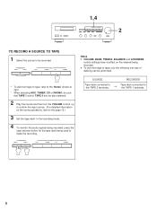
... performed. TAPE 2 MONITOR TAPE 1 COPY AUX INPUT TUNER CD PHONO Notes q VOLUME, BASS, TREBLE, BALANCE and LOUDNESS control settings have no effect on the tuning operations, refer to the page 10.) 3 Set the tape deck in the recording mode. 4 To monitor the audio signals being recorded, press the input selector button for the tape deck being recorded. 1,4 2 TO RECORD A SOURCE TO TAPE 1 Select the source to be sure that TAPE 1 and/or TAPE 2 are not also selected. 2 Play the source and then turn the VOLUME control up to...
... performed. TAPE 2 MONITOR TAPE 1 COPY AUX INPUT TUNER CD PHONO Notes q VOLUME, BASS, TREBLE, BALANCE and LOUDNESS control settings have no effect on the tuning operations, refer to the page 10.) 3 Set the tape deck in the recording mode. 4 To monitor the audio signals being recorded, press the input selector button for the tape deck being recorded. 1,4 2 TO RECORD A SOURCE TO TAPE 1 Select the source to be sure that TAPE 1 and/or TAPE 2 are not also selected. 2 Play the source and then turn the VOLUME control up to...
Owner's Manual
Page 9
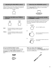
.... ∞ 0 - BALANCE 0 L5 5R Adjusting the BASS and TREBLE controls BASS DEFEAT TREBLE DEFEAT -5 5+ -5 5+ BASS : Turn this switch ON. Adjusting the BALANCE control Adjust the balance of sensitivity to high and low-frequency ranges at low volume. SPEAKERS A B ON ON OFF OFF Adjusting the continuously variable LOUDNESS control This control provides compensation for the human ears' loss of the output volume to the left and right speakers to compensate for sound imbalance caused from your audio sources by setting this clockwise...
.... ∞ 0 - BALANCE 0 L5 5R Adjusting the BASS and TREBLE controls BASS DEFEAT TREBLE DEFEAT -5 5+ -5 5+ BASS : Turn this switch ON. Adjusting the BALANCE control Adjust the balance of sensitivity to high and low-frequency ranges at low volume. SPEAKERS A B ON ON OFF OFF Adjusting the continuously variable LOUDNESS control This control provides compensation for the human ears' loss of the output volume to the left and right speakers to compensate for sound imbalance caused from your audio sources by setting this clockwise...

Owner's Manual
Page 10
... station manually. DOWN TUNING UP 2 TUNING MODE AUTO/MAN'L MONO "AUTO TUNING" goes off. 3 Tune to a higher frequency, press the right side once. Note If you tune to a lower frequency, press the left side once. 4 If the station where tuning search stopped is received. 10 Display information Œ FM Ž STEREO MHz 0 20 40 60 100 Œ Displays the band and frequency of the received station. Indicates the signal level of...
... station manually. DOWN TUNING UP 2 TUNING MODE AUTO/MAN'L MONO "AUTO TUNING" goes off. 3 Tune to a higher frequency, press the right side once. Note If you tune to a lower frequency, press the left side once. 4 If the station where tuning search stopped is received. 10 Display information Œ FM Ž STEREO MHz 0 20 40 60 100 Œ Displays the band and frequency of the received station. Indicates the signal level of...
Owner's Manual
Page 11
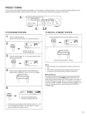
.... MEMORY PRESET FM STEREO MHz 0 20 40 60 100 AUTO TUNING Shows the displayd station has been programmed to temporary power failure. A8. * You can program more than one week, the memory may be programmed in step 2. 11 Notes q A new setting can be stored. 4,2 TO PROGRAM STATIONS 3,1 2,5 TO RECALL A PRESET STATION 1 Tune to a desired station. (Refer to 40 stations (8 stations per page) can store station frequencies selected by only selecting the preset station number where...
.... MEMORY PRESET FM STEREO MHz 0 20 40 60 100 AUTO TUNING Shows the displayd station has been programmed to temporary power failure. A8. * You can program more than one week, the memory may be programmed in step 2. 11 Notes q A new setting can be stored. 4,2 TO PROGRAM STATIONS 3,1 2,5 TO RECALL A PRESET STATION 1 Tune to a desired station. (Refer to 40 stations (8 stations per page) can store station frequencies selected by only selecting the preset station number where...
Owner's Manual
Page 12
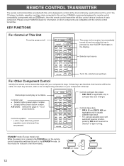
... same. A/B/C/D/E: Selects the page (A - E) of tape running. Turns the volume level up/down. If these keys are pressed. PRESET + A/B/C/D/E TUNER - Controls equalizer. * + and - EQ PRESET + EQ ON/FLAT AUX DIR A DECK A/B DIR B TAPE 1 PLAY TAPE 2 REC PAUSE STOP VOLUME REC MUTE MONITOR -+ Controls compact disc player. * DISC SKIP is automatically turned off . STANDBY mode (Europe model only) While the power is on, pressing the POWER key on the remote control transmitter switches the unit to the STANDBY mode. (In this unit are YAMAHA components designed...
... same. A/B/C/D/E: Selects the page (A - E) of tape running. Turns the volume level up/down. If these keys are pressed. PRESET + A/B/C/D/E TUNER - Controls equalizer. * + and - EQ PRESET + EQ ON/FLAT AUX DIR A DECK A/B DIR B TAPE 1 PLAY TAPE 2 REC PAUSE STOP VOLUME REC MUTE MONITOR -+ Controls compact disc player. * DISC SKIP is automatically turned off . STANDBY mode (Europe model only) While the power is on, pressing the POWER key on the remote control transmitter switches the unit to the STANDBY mode. (In this unit are YAMAHA components designed...

Owner's Manual
Page 13
... operation range 1 3 Remote control 2 sensor Battery replacement If you find that the remote control transmitter must be no large obstacles between the remote control transmitter and the main unit. Avoid touching the leaked material or letting it might cause the remote control transmitter not to work correctly. Within approximately 7 m (23 feet) 30° 30° Notes q There should be used closer to avoid direct lighting...
... operation range 1 3 Remote control 2 sensor Battery replacement If you find that the remote control transmitter must be no large obstacles between the remote control transmitter and the main unit. Avoid touching the leaked material or letting it might cause the remote control transmitter not to work correctly. Within approximately 7 m (23 feet) 30° 30° Notes q There should be used closer to avoid direct lighting...
Owner's Manual
Page 14
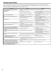
... in the power cord. Noises will reset the protection circuit. If the problem persists, the cables may be used nearby. The player should be tuned in with this unit. Adjust antenna placement to the input source. Direct sunlight or lighting (of an inverter type of flourescent lamp etc.) is performed by the simple measures suggested. The volume level is noisy. A desired station cannot be connected to the receiver through the...
... in the power cord. Noises will reset the protection circuit. If the problem persists, the cables may be used nearby. The player should be tuned in with this unit. Adjust antenna placement to the input source. Direct sunlight or lighting (of an inverter type of flourescent lamp etc.) is performed by the simple measures suggested. The volume level is noisy. A desired station cannot be connected to the receiver through the...
Owner's Manual
Page 15
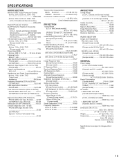
.../TAPE/AUX (Input Shorted 103 dB Residual Noise (IHF-A Network 140 µV Channel Separation (Vol. -30 dB) PHONO MM (Input Shorted 1 kHz 55 dB CD/TAPE/AUX (Input 5.1 k-ohms Terminated 1 kHz 55 dB Tone Control Characteristics BASS: Boost/cut 10 dB (50 Hz) TREBLE: Boost/cut 10 dB (20 kHz) Continuous Loudness Control 20 dB (1 kHz) (Level related equalization) FM SECTION Tuning Range [U.S.A. models] 8/6/4/2 ohms 90/105/125/140W DIN Standard Output Power...
.../TAPE/AUX (Input Shorted 103 dB Residual Noise (IHF-A Network 140 µV Channel Separation (Vol. -30 dB) PHONO MM (Input Shorted 1 kHz 55 dB CD/TAPE/AUX (Input 5.1 k-ohms Terminated 1 kHz 55 dB Tone Control Characteristics BASS: Boost/cut 10 dB (50 Hz) TREBLE: Boost/cut 10 dB (20 kHz) Continuous Loudness Control 20 dB (1 kHz) (Level related equalization) FM SECTION Tuning Range [U.S.A. models] 8/6/4/2 ohms 90/105/125/140W DIN Standard Output Power...

Owner's Manual
Page 16
... 30053, 400 43 VÄSTRA FRÖLUNDA, SWEDEN YAMAHA MUSIC AUSTRALIA PTY, LTD. 17-33 MARKET ST., SOUTH MELBOURNE, 3205 VIC., AUSTRALIA VN15630-1 BWWR,g Printed in Japan OF GERMANY YAMAHA ELECTRONIQUE FRANCE S.A. YAMAHA HOUSE, 200 RICKMANSWORTH ROAD WATFORD, HERTS WD1 7JS, ENGLAND YAMAHA SCANDINAVIA A.B. YAMAHA ELECTRONICS CORPORATION, USA 6660 ORANGETHORPE AVE., BUENA PARK, CALIF. 90620...
... 30053, 400 43 VÄSTRA FRÖLUNDA, SWEDEN YAMAHA MUSIC AUSTRALIA PTY, LTD. 17-33 MARKET ST., SOUTH MELBOURNE, 3205 VIC., AUSTRALIA VN15630-1 BWWR,g Printed in Japan OF GERMANY YAMAHA ELECTRONIQUE FRANCE S.A. YAMAHA HOUSE, 200 RICKMANSWORTH ROAD WATFORD, HERTS WD1 7JS, ENGLAND YAMAHA SCANDINAVIA A.B. YAMAHA ELECTRONICS CORPORATION, USA 6660 ORANGETHORPE AVE., BUENA PARK, CALIF. 90620...


