
Owner's Manual
Page 9
... General Specifications 346 Input/output characteristics 348 Electrical characteristics 352 Other Functions 354 Pin Assignment 355 Dimensions 356 MIDI Implementation Chart 357 Index 358 PM5D/PM5D-RH Block Diagram End of Manual PM5D Level Diagram End of Manual PM5D-RH Level Diagram End of Manual • The illustrations and screen displays as shown in this... from the ones on your device. • The company names and product names in this Owner's Manual are the trademarks or registered trademarks of Contents 9 PM5D/PM5D-RH Owner's Manual Table of their respective companies.
... General Specifications 346 Input/output characteristics 348 Electrical characteristics 352 Other Functions 354 Pin Assignment 355 Dimensions 356 MIDI Implementation Chart 357 Index 358 PM5D/PM5D-RH Block Diagram End of Manual PM5D Level Diagram End of Manual PM5D-RH Level Diagram End of Manual • The illustrations and screen displays as shown in this... from the ones on your device. • The company names and product names in this Owner's Manual are the trademarks or registered trademarks of Contents 9 PM5D/PM5D-RH Owner's Manual Table of their respective companies.
Owner's Manual
Page 178
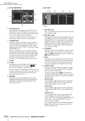
...GPI IN voltage changes. The setting of the GPI screen's FADER START field is respectively indicated by a yellow in the X-axis (horizontal) and Y-axis (vertical) dimensions of the graph. MIDI REMOTE function ❏ GPI IN MONITOR 8 6 9 7 J F GPI IN monitor The voltage from the GPI IN port selected by ...the XAXIS field (8) and Y-AXIS field (9) is linked with the GPI-related settings of the FADER START screen (➥ p.179). 178 PM5D/PM5D-RH Owner's Manual Reference section the range will be temporarily cleared; If you are the numbers of the GPI OUT ports for the corresponding port...
...GPI IN voltage changes. The setting of the GPI screen's FADER START field is respectively indicated by a yellow in the X-axis (horizontal) and Y-axis (vertical) dimensions of the graph. MIDI REMOTE function ❏ GPI IN MONITOR 8 6 9 7 J F GPI IN monitor The voltage from the GPI IN port selected by ...the XAXIS field (8) and Y-AXIS field (9) is linked with the GPI-related settings of the FADER START screen (➥ p.179). 178 PM5D/PM5D-RH Owner's Manual Reference section the range will be temporarily cleared; If you are the numbers of the GPI OUT ports for the corresponding port...
Owner's Manual
Page 346
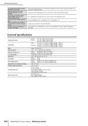
... Cable Studio Manager CD-ROM Studio Manager Installation Guide mini YGDAI cards Power Supply PW800W Power Supply Link Cable PSL120 346 PM5D/PM5D-RH Owner's Manual Reference section Even when channels are too dark / too bright ❍ In the UTILITY function PREFERENCE.... (➥ p.188) General Specifications Sampling Frequency Signal Delay Fader Fader Resolution Maximum Voltage Gain Crosstalk (@1kHz) Dimensions Net Weight Power Requirements Operation free-air Temperature Range Storage Temperature Range Included Accessories Optional Accessories Internal: External: 44.1 kHz,...
... Cable Studio Manager CD-ROM Studio Manager Installation Guide mini YGDAI cards Power Supply PW800W Power Supply Link Cable PSL120 346 PM5D/PM5D-RH Owner's Manual Reference section Even when channels are too dark / too bright ❍ In the UTILITY function PREFERENCE.... (➥ p.188) General Specifications Sampling Frequency Signal Delay Fader Fader Resolution Maximum Voltage Gain Crosstalk (@1kHz) Dimensions Net Weight Power Requirements Operation free-air Temperature Range Storage Temperature Range Included Accessories Optional Accessories Internal: External: 44.1 kHz,...
Owner's Manual
Page 356
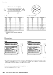
... GPO10 25 GPO11 13 GPO12 * For information on maximum permissible current, refer to change or modify products or specifications at any time without prior notice. Dimensions PM5D 283 271 260 4 3 21 9 8 76 5 15 14 13 12 11 10 20 19 18 17 16 23 22 21 ❏ DC POWER ... 1450 1551 Unit: mm * Specifications and descriptions in every locale, please check with your Yamaha dealer. reserves the right to the page 351. Yamaha Corp. Conforms to Environments: E1, E2, E3 and E4 356 PM5D/PM5D-RH Owner's Manual Reference section Since specifications, equipment or options may not be the same ...
... GPO10 25 GPO11 13 GPO12 * For information on maximum permissible current, refer to change or modify products or specifications at any time without prior notice. Dimensions PM5D 283 271 260 4 3 21 9 8 76 5 15 14 13 12 11 10 20 19 18 17 16 23 22 21 ❏ DC POWER ... 1450 1551 Unit: mm * Specifications and descriptions in every locale, please check with your Yamaha dealer. reserves the right to the page 351. Yamaha Corp. Conforms to Environments: E1, E2, E3 and E4 356 PM5D/PM5D-RH Owner's Manual Reference section Since specifications, equipment or options may not be the same ...
Owner's Manual
Page 358
...DCA 73 DCA CUE indicator 150 DCA GROUP ASSIGN ......... 234, 271 DCA Groups 73, 74 358 PM5D/PM5D-RH Owner's Manual Reference section DELAY 58 Digital input/output connections... 29 Dimensions 356 DIMM indicator 150 DIRECT OUT PATCH.......... 72, 253 DIRECT RECALL 151 DIRECT RECALL ASSIGN.......... 161 ...STIN/FXRTN 262 Numerics 2TR I/O 215 A Accessing a screen 23 AD IN section 35 Add-On Effects 109 Adjusting the input gain (PM5D-RH 148 Adjusting the output gain 148 ADVANCED mode 193, 196 Analog audio connections 27 Analog output connections 28 Appendices 290 Assign ASSIGN MODE...
...DCA 73 DCA CUE indicator 150 DCA GROUP ASSIGN ......... 234, 271 DCA Groups 73, 74 358 PM5D/PM5D-RH Owner's Manual Reference section DELAY 58 Digital input/output connections... 29 Dimensions 356 DIMM indicator 150 DIRECT OUT PATCH.......... 72, 253 DIRECT RECALL 151 DIRECT RECALL ASSIGN.......... 161 ...STIN/FXRTN 262 Numerics 2TR I/O 215 A Accessing a screen 23 AD IN section 35 Add-On Effects 109 Adjusting the input gain (PM5D-RH 148 Adjusting the output gain 148 ADVANCED mode 193, 196 Analog audio connections 27 Analog output connections 28 Appendices 290 Assign ASSIGN MODE...