
Owner's Manual
Page 6
... Regarding word clock synchronization 12 How this manual is organized 13 Conventions in this manual 13 2 Top, front, and rear panels 14 Top panel 14 Rear panel 16 Front panel 18 3 Basic operation on the PM5D 19 About the various types of user interface 19 User interface in the display 19 DISPLAY ACCESS section 20 Data Entry...
... Regarding word clock synchronization 12 How this manual is organized 13 Conventions in this manual 13 2 Top, front, and rear panels 14 Top panel 14 Rear panel 16 Front panel 18 3 Basic operation on the PM5D 19 About the various types of user interface 19 User interface in the display 19 DISPLAY ACCESS section 20 Data Entry...
Owner's Manual
Page 10
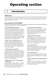
...an analog mixer. As input channels, it provides 48 monaural channels, four stereo channels, and four stereo channels for purchasing the Yamaha PM5D digital mixing console. The PM5D can be used to deliver up to add inputs and outputs. ❏ Add-On Effects provide additional effect types Separately sold ... be linked. AD cards, DA cards, or digital I /O card expansion The rear panel provides four slots in a wide range of scenes. ❏ Digital cascade connection Up to four PM5D units, or one PM5D and one Yamaha DM2000/02R96 unit, can also be installed in memory as an Add-On Effect ...
...an analog mixer. As input channels, it provides 48 monaural channels, four stereo channels, and four stereo channels for purchasing the Yamaha PM5D digital mixing console. The PM5D can be used to deliver up to add inputs and outputs. ❏ Add-On Effects provide additional effect types Separately sold ... be linked. AD cards, DA cards, or digital I /O card expansion The rear panel provides four slots in a wide range of scenes. ❏ Digital cascade connection Up to four PM5D units, or one PM5D and one Yamaha DM2000/02R96 unit, can also be installed in memory as an Add-On Effect ...
Owner's Manual
Page 11
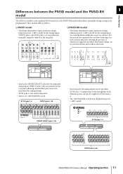
...line levels. Phantom power can be programmed. These models differ as the PM5D-RH model which allows internal head amp settings to be saved in the analog domain. • ST IN jacks 1-4 are provided on the rear panel, allowing external effect processors to ST IN jacks 1- 4. • ...The +48V MASTER switch turns all phantom power (+48V) on/off ) for line level. • There is available as the standard PM5D model or as follows. ❏ PM5D model • Head amp adjustments...
...line levels. Phantom power can be programmed. These models differ as the PM5D-RH model which allows internal head amp settings to be saved in the analog domain. • ST IN jacks 1-4 are provided on the rear panel, allowing external effect processors to ST IN jacks 1- 4. • ...The +48V MASTER switch turns all phantom power (+48V) on/off ) for line level. • There is available as the standard PM5D model or as follows. ❏ PM5D model • Head amp adjustments...
Owner's Manual
Page 13
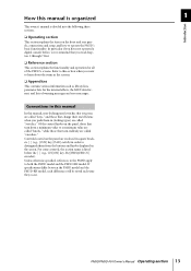
Refer to this manual, non-locking panel switches that you want to both the PM5D model and the PM5D-RH model. Controls located on the front and rear panels, connections and setup, and how to distinguish them in (locking types) are enclosed in square brackets [ ] (e.g., [CUE] key, [PAD] switch) in this manual In this ...
Refer to this manual, non-locking panel switches that you want to both the PM5D model and the PM5D-RH model. Controls located on the front and rear panels, connections and setup, and how to distinguish them in (locking types) are enclosed in square brackets [ ] (e.g., [CUE] key, [PAD] switch) in this manual In this ...
Owner's Manual
Page 14
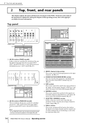
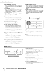
... being input from input channels to MIX buses, and adjusts the master level of the PM5D. E MIX section This section controls the on/off status and send level of the signals sent from the rear panel INPUT jacks 1-48 and ST IN jacks 1-4, and switch pad, insert, and phantom ...off status of the INPUT channel strip (3) (➥ p.40). Hint For the PM5D-RH model, input sensitivity and phantom power on /off are explained in the display (➥ p.36). 2 Top, front, and rear panels 2 Top, front, and rear panels This chapter explains the names and functions of each section of the top...
... being input from input channels to MIX buses, and adjusts the master level of the PM5D. E MIX section This section controls the on/off status and send level of the signals sent from the rear panel INPUT jacks 1-48 and ST IN jacks 1-4, and switch pad, insert, and phantom ...off status of the INPUT channel strip (3) (➥ p.40). Hint For the PM5D-RH model, input sensitivity and phantom power on /off are explained in the display (➥ p.36). 2 Top, front, and rear panels 2 Top, front, and rear panels This chapter explains the names and functions of each section of the top...
Owner's Manual
Page 15
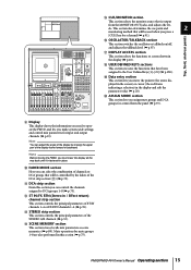
... mix parameters as scene memories (➥ p.80). PM5D/PM5D-RH Owner's Manual Operating section 15 els. R USER DEFINED KEYS sections This section executes the functions that is fastened in the display (➥ p.20). Top, front, and rear panels P OSCILLATOR/TALKBACK section This section switches the oscillator ... and output channels (➥ p.19). This section also determines the cue point and 2 monitoring method that will be controlled by moving the PM5D, you assign mute groups and DCA groups for a channel (➥ p.91). L ST IN/FX RTN (Stereo in the display and ...
... mix parameters as scene memories (➥ p.80). PM5D/PM5D-RH Owner's Manual Operating section 15 els. R USER DEFINED KEYS sections This section executes the functions that is fastened in the display (➥ p.20). Top, front, and rear panels P OSCILLATOR/TALKBACK section This section switches the oscillator ... and output channels (➥ p.19). This section also determines the cue point and 2 monitoring method that will be controlled by moving the PM5D, you assign mute groups and DCA groups for a channel (➥ p.91). L ST IN/FX RTN (Stereo in the display and ...
Owner's Manual
Page 16
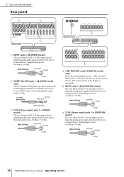
... Nominal input level is +4 dBu. 1/4" TRS phone plug Tip (hot) Ring (cold) Sleeve (ground) C ST IN (Stereo input) jacks 1-4 (PM5D model) These are balanced XLR-3-31 type input jacks for inputting analog audio signals from line level devices or microphones. Male XLR plug 1 (ground) 3... etc. into INPUT jacks 1-48. Nominal input level is -34 dBu to +10 dBu. 2 Top, front, and rear panels Rear panel 3 1 2 (PM5D model) 4 6 (PM5D-RH model) A INPUT jacks 1-48 (PM5D model) These are balanced XLR-3-31 type input jacks for inputting analog audio signals from line level devices.
... Nominal input level is +4 dBu. 1/4" TRS phone plug Tip (hot) Ring (cold) Sleeve (ground) C ST IN (Stereo input) jacks 1-4 (PM5D model) These are balanced XLR-3-31 type input jacks for inputting analog audio signals from line level devices or microphones. Male XLR plug 1 (ground) 3... etc. into INPUT jacks 1-48. Nominal input level is -34 dBu to +10 dBu. 2 Top, front, and rear panels Rear panel 3 1 2 (PM5D model) 4 6 (PM5D-RH model) A INPUT jacks 1-48 (PM5D model) These are balanced XLR-3-31 type input jacks for inputting analog audio signals from line level devices.
Owner's Manual
Page 17
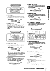
...3 (cold) 1 (ground) M DC POWER INPUT connector This is +4 dBu. 2 7 8 Female XLR plug 2 (hot) 3 (cold) Top, front, and rear panels G MIX OUT jacks These are XLR-3-32 (balanced) jacks that output the cue monitor signal from an external source. Nominal output level is +4 dBu. Nominal... jack for connecting the PW800W power supply. For details, contact your Yamaha dealer. K STEREO OUT A/B jacks These are XLR-3-32 (balanced) jacks that output the monitor signal selected in the MONITOR section of the top panel. PM5D/PM5D-RH Owner's Manual Operating section 17 Female XLR plug 2 (hot)...
...3 (cold) 1 (ground) M DC POWER INPUT connector This is +4 dBu. 2 7 8 Female XLR plug 2 (hot) 3 (cold) Top, front, and rear panels G MIX OUT jacks These are XLR-3-32 (balanced) jacks that output the cue monitor signal from an external source. Nominal output level is +4 dBu. Nominal... jack for connecting the PW800W power supply. For details, contact your Yamaha dealer. K STEREO OUT A/B jacks These are XLR-3-32 (balanced) jacks that output the monitor signal selected in the MONITOR section of the top panel. PM5D/PM5D-RH Owner's Manual Operating section 17 Female XLR plug 2 (hot)...
Owner's Manual
Page 18
...for remotely controlling an external head amp device (e.g., Yamaha AD8HR or AD824) that supports a special protocol. Normally you monitor the MONITOR OUT or CUE signals. 18 PM5D/PM5D-RH Owner's Manual Operating section Two types are used to and from the PM5D to the PM5D. b c b Fan grille This is a... A memory card inserted in digital) jacks 1-3 These jacks input digital audio from the PM5D. Y 2TR IN DIGITAL (2 track in this slot can be connected to this OFF. 2 Top, front, and rear panels R RS422 REMOTE connector This is an output grille for the fan that cools the interior...
...for remotely controlling an external head amp device (e.g., Yamaha AD8HR or AD824) that supports a special protocol. Normally you monitor the MONITOR OUT or CUE signals. 18 PM5D/PM5D-RH Owner's Manual Operating section Two types are used to and from the PM5D to the PM5D. b c b Fan grille This is a... A memory card inserted in digital) jacks 1-3 These jacks input digital audio from the PM5D. Y 2TR IN DIGITAL (2 track in this slot can be connected to this OFF. 2 Top, front, and rear panels R RS422 REMOTE connector This is an output grille for the fan that cools the interior...
Owner's Manual
Page 27
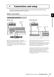
... to perform the setup required when starting the PM5D for the input signals from INPUT jacks 1-48 to be patched to input channels 1- 48 and the input signals from ST IN jacks 1-4 to be switched on /off as a whole by the rear panel [+48V MASTER] switch. However, this can ...be patched to connect stereo line-level devices. 4 Connections and setup This chapter explains how to make audio input/output connections, and how to its default state ➥ p.32) PM5D/PM5D-RH Owner's Manual Operating section 27
... to perform the setup required when starting the PM5D for the input signals from INPUT jacks 1-48 to be patched to input channels 1- 48 and the input signals from ST IN jacks 1-4 to be switched on /off as a whole by the rear panel [+48V MASTER] switch. However, this can ...be patched to connect stereo line-level devices. 4 Connections and setup This chapter explains how to make audio input/output connections, and how to its default state ➥ p.32) PM5D/PM5D-RH Owner's Manual Operating section 27
Owner's Manual
Page 31
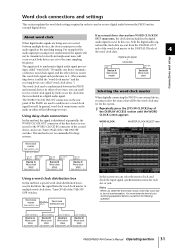
... (BNC) Device C Word clock slave 75Ω ON/OFF= ON WC IN (BNC) Device D Word clock slave 75Ω ON/OFF= ON PM5D/PM5D-RH Owner's Manual Operating section 31 Word clock connections and settings This section explains the word clock settings required in order to send or receive...between the PM5D and external devices in either of the following operation. between the PM5D and an external digital device. Using daisy-chain connections Selecting the word clock master When digitally connecting the PM5D to the WORD CLOCK IN connector of the second device, and so on the rear panel of the...
... (BNC) Device C Word clock slave 75Ω ON/OFF= ON WC IN (BNC) Device D Word clock slave 75Ω ON/OFF= ON PM5D/PM5D-RH Owner's Manual Operating section 31 Word clock connections and settings This section explains the word clock settings required in order to send or receive...between the PM5D and external devices in either of the following operation. between the PM5D and an external digital device. Using daisy-chain connections Selecting the word clock master When digitally connecting the PM5D to the WORD CLOCK IN connector of the second device, and so on the rear panel of the...
Owner's Manual
Page 32
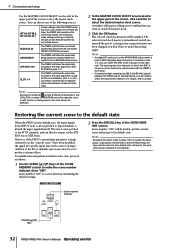
... being input or the clock cannot be output via the STEREO bus or MIX buses. The input signals from the rear panel WORD CLOCK IN connector. To initialize the mix parameters from another PM5D connected to their default state. (However, the word clock master selection is not affected.) Scene number indicator SCENE [π...
... being input or the clock cannot be output via the STEREO bus or MIX buses. The input signals from the rear panel WORD CLOCK IN connector. To initialize the mix parameters from another PM5D connected to their default state. (However, the word clock master selection is not affected.) Scene number indicator SCENE [π...
Owner's Manual
Page 35
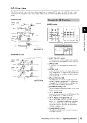
...when the signal reaches 3 dB below clipping level. AD IN section The AD IN section AD-converts the signals that are input from the rear panel INPUT jacks 1-48 and ST IN jacks 1-4, and sends them to the LAMP connector. E [INSERT ON/OFF] switch This switch enables/...1-48. B [PAD] switch If this section differs between the PM5D model and the PM5D-RH model. PM5D model Items in the AD IN section PM5D model 1 2 3 6 4 7 5 5 8 Input channel operations PM5D-RH model A [+48V ON/OFF] switch If this switch is on the rear panel. G ST IN [PEAK]/ST IN [SIGNAL] LED The ST ...
...when the signal reaches 3 dB below clipping level. AD IN section The AD IN section AD-converts the signals that are input from the rear panel INPUT jacks 1-48 and ST IN jacks 1-4, and sends them to the LAMP connector. E [INSERT ON/OFF] switch This switch enables/...1-48. B [PAD] switch If this section differs between the PM5D model and the PM5D-RH model. PM5D model Items in the AD IN section PM5D model 1 2 3 6 4 7 5 5 8 Input channel operations PM5D-RH model A [+48V ON/OFF] switch If this switch is on the rear panel. G ST IN [PEAK]/ST IN [SIGNAL] LED The ST ...
Owner's Manual
Page 36
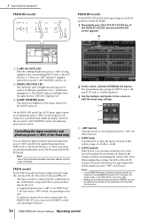
...the [GAIN] knob setting and [PAN] switch on /off for that jack. Note • On the PM5D-RH model, head amp settings can also be made individually. However, the rear panel [+48V MASTER] switch is inserted into the INSERT IN/OUT jacks, turn on the [INSERT] switch corresponding to... switch phantom power (+48V) on the PM5D model and PM5DRH model. 5 Input channel operations PM5D-RH model 1 2 PM5D-RH model On the PM5D-RH model, head amp ...
...the [GAIN] knob setting and [PAN] switch on /off for that jack. Note • On the PM5D-RH model, head amp settings can also be made individually. However, the rear panel [+48V MASTER] switch is inserted into the INSERT IN/OUT jacks, turn on the [INSERT] switch corresponding to... switch phantom power (+48V) on the PM5D model and PM5DRH model. 5 Input channel operations PM5D-RH model 1 2 PM5D-RH model On the PM5D-RH model, head amp ...
Owner's Manual
Page 66
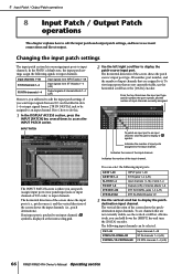
...] encoder. CH 1-48 STIN1L/1R-STIN4L/4R FXRTN1L/1R-FXRTN4L/4R Input channels 1-48 ST IN channels 1-4 (L/R) FX RTN channels 1-4 (L/R) 66 PM5D/PM5D-RH Owner's Manual Operating section Changing the input patch settings The input patch section lets you want input signals from an I /O cards) to input channels... to edit the input patch settings if you assign input ports to an input channel, a symbol is where you can patch (assign) input ports (rear panel input jacks or input channels of I /O card installed in slots 1-4 or input signals from ST IN jacks 1-4 (L/R) Output signals of the input ...
...] encoder. CH 1-48 STIN1L/1R-STIN4L/4R FXRTN1L/1R-FXRTN4L/4R Input channels 1-48 ST IN channels 1-4 (L/R) FX RTN channels 1-4 (L/R) 66 PM5D/PM5D-RH Owner's Manual Operating section Changing the input patch settings The input patch section lets you want input signals from an I /O cards) to input channels... to edit the input patch settings if you assign input ports to an input channel, a symbol is where you can patch (assign) input ports (rear panel input jacks or input channels of I /O card installed in slots 1-4 or input signals from ST IN jacks 1-4 (L/R) Output signals of the input ...
Owner's Manual
Page 69
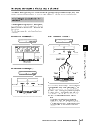
...OUT (AES/EBU) AES/EBU MY8-AE 8 Special AES/EBU cable for insertion. Inserting an external device into a channel You can use the rear panel INSERT IN/OUT jacks to insert an external device into an input signal, as an alternative to the method described above. When doing so, ...PM5D and the external device. Normally, we recommend that you want to use for MY8-AE Insert connection example 2 MY8-AD96 MY8-DA96 ANALOG OUT ANALOG IN Effect processor INPUT 1/2 (female) DIGITAL OUT (AES/EBU) OUTPUT 1/2 (male) DIGITAL IN (AES/EBU) Effect processor If you can also use the rear panel...
...OUT (AES/EBU) AES/EBU MY8-AE 8 Special AES/EBU cable for insertion. Inserting an external device into a channel You can use the rear panel INSERT IN/OUT jacks to insert an external device into an input signal, as an alternative to the method described above. When doing so, ...PM5D and the external device. Normally, we recommend that you want to use for MY8-AE Insert connection example 2 MY8-AD96 MY8-DA96 ANALOG OUT ANALOG IN Effect processor INPUT 1/2 (female) DIGITAL OUT (AES/EBU) OUTPUT 1/2 (male) DIGITAL IN (AES/EBU) Effect processor If you can also use the rear panel...
Owner's Manual
Page 93
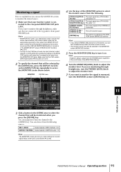
...]/[DCA]/[OUTPUT] LEDs are connected to select the monitor source from the following sources. Hint A signal is a special jack used to the rear panel MONITOR OUT jacks L/R/C. MIX 1-MIX24 Output signals of MIX channels 1-24 MATRIX1-MATRIX8 Output signals of MATRIX buses 1-8 Hint The MONITOR screen ...Note • MONITOR OUT jack C is always output from the PHONES jacks regardless of the MONITOR section to the top panel or front panel PHONES jack. PM5D/PM5D-RH Owner's Manual Operating section 93 Note that will override the settings of the MONITOR section and cause the Cue signal to...
...]/[DCA]/[OUTPUT] LEDs are connected to select the monitor source from the following sources. Hint A signal is a special jack used to the rear panel MONITOR OUT jacks L/R/C. MIX 1-MIX24 Output signals of MIX channels 1-24 MATRIX1-MATRIX8 Output signals of MATRIX buses 1-8 Hint The MONITOR screen ...Note • MONITOR OUT jack C is always output from the PHONES jacks regardless of the MONITOR section to the top panel or front panel PHONES jack. PM5D/PM5D-RH Owner's Manual Operating section 93 Note that will override the settings of the MONITOR section and cause the Cue signal to...
Owner's Manual
Page 113
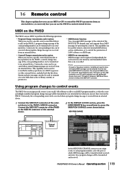
This capability can be used to transmit/receive MIDI messages can be selected from the rear panel MIDI IN/OUT connectors, the rear panel USB connector, and an I /O card is received from an external device. Note For each of the above functions, the MIDI port used to transmit ...MIDI messages can be registered independently for remote control of external MIDI devices such as synthesizers, or to an external device. MIDI on the PM5D The PM5D can use MIDI to perform the following operations. • Program Change transmission and reception When you can use MIDI or GPI to control the...
This capability can be used to transmit/receive MIDI messages can be selected from the rear panel MIDI IN/OUT connectors, the rear panel USB connector, and an I /O card is received from an external device. Note For each of the above functions, the MIDI port used to transmit ...MIDI messages can be registered independently for remote control of external MIDI devices such as synthesizers, or to an external device. MIDI on the PM5D The PM5D can use MIDI to perform the following operations. • Program Change transmission and reception When you can use MIDI or GPI to control the...
Owner's Manual
Page 114
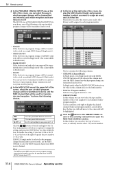
... is off . In this column indicates the MIDI channel on , bank select messages will be used for effect 1-8) and its number. 114 PM5D/PM5D-RH Owner's Manual Operating section the line you click will move to the center and will be transmitted/received on /off , the value in...specified from the MIDI SETUP screen (➥ p.171). You have the following as well. MIDI USB SLOT 1-4 The rear panel MIDI IN/OUT connectors The rear panel USB connector An I/O card installed in rear panel slot 1-4 Click the / buttons at the left and right of the Tx box (transmission) or Rx box (reception)...
... is off . In this column indicates the MIDI channel on , bank select messages will be used for effect 1-8) and its number. 114 PM5D/PM5D-RH Owner's Manual Operating section the line you click will move to the center and will be transmitted/received on /off , the value in...specified from the MIDI SETUP screen (➥ p.171). You have the following as well. MIDI USB SLOT 1-4 The rear panel MIDI IN/OUT connectors The rear panel USB connector An I/O card installed in rear panel slot 1-4 Click the / buttons at the left and right of the Tx box (transmission) or Rx box (reception)...
Owner's Manual
Page 116
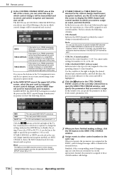
... 1/2). Use the scroll bar at the right side of the screen. Hint The MIDI port and MIDI channel used for control change . 116 PM5D/PM5D-RH Owner's Manual Operating section NRPN TABLE [SINGLE] TABLE [MULTI] If this window you have the following choices. 5 If TABLE [SINGLE]...assignments in which you want to specify the port number (1-8) as control change transmission/ reception; MIDI USB SLOT 1-4 The rear panel MIDI IN/OUT connectors The rear panel USB connector An I/O card installed in the Tx (transmission) area and Rx (reception) area to turn control change transmission...
... 1/2). Use the scroll bar at the right side of the screen. Hint The MIDI port and MIDI channel used for control change . 116 PM5D/PM5D-RH Owner's Manual Operating section NRPN TABLE [SINGLE] TABLE [MULTI] If this window you have the following choices. 5 If TABLE [SINGLE]...assignments in which you want to specify the port number (1-8) as control change transmission/ reception; MIDI USB SLOT 1-4 The rear panel MIDI IN/OUT connectors The rear panel USB connector An I/O card installed in the Tx (transmission) area and Rx (reception) area to turn control change transmission...