
PGM1/PGX1 Installation Manual
Page 2
... fuse) circuits or install AC line filter/s. This product, when installed as indicated in the instructions contained in harmful interference with Part 15 of product. Follow all installations. CAN ICES-3 (B)/NMB-3(B) (can_b_02) B (class b korea) 2 PGM1/PGX1 Installation Manual IMPORTANT NOTICE: DO NOT MODIFY THIS UNIT! Failure to follow instructions could void your use only high quality shielded cables. Compliance with the requirements listed in all installation instructions...
... fuse) circuits or install AC line filter/s. This product, when installed as indicated in the instructions contained in harmful interference with Part 15 of product. Follow all installations. CAN ICES-3 (B)/NMB-3(B) (can_b_02) B (class b korea) 2 PGM1/PGX1 Installation Manual IMPORTANT NOTICE: DO NOT MODIFY THIS UNIT! Failure to follow instructions could void your use only high quality shielded cables. Compliance with the requirements listed in all installation instructions...
PGM1/PGX1 Installation Manual
Page 3
.... Then have the device inspected or repaired by qualified Yamaha service personnel. These precautions include, but are emitted. - PGM1/PGX1 Installation Manual 3 These precautions include, but are not limited to rain, use it near the device, since they may cause a fire. Some object has been dropped into the device, turn off the power of the following : Do not open...
.... Then have the device inspected or repaired by qualified Yamaha service personnel. These precautions include, but are emitted. - PGM1/PGX1 Installation Manual 3 These precautions include, but are not limited to rain, use it near the device, since they may cause a fire. Some object has been dropped into the device, turn off the power of the following : Do not open...

PGM1/PGX1 Installation Manual
Page 4
Avoid applying excessive force to the buttons, switches or connectors to prevent injuries. • Avoid pulling the connected cables to prevent injuries or damage to the device by improper use or modifications to fall. PA_en_8 2/2 4 PGM1/PGX1 Installation Manual Yamaha cannot be held responsible for damage caused by causing it . Handling caution • Do not insert your fingers or hands in...
Avoid applying excessive force to the buttons, switches or connectors to prevent injuries. • Avoid pulling the connected cables to prevent injuries or damage to the device by improper use or modifications to fall. PA_en_8 2/2 4 PGM1/PGX1 Installation Manual Yamaha cannot be held responsible for damage caused by causing it . Handling caution • Do not insert your fingers or hands in...
PGM1/PGX1 Installation Manual
Page 5
...manual are for the particular software. Serial No. (bottom_en_01) PGM1/PGX1 Installation Manual 5 Information About functions/data bundled with the device • Use STP (Shielded Twisted Pair) cable to aid identification in direct sunlight, near the name plate, which is turned on the open‐source licenses for instructional... the panel. • When cleaning the device, use the device in order to prevent the possibility of panel disfiguration, unstable operation, or damage to the internal components. • Do not place vinyl, plastic or rubber objects on the power until ...
...manual are for the particular software. Serial No. (bottom_en_01) PGM1/PGX1 Installation Manual 5 Information About functions/data bundled with the device • Use STP (Shielded Twisted Pair) cable to aid identification in direct sunlight, near the name plate, which is turned on the open‐source licenses for instructional... the panel. • When cleaning the device, use the device in order to prevent the possibility of panel disfiguration, unstable operation, or damage to the internal components. • Do not place vinyl, plastic or rubber objects on the power until ...

PGM1/PGX1 Installation Manual
Page 6
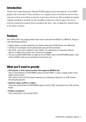
... an MTX/MRX system 14 About the priority mic 14 Connecting a PGX1 16 Indicator list 17 Status indicator 17 Indicator operation diagram 17 Alert list 18 Specifications 133 Dimensions 135 Included items • PGM1/PGX1 Installation Manual (this document) • PGM1/PGX1 Zone label (1 sheet) • PGM1: Gooseneck mic • PGX1: Connecting bracket, dedicated screws (8 pcs.), connection cable Firmware update MTX-MRX Editor is used to update the firmware of the following website.
... an MTX/MRX system 14 About the priority mic 14 Connecting a PGX1 16 Indicator list 17 Status indicator 17 Indicator operation diagram 17 Alert list 18 Specifications 133 Dimensions 135 Included items • PGM1/PGX1 Installation Manual (this document) • PGM1/PGX1 Zone label (1 sheet) • PGM1: Gooseneck mic • PGX1: Connecting bracket, dedicated screws (8 pcs.), connection cable Firmware update MTX-MRX Editor is used to update the firmware of the following website.
PGM1/PGX1 Installation Manual
Page 7
... played back using an SD card player. • Two PGX1 units can be added for the installing technician or the designer. What you to specify broadcast regions in one MTX/MRX system. This installation manual explains installation methods for each PGM1 unit, allowing you 'll need to read this manual, keep it for purchasing the Yamaha PGM1 paging station microphone or the PGX1...
... played back using an SD card player. • Two PGX1 units can be added for the installing technician or the designer. What you to specify broadcast regions in one MTX/MRX system. This installation manual explains installation methods for each PGM1 unit, allowing you 'll need to read this manual, keep it for purchasing the Yamaha PGM1 paging station microphone or the PGX1...
PGM1/PGX1 Installation Manual
Page 8
.../PGX1 Installation Manual NOTICE • Because the phantom power supply is not being supplied to the unit. • Do not connect any mic or device other indications, refer to switch the mic on the SD card. During broadcast, the indicator is possible. For other than one message can use MTX-MRX Editor to "MTX-MRX Editor User Guide." For details on , you should connect the mic when power...
.../PGX1 Installation Manual NOTICE • Because the phantom power supply is not being supplied to the unit. • Do not connect any mic or device other indications, refer to switch the mic on the SD card. During broadcast, the indicator is possible. For other than one message can use MTX-MRX Editor to "MTX-MRX Editor User Guide." For details on , you should connect the mic when power...
PGM1/PGX1 Installation Manual
Page 9
... ID; PGM1/PGX1 Installation Manual 9 remove the rubber cap to the bottom panel. Even if you have made the setting. • Do not set the UNIT ID to 7F. Switch Status The switch is in the upward (OFF) position. Making the settings Before changing the settings, turn off once. Controls and Connectors (PGM1) For details, see below. used in conjunction with device setting DIP switches 1-3 w which...
... ID; PGM1/PGX1 Installation Manual 9 remove the rubber cap to the bottom panel. Even if you have made the setting. • Do not set the UNIT ID to 7F. Switch Status The switch is in the upward (OFF) position. Making the settings Before changing the settings, turn off once. Controls and Connectors (PGM1) For details, see below. used in conjunction with device setting DIP switches 1-3 w which...
PGM1/PGX1 Installation Manual
Page 10
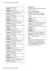
...." 10 PGM1/PGX1 Installation Manual Switch 123 Setting UNIT ID is "6x" Function The [UNIT ID] rotary switch setting has a range of 60 through 6F. Switch Setting 123 UNIT ID is "7x" Function The [UNIT ID] rotary switch setting has a range of 70 through 7F. • Switches 4-5 Not used for communicating with external devices. Leave these in MTX-MRX Editor (see "MTX-MRX Editor User Guide"). Switch 6 Setting PC Content...
...." 10 PGM1/PGX1 Installation Manual Switch 123 Setting UNIT ID is "6x" Function The [UNIT ID] rotary switch setting has a range of 60 through 6F. Switch Setting 123 UNIT ID is "7x" Function The [UNIT ID] rotary switch setting has a range of 70 through 7F. • Switches 4-5 Not used for communicating with external devices. Leave these in MTX-MRX Editor (see "MTX-MRX Editor User Guide"). Switch 6 Setting PC Content...
PGM1/PGX1 Installation Manual
Page 11
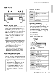
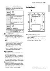
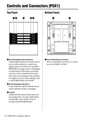
... for connection to the factory settings (page 13). Controls and Connectors (PGM1) • Switches 7-8 (START UP MODE) Specify how the unit is the clock master. r SYNC indicator This indicator shows the operating status of the Dante/NETWORK connector. Bottom Panel q q 8-pin dedicated connector This is connected correctly, the indicator flashes rapidly. If the Ethernet cable is a dedicated connector for connecting a Dante device such as the MRX7-D using...
... for connection to the factory settings (page 13). Controls and Connectors (PGM1) • Switches 7-8 (START UP MODE) Specify how the unit is the clock master. r SYNC indicator This indicator shows the operating status of the Dante/NETWORK connector. Bottom Panel q q 8-pin dedicated connector This is connected correctly, the indicator flashes rapidly. If the Ethernet cable is a dedicated connector for connecting a Dante device such as the MRX7-D using...
PGM1/PGX1 Installation Manual
Page 12
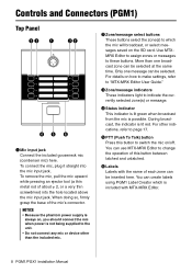
... make settings, refer to "MTX-MRX Editor User Guide." w Zone/message indicators These indicators light to these buttons. You can be selected at the same time. Only one broadcast zone can be inserted here. For details on the SD card. q 8-pin dedicated connector This is included with the name of each zone can be selected. Controls and Connectors (PGX1) Top Panel...
... make settings, refer to "MTX-MRX Editor User Guide." w Zone/message indicators These indicators light to these buttons. You can be selected at the same time. Only one broadcast zone can be inserted here. For details on the SD card. q 8-pin dedicated connector This is included with the name of each zone can be selected. Controls and Connectors (PGX1) Top Panel...
PGM1/PGX1 Installation Manual
Page 13
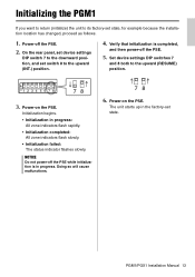
...: The status indicator flashes slowly. Set device settings DIP switches 7 and 8 both to the upward (INT.) position. 4. Power-on the PSE. PGM1/PGX1 Installation Manual 13 NOTICE Do not power-off the PSE while initialization is completed, and then power-off the PSE. 2. Doing so will cause malfunctions. 78 6. On the rear panel, set device settings DIP switch 7 to the downward position, and set switch 8 to the...
...: The status indicator flashes slowly. Set device settings DIP switches 7 and 8 both to the upward (INT.) position. 4. Power-on the PSE. PGM1/PGX1 Installation Manual 13 NOTICE Do not power-off the PSE while initialization is completed, and then power-off the PSE. 2. Doing so will cause malfunctions. 78 6. On the rear panel, set device settings DIP switch 7 to the downward position, and set switch 8 to the...

PGM1/PGX1 Installation Manual
Page 14
... can be connected to an MRX7-D or MTX5-D, one unit can be connected to "MTX-MRX Editor User Guide." Within the group, mics other mics in the group are given first-come first-served priority. NOTICE Do not connect or disconnect cables while the PSE is on. 14 PGM1/PGX1 Installation Manual When the priority mic begins broadcasting, the other than the priority mic are muted.
... can be connected to an MRX7-D or MTX5-D, one unit can be connected to "MTX-MRX Editor User Guide." Within the group, mics other mics in the group are given first-come first-served priority. NOTICE Do not connect or disconnect cables while the PSE is on. 14 PGM1/PGX1 Installation Manual When the priority mic begins broadcasting, the other than the priority mic are muted.
PGM1/PGX1 Installation Manual
Page 15
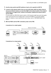
...100 meters SWR2100P-10G SWP1-16MMF XMV8280-D Computer PGM1/PGX1 Installation Manual 15 If the network switch does not support PoE, connect a PoE injector between the network switch and the PGM1. Connect the PGM1 to a port that do not supply power. Use the rotary switch and DIP switches ...Connecting the PGM1 to the network switch. Connect a PoE network switch that can work with Dante within the Dante network, and use an Ethernet cable to connect the PGM1 to an MTX/MRX system 1. With the PGM1 and the PSE connected, power-on how to synchronize each unit to "MTX-MRX Editor User Guide...
...100 meters SWR2100P-10G SWP1-16MMF XMV8280-D Computer PGM1/PGX1 Installation Manual 15 If the network switch does not support PoE, connect a PoE injector between the network switch and the PGM1. Connect the PGM1 to a port that do not supply power. Use the rotary switch and DIP switches ...Connecting the PGM1 to the network switch. Connect a PoE network switch that can work with Dante within the Dante network, and use an Ethernet cable to connect the PGM1 to an MTX/MRX system 1. With the PGM1 and the PSE connected, power-on how to synchronize each unit to "MTX-MRX Editor User Guide...

PGM1/PGX1 Installation Manual
Page 16
...it. PGX1 PGM1 5. Place the rubber cap that the surface of the body will not be connected on the right, and place the PGX1 to connect the PGM1 and PGX1. Use the included connection cable to ...panel of the PGX1. Place the connecting bracket between the two units, and fasten the screws (at the 8 locations shown below) on their back. 2. PGX1 Connecting bracket PGM1 Connecting bracket 6. Connecting a PGX1 Up to two PGX1 units can do so in a similar way. 16 PGM1/PGX1 Installation Manual NOTICE • Before making connections, detach the Ethernet cable and gooseneck mic...
...it. PGX1 PGM1 5. Place the rubber cap that the surface of the body will not be connected on the right, and place the PGX1 to connect the PGM1 and PGX1. Use the included connection cable to ...panel of the PGX1. Place the connecting bracket between the two units, and fasten the screws (at the 8 locations shown below) on their back. 2. PGX1 Connecting bracket PGM1 Connecting bracket 6. Connecting a PGX1 Up to two PGX1 units can do so in a similar way. 16 PGM1/PGX1 Installation Manual NOTICE • Before making connections, detach the Ethernet cable and gooseneck mic...

PGM1/PGX1 Installation Manual
Page 17
... priority mic Indicator operation diagram * Pressing PTT during broadcast will stop the broadcast. * It is not necessary to press PTT when finished. PTT: ON PTT: OFF PTT indicator (mic being operated) Green (Preparing) Flashing red (Broadcasting) Red Green Program Output Level 0 db Chime (SD) Mic Output/ Message (SD) Mic Input SD Input Range -∞ Attack Opening Chime PTT indicator Green (mic not being operated) Orange Closing Release...
... priority mic Indicator operation diagram * Pressing PTT during broadcast will stop the broadcast. * It is not necessary to press PTT when finished. PTT: ON PTT: OFF PTT indicator (mic being operated) Green (Preparing) Flashing red (Broadcasting) Red Green Program Output Level 0 db Chime (SD) Mic Output/ Message (SD) Mic Input SD Input Range -∞ Attack Opening Chime PTT indicator Green (mic not being operated) Orange Closing Release...

PGM1/PGX1 Installation Manual
Page 18
... same network. IP address was not set to alert number 8. Change the IP addresses or UNIT ID so that there are no duplicates. 18 PGM1/PGX1 Installation Manual Please check rear panel DIP switch 6 (IP SETTING). The UNIT ID is set to "00." If the problem cannot be solved, contact your Yamaha dealer. Alert list The following table lists the alerts generated by the PGM1...
... same network. IP address was not set to alert number 8. Change the IP addresses or UNIT ID so that there are no duplicates. 18 PGM1/PGX1 Installation Manual Please check rear panel DIP switch 6 (IP SETTING). The UNIT ID is set to "00." If the problem cannot be solved, contact your Yamaha dealer. Alert list The following table lists the alerts generated by the PGM1...

PGM1/PGX1 Installation Manual
Page 20
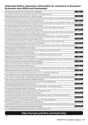
European models Purchaser/User Information specified in EN55103-2:2009. Conforms to Environments: E1, E2, E3 and E4 134 PGM1/PGX1 Installation Manual
European models Purchaser/User Information specified in EN55103-2:2009. Conforms to Environments: E1, E2, E3 and E4 134 PGM1/PGX1 Installation Manual
PGM1/PGX1 Installation Manual
Page 23
PGM1/PGX1 Installation Manual 137
PGM1/PGX1 Installation Manual 137


