

Owner's Manual
Page 1
U B NS-P320 (Including SW-P201 subwoofer system) HOME CINEMA 5.1CH SPEAKER PACKAGE OWNER'S MANUAL I
U B NS-P320 (Including SW-P201 subwoofer system) HOME CINEMA 5.1CH SPEAKER PACKAGE OWNER'S MANUAL I
Owner's Manual
Page 2
NO USER-SERVICEABLE PARTS INSIDE. IMPORTANT Please record the serial number of power supply to insert the plug fully into this can fall , causing serious injury to a child or adult, and serious damage to . 4 Follow Instructions - WARNING TO REDUCE THE RISK OF FIRE OR ELECTRIC SHOCK, DO NOT EXPOSE THIS APPLIANCE TO RAIN OR MOISTURE. All warnings on the product and in the space below. Unplug this product from the wall outlet before the product is operated. 2 Retain Instructions - and the like. 8 Accessories - Use only with the product. If you are not sure of the type of ...
NO USER-SERVICEABLE PARTS INSIDE. IMPORTANT Please record the serial number of power supply to insert the plug fully into this can fall , causing serious injury to a child or adult, and serious damage to . 4 Follow Instructions - WARNING TO REDUCE THE RISK OF FIRE OR ELECTRIC SHOCK, DO NOT EXPOSE THIS APPLIANCE TO RAIN OR MOISTURE. All warnings on the product and in the space below. Unplug this product from the wall outlet before the product is operated. 2 Retain Instructions - and the like. 8 Accessories - Use only with the product. If you are not sure of the type of ...
Owner's Manual
Page 3
...by the manufacturer. 23 Heat - Failure to follow instructions could void your sensitive hearing. We Want You Listening For A Lifetime YAMAHA and the Electronic Industries Association's Consumer Electronics Group want you can be situated away from the wall outlet and refer servicing to ...interference will not result in FCC Regulations, Part 15 for Class "B" digital devices. If the antenna lead-in is too late, YAMAHA and the Electronic Industries Association's Consumer Electronics Group recommend you to get the most importantly, without annoying blaring or distortion - this ...
...by the manufacturer. 23 Heat - Failure to follow instructions could void your sensitive hearing. We Want You Listening For A Lifetime YAMAHA and the Electronic Industries Association's Consumer Electronics Group want you can be situated away from the wall outlet and refer servicing to ...interference will not result in FCC Regulations, Part 15 for Class "B" digital devices. If the antenna lead-in is too late, YAMAHA and the Electronic Industries Association's Consumer Electronics Group recommend you to get the most importantly, without annoying blaring or distortion - this ...
Owner's Manual
Page 4
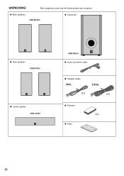
UNPACKING After unpacking, check that the following items are contained. G Main speakers G Subwoofer G Rear speakers G Center speaker G Audio connection cable G Speaker cables [4m] [15m] X 3 X 2 G Fastener X 4 G Pads IV
UNPACKING After unpacking, check that the following items are contained. G Main speakers G Subwoofer G Rear speakers G Center speaker G Audio connection cable G Speaker cables [4m] [15m] X 3 X 2 G Fastener X 4 G Pads IV
Owner's Manual
Page 5
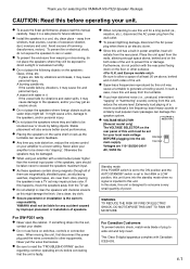
...shock. ● Do not place the speakers where foreign objects such as water drips might fall. If this happens, move this unit. YAMAHA shall not be liable for any accident caused by vibrations, it may impair picture color. Never pull the wires themselves. ● Be... to read the "TROUBLESHOOTING" section regarding common operating errors before operating your unit. ● To assure the finest performance, please read this YAMAHA NS-P320 Speaker Package. In such a case, move the speakers away from the wall outlet. ● To prevent lightning damage, disconnect the AC ...
...shock. ● Do not place the speakers where foreign objects such as water drips might fall. If this happens, move this unit. YAMAHA shall not be liable for any accident caused by vibrations, it may impair picture color. Never pull the wires themselves. ● Be... to read the "TROUBLESHOOTING" section regarding common operating errors before operating your unit. ● To assure the finest performance, please read this YAMAHA NS-P320 Speaker Package. In such a case, move the speakers away from the wall outlet. ● To prevent lightning damage, disconnect the AC ...
Owner's Manual
Page 6
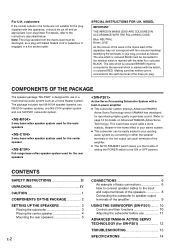
SPECIAL INSTRUCTIONS FOR U.K. COMPONENTS OF THE PACKAGE The speaker package "NS-P320" is marked with the coloured markings identifying the terminals in your existing audio system by connecting to either the speaker terminals or the line ...power amplifier ● This subwoofer system employs Advanced YAMAHA Active Servo Technology which is designed for use 11 ADVANCED YAMAHA ACTIVE SERVO TECHNOLOGY (for SW-P201 12 TROUBLESHOOTING 13 SPECIFICATIONS 14 The package includes two NS-M104 speaker systems, two NS-E104 speaker systems, one NS-C104 speaker system and one SW-P201 subwoofer ...
SPECIAL INSTRUCTIONS FOR U.K. COMPONENTS OF THE PACKAGE The speaker package "NS-P320" is marked with the coloured markings identifying the terminals in your existing audio system by connecting to either the speaker terminals or the line ...power amplifier ● This subwoofer system employs Advanced YAMAHA Active Servo Technology which is designed for use 11 ADVANCED YAMAHA ACTIVE SERVO TECHNOLOGY (for SW-P201 12 TROUBLESHOOTING 13 SPECIFICATIONS 14 The package includes two NS-M104 speaker systems, two NS-E104 speaker systems, one NS-C104 speaker system and one SW-P201 subwoofer ...
Owner's Manual
Page 7
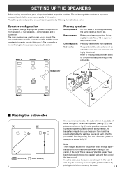
Rear speakers: Behind your listening position by following the instructions below for a recommended positioning of and at an angle as the TV set Rear R Rear L Ⅵ Placing the subwoofer Å ı ( : Subwoofer, : Main speaker) It is recommended to "Placing the subwoofer" below . Refer to place the subwoofer on the outside of the room. To prevent this system. bass sounds from happening, face the subwoofer system at approximately the same height as shown in fig. Å. It also may die because the sound from the floor. Speaker configuration This speaker ...
Rear speakers: Behind your listening position by following the instructions below for a recommended positioning of and at an angle as the TV set Rear R Rear L Ⅵ Placing the subwoofer Å ı ( : Subwoofer, : Main speaker) It is recommended to "Placing the subwoofer" below . Refer to place the subwoofer on the outside of the room. To prevent this system. bass sounds from happening, face the subwoofer system at approximately the same height as shown in fig. Å. It also may die because the sound from the floor. Speaker configuration This speaker ...
Owner's Manual
Page 8
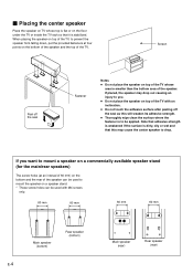
Ⅵ Placing the center speaker Place the speaker on TV whose area is smaller than the bottom area of the TV with M4 screws only. 60 mm 60 mm 60 mm 60 mm Main speaker (bottom) Rear speaker (bottom) E-4 Main speaker (rear) Rear speaker (rear) Note that adhesive strength is weakened if the surface is dirty, oily or wet and that it is to be used with an inclination. ● Do not touch the adhesive surface after peeling off the seal Fastener Notes ● Do not place the speaker on top of the TV whose top is flat or on the bottom of the speaker and the top of the ...
Ⅵ Placing the center speaker Place the speaker on TV whose area is smaller than the bottom area of the TV with M4 screws only. 60 mm 60 mm 60 mm 60 mm Main speaker (bottom) Rear speaker (bottom) E-4 Main speaker (rear) Rear speaker (rear) Note that adhesive strength is weakened if the surface is dirty, oily or wet and that it is to be used with an inclination. ● Do not touch the adhesive surface after peeling off the seal Fastener Notes ● Do not place the speaker on top of the TV whose top is flat or on the bottom of the speaker and the top of the ...

Owner's Manual
Page 9
Do not mount them on the wall. Longterm use the lower holes on the rear of the rear speakers to prevent the rear speakers from tripping over loose speaker cables, fix them to the wall. ● Select a proper position on the wall to a wall with soft surface material. If mounted, the screws may come out of the flimsy surface and the speakers may cause them to fall. ● To avoid accidents resulting from moving by 2 using the holes on the speakers' back panels Diam. 3.5 to 4 mm Min. 20 mm 6 mm Tapping screw (Available at the hardware store) Note It is recommended that you ...
Do not mount them on the wall. Longterm use the lower holes on the rear of the rear speakers to prevent the rear speakers from tripping over loose speaker cables, fix them to the wall. ● Select a proper position on the wall to a wall with soft surface material. If mounted, the screws may come out of the flimsy surface and the speakers may cause them to fall. ● To avoid accidents resulting from moving by 2 using the holes on the speakers' back panels Diam. 3.5 to 4 mm Min. 20 mm 6 mm Tapping screw (Available at the hardware store) Note It is recommended that you ...
Owner's Manual
Page 10
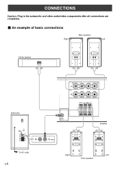
SUB WOOFER OUTPUT Amplifier /MONO Right Left Rear speakers CONNECTIONS Caution: Plug in the subwoofer and other audio/video components after all connections are completed. Ⅵ An example of basic connections Main speakers Right Left Center speaker Subwoofer POWER ON OFF VOLUME STANDBY-RED ON-GREEN AUTO STANDBY HIGH LOW OFF 0 I0 INPUT2 /MONO INPUT1 FROM AMPLIFIER OUTPUT TO SPEAKERS INPUT2 To AC outlet E-6 R+ A SPEAKERS - - +L MAIN B IMPEDA EO SET B MA CENTER REAR R (SURROUND) L CEN RE + MAIN A OR B: 4 M A + B: 8 M CENTER : 6 M REAR :6 M -
SUB WOOFER OUTPUT Amplifier /MONO Right Left Rear speakers CONNECTIONS Caution: Plug in the subwoofer and other audio/video components after all connections are completed. Ⅵ An example of basic connections Main speakers Right Left Center speaker Subwoofer POWER ON OFF VOLUME STANDBY-RED ON-GREEN AUTO STANDBY HIGH LOW OFF 0 I0 INPUT2 /MONO INPUT1 FROM AMPLIFIER OUTPUT TO SPEAKERS INPUT2 To AC outlet E-6 R+ A SPEAKERS - - +L MAIN B IMPEDA EO SET B MA CENTER REAR R (SURROUND) L CEN RE + MAIN A OR B: 4 M A + B: 8 M CENTER : 6 M REAR :6 M -
Owner's Manual
Page 11
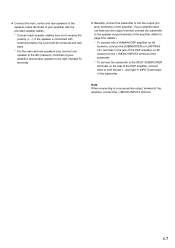
... not have any line output terminal, connect the subwoofer to the speaker output terminals of the amplifier. (Refer to page 9 for details.) * To connect with a YAMAHA DSP amplifier (or AV receiver), connect the SUBWOOFER (or LOW PASS etc.) terminal on the rear of the DSP amplifier (or AV receiver) to the...
... not have any line output terminal, connect the subwoofer to the speaker output terminals of the amplifier. (Refer to page 9 for details.) * To connect with a YAMAHA DSP amplifier (or AV receiver), connect the SUBWOOFER (or LOW PASS etc.) terminal on the rear of the DSP amplifier (or AV receiver) to the...
Owner's Manual
Page 12
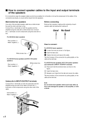
... speakers For connections, keep the speaker cables as short as this could damage the speaker or the amplifier, or both of them. For NS-E104 (rear speaker), NS-C104 (center speaker) and subwoofer's INPUT 1/OUTPUT terminals 1 Press and hold the terminal's tab, as shown in the figure. 2 ...and secure the cable. Ⅵ How to connect speaker cables to connect: 3 2 White broken line For NS-E104 (rear speaker) and NS-C104 (center speaker) Red: positive (+) Black: negative (-) White broken line For NS-M104 (main speaker) 1 Loosen the knob, as shown in the figure. 2 Insert the bare wire. 3...
... speakers For connections, keep the speaker cables as short as this could damage the speaker or the amplifier, or both of them. For NS-E104 (rear speaker), NS-C104 (center speaker) and subwoofer's INPUT 1/OUTPUT terminals 1 Press and hold the terminal's tab, as shown in the figure. 2 ...and secure the cable. Ⅵ How to connect speaker cables to connect: 3 2 White broken line For NS-E104 (rear speaker) and NS-C104 (center speaker) Red: positive (+) Black: negative (-) White broken line For NS-M104 (main speaker) 1 Loosen the knob, as shown in the figure. 2 Insert the bare wire. 3...
Owner's Manual
Page 13
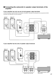
Ⅵ Connecting the subwoofer to the main speakers. Left main speaker Right main speaker Subwoofer POWER ON OFF VOLUME STANDBY-RED ON-GREEN AUTO STANDBY HIGH LOW OFF 0 I0 INPUT2 /MONO INPUT1 FROM AMPLIFIER OUTPUT TO SPEAKERS INPUT1 FROM AMPLIFIER OUTPUT TO SPEAKERS Speaker output terminals To AC outlet Amplifier If your amplifier has only one set of main speaker output terminals Connect the speaker output terminals of the amplifier to the INPUT1 terminals of the subwoofer, and connect the OUTPUT terminals of the subwoofer to speaker output terminals of the amplifier If...
Ⅵ Connecting the subwoofer to the main speakers. Left main speaker Right main speaker Subwoofer POWER ON OFF VOLUME STANDBY-RED ON-GREEN AUTO STANDBY HIGH LOW OFF 0 I0 INPUT2 /MONO INPUT1 FROM AMPLIFIER OUTPUT TO SPEAKERS INPUT1 FROM AMPLIFIER OUTPUT TO SPEAKERS Speaker output terminals To AC outlet Amplifier If your amplifier has only one set of main speaker output terminals Connect the speaker output terminals of the amplifier to the INPUT1 terminals of the subwoofer, and connect the OUTPUT terminals of the subwoofer to speaker output terminals of the amplifier If...
Owner's Manual
Page 14
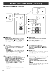
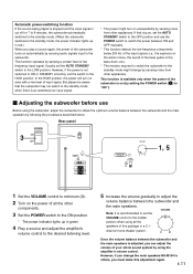
Standby mode The subwoofer is still using a small amount of the subwoofer. 2 Power indicator Lights up GREEN when the POWER switch is set to the ON position and goes off the power of power in the OFF position. Signals from the amplifier. 5 INPUT1 (FROM AMPLIFIER) terminals Used to change the setting of the subwoofer is in this mode. Set this switch to the OFF position to turn on the power of the amplifier. 6 OUTPUT (TO SPEAKERS) terminals Can be used for connecting to the main speakers. Turn the control clockwise to increase the volume, and counterclockwise to decrease the ...
Standby mode The subwoofer is still using a small amount of the subwoofer. 2 Power indicator Lights up GREEN when the POWER switch is set to the ON position and goes off the power of power in the OFF position. Signals from the amplifier. 5 INPUT1 (FROM AMPLIFIER) terminals Used to change the setting of the subwoofer is in this mode. Set this switch to the OFF position to turn on the power of the amplifier. 6 OUTPUT (TO SPEAKERS) terminals Can be used for connecting to the main speakers. Turn the control clockwise to increase the volume, and counterclockwise to decrease the ...
Owner's Manual
Page 15
... on unexpectedly by sensing noise from other appliances. However, if the power is an extremely low input signal. * The power might change the main speakers NS-M104 to adjust the volume balance between ON and OFF manually. * This function detects the low-frequency components below . This function is available only when...
... on unexpectedly by sensing noise from other appliances. However, if the power is an extremely low input signal. * The power might change the main speakers NS-M104 to adjust the volume balance between ON and OFF manually. * This function detects the low-frequency components below . This function is available only when...
Owner's Manual
Page 16
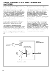
... amplifier and a speaker cabinet with the Helmholtz resonator, reproduce an extremely wide range of frequencies with the conventional Yamaha Active Servo Technology, resulting in the correct proportion to accomplish this problem that exists within the cabinet can, according... to generate precise, low-amplitude, lowfrequency waves with respect to select an optimum value for speaker impedance variation. Advanced Yamaha Active Servo Technology - High-amplitude bass sound Cabinet Port Advanced Negativeimpedance Converter Active Servo Processing Amplifier Air woofer (Helmholtz resonator...
... amplifier and a speaker cabinet with the Helmholtz resonator, reproduce an extremely wide range of frequencies with the conventional Yamaha Active Servo Technology, resulting in the correct proportion to accomplish this problem that exists within the cabinet can, according... to generate precise, low-amplitude, lowfrequency waves with respect to select an optimum value for speaker impedance variation. Advanced Yamaha Active Servo Technology - High-amplitude bass sound Cabinet Port Advanced Negativeimpedance Converter Active Servo Processing Amplifier Air woofer (Helmholtz resonator...
Owner's Manual
Page 17
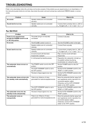
... AUTO STANDBY switch to Do Connect it securely. TROUBLESHOOTING Refer to the chart below do not help, disconnect the power cord and contact your authorized YAMAHA dealer or service center. If the problem you are experiencing is L (left ) to L, R (right) to R, "+" to "+" and "-" to "-". Cause Speaker cables are not connected correctly...
... AUTO STANDBY switch to Do Connect it securely. TROUBLESHOOTING Refer to the chart below do not help, disconnect the power cord and contact your authorized YAMAHA dealer or service center. If the problem you are experiencing is L (left ) to L, R (right) to R, "+" to "+" and "-" to "-". Cause Speaker cables are not connected correctly...
Owner's Manual
Page 18
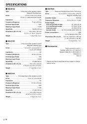
...H x D 440 x 85 x 122 mm (17-5/16" x 3-5/16" x 4-13/16") Weight 1.7 kg (3 lbs. 11 oz.) Ⅵ SW-P201 Type Advanced Yamaha Active Servo Technology Driver 16 cm (6-5/16") cone woofer (JA1678) Magnetic shielding type Amplifier Output 50W/5Ω Frequency Response 30 Hz-200 Hz (-10 dB...dB/2.83V/m Dimensions (W x H x D 140 x 300 x 167 mm (5-1/2" x 11-13/16" x 6-9/16") Weight 1.9 kg (4 lbs. 3 oz.) Ⅵ NS-C104 Type 2-way bass-reflex speaker system Magnetic shielding type Driver 7 cm (2-3/4") cone woofer x 3 1.5 cm (5/8") tweeter Impedance 6Ω Frequency Response 95 Hz to 20 kHz...
...H x D 440 x 85 x 122 mm (17-5/16" x 3-5/16" x 4-13/16") Weight 1.7 kg (3 lbs. 11 oz.) Ⅵ SW-P201 Type Advanced Yamaha Active Servo Technology Driver 16 cm (6-5/16") cone woofer (JA1678) Magnetic shielding type Amplifier Output 50W/5Ω Frequency Response 30 Hz-200 Hz (-10 dB...dB/2.83V/m Dimensions (W x H x D 140 x 300 x 167 mm (5-1/2" x 11-13/16" x 6-9/16") Weight 1.9 kg (4 lbs. 3 oz.) Ⅵ NS-C104 Type 2-way bass-reflex speaker system Magnetic shielding type Driver 7 cm (2-3/4") cone woofer x 3 1.5 cm (5/8") tweeter Impedance 6Ω Frequency Response 95 Hz to 20 kHz...

Owner's Manual
Page 19
... LTD. 135 MILNER AVE., SCARBOROUGH, ONTARIO M1S 3R1, CANADA YAMAHA ELECTRONIK EUROPA G.m.b.H. OF GERMANY YAMAHA ELECTRONIQUE FRANCE S.A. RUE AMBROISE CROIZAT BP70 CROISSY-BEAUBOURG 77312 MARNE-LA-VALLEE CEDEX02, FRANCE YAMAHA ELECTRONICS (UK) LTD. YAMAHA HOUSE, 200 RICKMANSWORTH ROAD WATFORD, HERTS WD1 7JS, ENGLAND YAMAHA SCANDINAVIA A.B. SIEMENSSTR, 22-34, 25462 RELLINGEN, BEI HAMBURG, F.R. J A WETTERGRENS GATA 1, BOX...
... LTD. 135 MILNER AVE., SCARBOROUGH, ONTARIO M1S 3R1, CANADA YAMAHA ELECTRONIK EUROPA G.m.b.H. OF GERMANY YAMAHA ELECTRONIQUE FRANCE S.A. RUE AMBROISE CROIZAT BP70 CROISSY-BEAUBOURG 77312 MARNE-LA-VALLEE CEDEX02, FRANCE YAMAHA ELECTRONICS (UK) LTD. YAMAHA HOUSE, 200 RICKMANSWORTH ROAD WATFORD, HERTS WD1 7JS, ENGLAND YAMAHA SCANDINAVIA A.B. SIEMENSSTR, 22-34, 25462 RELLINGEN, BEI HAMBURG, F.R. J A WETTERGRENS GATA 1, BOX...