

Owner's Manual
Page 1
U B NS-P320 (Including SW-P201 subwoofer system) HOME CINEMA 5.1CH SPEAKER PACKAGE OWNER'S MANUAL I
U B NS-P320 (Including SW-P201 subwoofer system) HOME CINEMA 5.1CH SPEAKER PACKAGE OWNER'S MANUAL I
Owner's Manual
Page 4
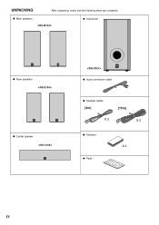
UNPACKING After unpacking, check that the following items are contained. G Main speakers G Subwoofer G Rear speakers G Center speaker G Audio connection cable G Speaker cables [4m] [15m] X 3 X 2 G Fastener X 4 G Pads IV
UNPACKING After unpacking, check that the following items are contained. G Main speakers G Subwoofer G Rear speakers G Center speaker G Audio connection cable G Speaker cables [4m] [15m] X 3 X 2 G Fastener X 4 G Pads IV
Owner's Manual
Page 5
...only) The VOLTAGE SELECTOR on your dealer. ● Do not use this unit must be taken never to this YAMAHA NS-P320 Speaker Package. Furthermore, do not expose the speakers to clean the speakers with a rated output power higher than the nominal input power of plug to the ON position and the AUTO ...Never allow a space of them . near a TV set to the HIGH or LOW position, this unit turns into "clipping". YAMAHA shall not be driven into the standby mode when no signal is designed to the speakers, and/or you note distortion, reduce the volume control on the rear panel of...
...only) The VOLTAGE SELECTOR on your dealer. ● Do not use this unit must be taken never to this YAMAHA NS-P320 Speaker Package. Furthermore, do not expose the speakers to clean the speakers with a rated output power higher than the nominal input power of plug to the ON position and the AUTO ...Never allow a space of them . near a TV set to the HIGH or LOW position, this unit turns into "clipping". YAMAHA shall not be driven into the standby mode when no signal is designed to the speakers, and/or you note distortion, reduce the volume control on the rear panel of...
Owner's Manual
Page 6
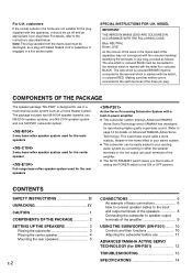
...: The plug severed from the mains lead must be cut off and an appropriate 3 pin plug fitted. COMPONENTS OF THE PACKAGE The speaker package "NS-P320" is designed for the plug supplied with this apparatus may not correspond with the letter N or coloured BLACK. CONTENTS SAFETY INSTRUCTIONS II UNPACKING... proceed as follows: The wire which is connected to the earth terminal of this appliance, it should be connected to the terminal which YAMAHA has developed for reproducing higher quality super-bass sound. (Refer to the ON or OFF position. MODEL IMPORTANT: THE WIRES IN MAINS LEAD...
...: The plug severed from the mains lead must be cut off and an appropriate 3 pin plug fitted. COMPONENTS OF THE PACKAGE The speaker package "NS-P320" is designed for the plug supplied with this apparatus may not correspond with the letter N or coloured BLACK. CONTENTS SAFETY INSTRUCTIONS II UNPACKING... proceed as follows: The wire which is connected to the earth terminal of this appliance, it should be connected to the terminal which YAMAHA has developed for reproducing higher quality super-bass sound. (Refer to the ON or OFF position. MODEL IMPORTANT: THE WIRES IN MAINS LEAD...
Owner's Manual
Page 7
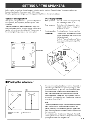
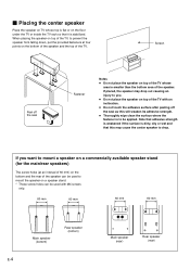
...sound from it controls the whole sound quality of the room. Speaker configuration This speaker package employs a 6 speaker configuration: 2 main speakers, 2 rear speakers, a center speaker and a subwoofer. bass sounds from the floor. Center speaker: Precisely between two parallel walls and they cancel the bass ... because it and the sound reflected by placing bookshelves etc. along the walls. Place the speakers depending on the outside of the subwoofer. Rear speakers: Behind your listening position, facing slightly inward. Subwoofer: The position of and at an...
...sound from it controls the whole sound quality of the room. Speaker configuration This speaker package employs a 6 speaker configuration: 2 main speakers, 2 rear speakers, a center speaker and a subwoofer. bass sounds from the floor. Center speaker: Precisely between two parallel walls and they cancel the bass ... because it and the sound reflected by placing bookshelves etc. along the walls. Place the speakers depending on the outside of the subwoofer. Rear speakers: Behind your listening position, facing slightly inward. Subwoofer: The position of and at an...
Owner's Manual
Page 8
... the fastener is dirty, oily or wet and that adhesive strength is weakened if the surface is to mount the speaker on the bottom of the speaker and the top of the speaker can be used with an inclination. ● Do not touch the adhesive surface after peeling off the seal Fastener Notes... ● Do not place the speaker on top of the TV whose top is flat or on the floor under the TV or inside the TV rack so that it is ...
... the fastener is dirty, oily or wet and that adhesive strength is weakened if the surface is to mount the speaker on the bottom of the speaker and the top of the speaker can be used with an inclination. ● Do not touch the adhesive surface after peeling off the seal Fastener Notes... ● Do not place the speaker on top of the TV whose top is flat or on the floor under the TV or inside the TV rack so that it is ...

Owner's Manual
Page 9
... protruding screws. * Make sure that no one will injure his/her head or face. Longterm use the lower holes on the wall to mount the speaker so that the screws are securely caught by vibrations. 2 Fasten screws into a firm wall or wall support as shown in the figure. Holes To mount... the rear speakers on a wall by 2 using the holes on the speakers' back panels Diam. 3.5 to 4 mm Min. 20 mm 6 mm Tapping screw (Available at the hardware store) Note It is recommended that...
... protruding screws. * Make sure that no one will injure his/her head or face. Longterm use the lower holes on the wall to mount the speaker so that the screws are securely caught by vibrations. 2 Fasten screws into a firm wall or wall support as shown in the figure. Holes To mount... the rear speakers on a wall by 2 using the holes on the speakers' back panels Diam. 3.5 to 4 mm Min. 20 mm 6 mm Tapping screw (Available at the hardware store) Note It is recommended that...
Owner's Manual
Page 10
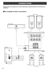
CONNECTIONS Caution: Plug in the subwoofer and other audio/video components after all connections are completed. Ⅵ An example of basic connections Main speakers Right Left Center speaker Subwoofer POWER ON OFF VOLUME STANDBY-RED ON-GREEN AUTO STANDBY HIGH LOW OFF 0 I0 INPUT2 /MONO INPUT1 FROM AMPLIFIER OUTPUT TO SPEAKERS INPUT2 To AC outlet E-6 R+ A SPEAKERS - - +L MAIN B IMPEDA EO SET B MA CENTER REAR R (SURROUND) L CEN RE + MAIN A OR B: 4 M A + B: 8 M CENTER : 6 M REAR :6 M - SUB WOOFER OUTPUT Amplifier /MONO Right Left Rear speakers
CONNECTIONS Caution: Plug in the subwoofer and other audio/video components after all connections are completed. Ⅵ An example of basic connections Main speakers Right Left Center speaker Subwoofer POWER ON OFF VOLUME STANDBY-RED ON-GREEN AUTO STANDBY HIGH LOW OFF 0 I0 INPUT2 /MONO INPUT1 FROM AMPLIFIER OUTPUT TO SPEAKERS INPUT2 To AC outlet E-6 R+ A SPEAKERS - - +L MAIN B IMPEDA EO SET B MA CENTER REAR R (SURROUND) L CEN RE + MAIN A OR B: 4 M A + B: 8 M CENTER : 6 M REAR :6 M - SUB WOOFER OUTPUT Amplifier /MONO Right Left Rear speakers
Owner's Manual
Page 11
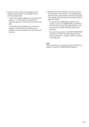
...the polarity (+, -). E-7 If your amplifier does not have any line output terminal, connect the subwoofer to the speaker output terminals of the amplifier. (Refer to page 9 for details.) * To connect with a YAMAHA DSP amplifier (or AV receiver), connect the SUBWOOFER (or LOW PASS etc.) terminal on the rear of the... left (marked L) terminals of your amplifier with reversed polarity, the sound will be unnatural and lack bass. * For the main and rear speakers only, connect one speaker to the left L and right R INPUT2 terminals of the subwoofer. ● Connect the main, center and rear...
...the polarity (+, -). E-7 If your amplifier does not have any line output terminal, connect the subwoofer to the speaker output terminals of the amplifier. (Refer to page 9 for details.) * To connect with a YAMAHA DSP amplifier (or AV receiver), connect the SUBWOOFER (or LOW PASS etc.) terminal on the rear of the... left (marked L) terminals of your amplifier with reversed polarity, the sound will be unnatural and lack bass. * For the main and rear speakers only, connect one speaker to the left L and right R INPUT2 terminals of the subwoofer. ● Connect the main, center and rear...
Owner's Manual
Page 12
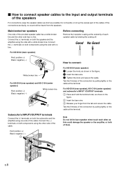
... terminals on the cable at the terminal. Ⅵ How to connect speaker cables to connect: 3 2 White broken line For NS-E104 (rear speaker) and NS-C104 (center speaker) Red: positive (+) Black: negative (-) White broken line For NS-M104 (main speaker) 1 Loosen the knob, as shown in the figure. 2 Insert the... excess part of the connection by pulling lightly on both the speaker and the amplifier using the side with a white broken line. Test the firmness of the cables. For NS-E104 (rear speaker), NS-C104 (center speaker) and subwoofer's INPUT 1/OUTPUT terminals 1 Press and hold the...
... terminals on the cable at the terminal. Ⅵ How to connect speaker cables to connect: 3 2 White broken line For NS-E104 (rear speaker) and NS-C104 (center speaker) Red: positive (+) Black: negative (-) White broken line For NS-M104 (main speaker) 1 Loosen the knob, as shown in the figure. 2 Insert the... excess part of the connection by pulling lightly on both the speaker and the amplifier using the side with a white broken line. Test the firmness of the cables. For NS-E104 (rear speaker), NS-C104 (center speaker) and subwoofer's INPUT 1/OUTPUT terminals 1 Press and hold the...
Owner's Manual
Page 13
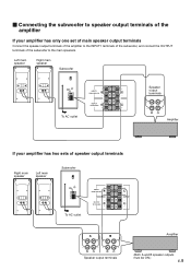
... 0 I0 INPUT2 /MONO INPUT1 FROM AMPLIFIER OUTPUT TO SPEAKERS INPUT1 FROM AMPLIFIER OUTPUT TO SPEAKERS Speaker output terminals To AC outlet Amplifier If your amplifier has only one set of main speaker output terminals Connect the speaker output terminals of the amplifier to the INPUT1 terminals of... the subwoofer, and connect the OUTPUT terminals of the subwoofer to speaker output terminals of the amplifier If your amplifier has two sets of speaker output terminals Right main speaker Left main speaker Subwoofer POWER ON OFF VOLUME STANDBY-RED ON-GREEN AUTO STANDBY HIGH LOW...
... 0 I0 INPUT2 /MONO INPUT1 FROM AMPLIFIER OUTPUT TO SPEAKERS INPUT1 FROM AMPLIFIER OUTPUT TO SPEAKERS Speaker output terminals To AC outlet Amplifier If your amplifier has only one set of main speaker output terminals Connect the speaker output terminals of the amplifier to the INPUT1 terminals of... the subwoofer, and connect the OUTPUT terminals of the subwoofer to speaker output terminals of the amplifier If your amplifier has two sets of speaker output terminals Right main speaker Left main speaker Subwoofer POWER ON OFF VOLUME STANDBY-RED ON-GREEN AUTO STANDBY HIGH LOW...
Owner's Manual
Page 14
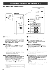
... Signals from the amplifier. 5 INPUT1 (FROM AMPLIFIER) terminals Used to connect the subwoofer with the speaker terminals of the amplifier. 6 OUTPUT (TO SPEAKERS) terminals Can be used for connecting to the main speakers. If you are sent to these terminals. 7 VOLUME control Adjusts the volume level. Consult your ...OFF 220V-240V 110V-120V VOLUME STANDBY-RED ON-GREEN AUTO STANDBY HIGH LOW OFF 0 I0 INPUT2 /MONO INPUT1 FROM AMPLIFIER OUTPUT TO SPEAKERS 220V-240V 110V-120V 8 VOLUME 2 3 4 STANDBY-RED ON-GREEN AUTO STANDBY HIGH LOW OFF 0 I0 INPUT2 /MONO 7 5 INPUT1 FROM AMPLIFIER...
... Signals from the amplifier. 5 INPUT1 (FROM AMPLIFIER) terminals Used to connect the subwoofer with the speaker terminals of the amplifier. 6 OUTPUT (TO SPEAKERS) terminals Can be used for connecting to the main speakers. If you are sent to these terminals. 7 VOLUME control Adjusts the volume level. Consult your ...OFF 220V-240V 110V-120V VOLUME STANDBY-RED ON-GREEN AUTO STANDBY HIGH LOW OFF 0 I0 INPUT2 /MONO INPUT1 FROM AMPLIFIER OUTPUT TO SPEAKERS 220V-240V 110V-120V 8 VOLUME 2 3 4 STANDBY-RED ON-GREEN AUTO STANDBY HIGH LOW OFF 0 I0 INPUT2 /MONO 7 5 INPUT1 FROM AMPLIFIER...
Owner's Manual
Page 15
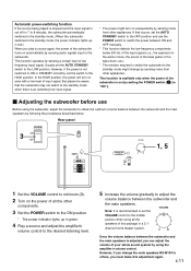
...that the subwoofer may not switch to the standby mode when there is an extremely low input signal. * The power might change the main speakers NS-M104 to others, you can adjust the volume of your whole sound system by sensing a certain level of low frequency input signal. Note: ...set the AUTO STANDBY switch to the HIGH position. channel home theater system. 0 I0 Once the volume balance between the subwoofer and the main speakers is adjusted, you must make this package in a 5.1- Usually set the VOLUME VOLUME control to the middle position when using the amplifier's volume ...
...that the subwoofer may not switch to the standby mode when there is an extremely low input signal. * The power might change the main speakers NS-M104 to others, you can adjust the volume of your whole sound system by sensing a certain level of low frequency input signal. Note: ...set the AUTO STANDBY switch to the HIGH position. channel home theater system. 0 I0 Once the volume balance between the subwoofer and the main speakers is adjusted, you must make this package in a 5.1- Usually set the VOLUME VOLUME control to the middle position when using the amplifier's volume ...
Owner's Manual
Page 16
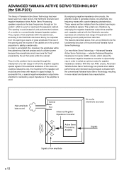
... can , therefore, by the air that is used instead of, and performs the functions of frequencies with the conventional Yamaha Active Servo Technology, resulting in a conventionally designed speaker system. Active Servo Processing speakers reproduce the bass frequencies through the employment of the opening in the correct proportion to dynamically vary in which is...
... can , therefore, by the air that is used instead of, and performs the functions of frequencies with the conventional Yamaha Active Servo Technology, resulting in a conventionally designed speaker system. Active Servo Processing speakers reproduce the bass frequencies through the employment of the opening in the correct proportion to dynamically vary in which is...
Owner's Manual
Page 17
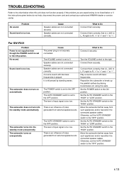
...low. The AUTO STANDBY switch is set to the "OFF" position. Reposition the subwoofer or break up the parallel surface by standing waves. Speaker cables are not connected securely. The subwoofer turns on automatically. The level of noise generated from external appliances etc. Play a source sound with...Connect it securely. Set the AUTO STANDBY switch to the chart below do not help, disconnect the power cord and contact your authorized YAMAHA dealer or service center. Cause The power plug is not listed below or if the instructions given below when this unit does not ...
...low. The AUTO STANDBY switch is set to the "OFF" position. Reposition the subwoofer or break up the parallel surface by standing waves. Speaker cables are not connected securely. The subwoofer turns on automatically. The level of noise generated from external appliances etc. Play a source sound with...Connect it securely. Set the AUTO STANDBY switch to the chart below do not help, disconnect the power cord and contact your authorized YAMAHA dealer or service center. Cause The power plug is not listed below or if the instructions given below when this unit does not ...
Owner's Manual
Page 18
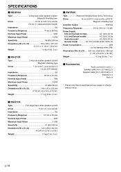
...Yamaha Active Servo Technology Driver 16 cm (6-5/16") cone woofer (JA1678) Magnetic shielding type Amplifier Output 50W/5Ω Frequency Response 30 Hz-200 Hz (-10 dB) Power Supply USA and Canada models AC 120V, 60 Hz U.K. SPECIFICATIONS Ⅵ NS-M104 Type 2-way bass-reflex speaker...(W x H x D 140 x 300 x 167 mm (5-1/2" x 11-13/16" x 6-9/16") Weight 1.9 kg (4 lbs. 3 oz.) Ⅵ NS-C104 Type 2-way bass-reflex speaker system Magnetic shielding type Driver 7 cm (2-3/4") cone woofer x 3 1.5 cm (5/8") tweeter Impedance 6Ω Frequency Response 95 Hz to 20 kHz Nominal Input Power ...
...Yamaha Active Servo Technology Driver 16 cm (6-5/16") cone woofer (JA1678) Magnetic shielding type Amplifier Output 50W/5Ω Frequency Response 30 Hz-200 Hz (-10 dB) Power Supply USA and Canada models AC 120V, 60 Hz U.K. SPECIFICATIONS Ⅵ NS-M104 Type 2-way bass-reflex speaker...(W x H x D 140 x 300 x 167 mm (5-1/2" x 11-13/16" x 6-9/16") Weight 1.9 kg (4 lbs. 3 oz.) Ⅵ NS-C104 Type 2-way bass-reflex speaker system Magnetic shielding type Driver 7 cm (2-3/4") cone woofer x 3 1.5 cm (5/8") tweeter Impedance 6Ω Frequency Response 95 Hz to 20 kHz Nominal Input Power ...


