

Owner's Manual
Page 1
U B NS-P320 (Including SW-P201 subwoofer system) HOME CINEMA 5.1CH SPEAKER PACKAGE OWNER'S MANUAL I
U B NS-P320 (Including SW-P201 subwoofer system) HOME CINEMA 5.1CH SPEAKER PACKAGE OWNER'S MANUAL I
Owner's Manual
Page 2
... All warnings on an unstable cart, stand, tripod, bracket, or table. Unplug this system in a safe place for future reference. • Explanation of any kind on the marking label. for this Owner's Manual in the space below. Do not place...home, consult your obsolete outlet. Model: Serial No.: The serial number is intended to alert you to . 4 Follow Instructions - If you are provided for long periods of the polarized plug. 13 Power-Cord Protection - An outside antenna system, extreme care should not be followed. 5 Cleaning - NO USER-SERVICEABLE PARTS INSIDE. Do not use...
... All warnings on an unstable cart, stand, tripod, bracket, or table. Unplug this system in a safe place for future reference. • Explanation of any kind on the marking label. for this Owner's Manual in the space below. Do not place...home, consult your obsolete outlet. Model: Serial No.: The serial number is intended to alert you to . 4 Follow Instructions - If you are provided for long periods of the polarized plug. 13 Power-Cord Protection - An outside antenna system, extreme care should not be followed. 5 Cleaning - NO USER-SERVICEABLE PARTS INSIDE. Do not use...
Owner's Manual
Page 3
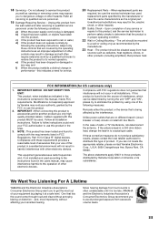
... recommended by Yamaha Corporation of radio or TV interference, relocate/reorient the antenna. This equipment generates/uses radio frequencies and, if not installed and used according to the instructions found to the operation of any way, and f) When the product exhibits a distinct change the lead-in the USA. 3. When replacement parts are on different branch (circuit breaker or fuse) circuits or install AC line filter/s. Unauthorized...
... recommended by Yamaha Corporation of radio or TV interference, relocate/reorient the antenna. This equipment generates/uses radio frequencies and, if not installed and used according to the instructions found to the operation of any way, and f) When the product exhibits a distinct change the lead-in the USA. 3. When replacement parts are on different branch (circuit breaker or fuse) circuits or install AC line filter/s. Unauthorized...
Owner's Manual
Page 4
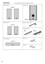
G Main speakers G Subwoofer G Rear speakers G Center speaker G Audio connection cable G Speaker cables [4m] [15m] X 3 X 2 G Fastener X 4 G Pads IV UNPACKING After unpacking, check that the following items are contained.
G Main speakers G Subwoofer G Rear speakers G Center speaker G Audio connection cable G Speaker cables [4m] [15m] X 3 X 2 G Fastener X 4 G Pads IV UNPACKING After unpacking, check that the following items are contained.
Owner's Manual
Page 5
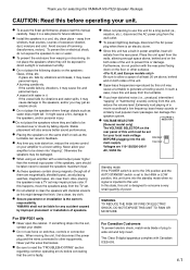
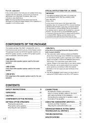
... of plug to consume a very small quantity of a movie soundtrack's low frequency, bass-heavy sounds or similarly loud popular music passages can result in feedback. ● Any time you for selecting this YAMAHA NS-P320 Speaker Package. E-1 near a TV set to clean the speakers with the rear panel facing down on the floor or other equipments. Use a clean, dry cloth. ● Secure placement or installation is set...
... of plug to consume a very small quantity of a movie soundtrack's low frequency, bass-heavy sounds or similarly loud popular music passages can result in feedback. ● Any time you for selecting this YAMAHA NS-P320 Speaker Package. E-1 near a TV set to clean the speakers with the rear panel facing down on the floor or other equipments. Use a clean, dry cloth. ● Secure placement or installation is set...
Owner's Manual
Page 6
... center speaker 4 Mounting the rear speakers 5 E-2 CONNECTIONS 6 An example of basic connections 6 How to connect speaker cables to the input and output terminals of the speakers 8 Connecting the subwoofer to speaker output terminals of the amplifier 9 USING THE SUBWOOFER (SW-P201) ........ 10 Controls and their functions 10 Adjusting the subwoofer before use in your existing audio system by connecting to either the speaker terminals or the line output (pin jack) terminals of the amplifier. ● The AUTO STANDBY switch saves you the trouble of setting the POWER switch...
... center speaker 4 Mounting the rear speakers 5 E-2 CONNECTIONS 6 An example of basic connections 6 How to connect speaker cables to the input and output terminals of the speakers 8 Connecting the subwoofer to speaker output terminals of the amplifier 9 USING THE SUBWOOFER (SW-P201) ........ 10 Controls and their functions 10 Adjusting the subwoofer before use in your existing audio system by connecting to either the speaker terminals or the line output (pin jack) terminals of the amplifier. ● The AUTO STANDBY switch saves you the trouble of setting the POWER switch...
Owner's Manual
Page 7
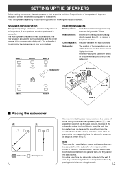
SETTING UP THE SPEAKERS Before making connections, place all speakers in the center of the subwoofer is for reinforcing low frequencies on your listening position, facing slightly inward. The main speakers are not highly directional. The rear speakers are used for center sounds (dialog etc.). Refer to place the subwoofer on your listening position by placing bookshelves etc. To prevent this system. Note There may be a case...
SETTING UP THE SPEAKERS Before making connections, place all speakers in the center of the subwoofer is for reinforcing low frequencies on your listening position, facing slightly inward. The main speakers are not highly directional. The rear speakers are used for center sounds (dialog etc.). Refer to place the subwoofer on your listening position by placing bookshelves etc. To prevent this system. Note There may be a case...
Owner's Manual
Page 8
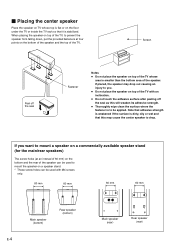
...at an interval of 60 mm) on top of the TV, to be applied. If placed, the speaker may cause the center speaker to mount a speaker on a commercially available speaker stand (for the main/rear speakers) The screw holes (at four points on the floor under the TV or inside the TV rack so...wipe clean the surface where the fastener is stabilized. If you . ● Do not place the speaker on top of the speaker can be used to mount the speaker on a speaker stand. * Those screw holes can be used with an inclination. ● Do not touch the adhesive surface after peeling off the seal Fastener ...
...at an interval of 60 mm) on top of the TV, to be applied. If placed, the speaker may cause the center speaker to mount a speaker on a commercially available speaker stand (for the main/rear speakers) The screw holes (at four points on the floor under the TV or inside the TV rack so...wipe clean the surface where the fastener is stabilized. If you . ● Do not place the speaker on top of the speaker can be used to mount the speaker on a speaker stand. * Those screw holes can be used with an inclination. ● Do not touch the adhesive surface after peeling off the seal Fastener ...

Owner's Manual
Page 9
... not install the speakers to mount the speaker so that the screws are securely caught by the narrow parts of the rear speakers to prevent the rear speakers from moving by 2 using the holes on the speakers' back panels Diam. 3.5 to 4 mm Min. 20 mm 6 mm Tapping screw (Available at the hardware store) Note It is recommended that you connect the speaker cables to the speaker...
... not install the speakers to mount the speaker so that the screws are securely caught by the narrow parts of the rear speakers to prevent the rear speakers from moving by 2 using the holes on the speakers' back panels Diam. 3.5 to 4 mm Min. 20 mm 6 mm Tapping screw (Available at the hardware store) Note It is recommended that you connect the speaker cables to the speaker...
Owner's Manual
Page 10
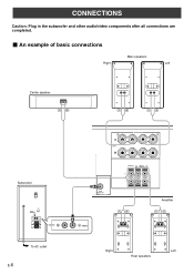
SUB WOOFER OUTPUT Amplifier /MONO Right Left Rear speakers CONNECTIONS Caution: Plug in the subwoofer and other audio/video components after all connections are completed. Ⅵ An example of basic connections Main speakers Right Left Center speaker Subwoofer POWER ON OFF VOLUME STANDBY-RED ON-GREEN AUTO STANDBY HIGH LOW OFF 0 I0 INPUT2 /MONO INPUT1 FROM AMPLIFIER OUTPUT TO SPEAKERS INPUT2 To AC outlet E-6 R+ A SPEAKERS - - +L MAIN B IMPEDA EO SET B MA CENTER REAR R (SURROUND) L CEN RE + MAIN A OR B: 4 M A + B: 8 M CENTER : 6 M REAR :6 M -
SUB WOOFER OUTPUT Amplifier /MONO Right Left Rear speakers CONNECTIONS Caution: Plug in the subwoofer and other audio/video components after all connections are completed. Ⅵ An example of basic connections Main speakers Right Left Center speaker Subwoofer POWER ON OFF VOLUME STANDBY-RED ON-GREEN AUTO STANDBY HIGH LOW OFF 0 I0 INPUT2 /MONO INPUT1 FROM AMPLIFIER OUTPUT TO SPEAKERS INPUT2 To AC outlet E-6 R+ A SPEAKERS - - +L MAIN B IMPEDA EO SET B MA CENTER REAR R (SURROUND) L CEN RE + MAIN A OR B: 4 M A + B: 8 M CENTER : 6 M REAR :6 M -
Owner's Manual
Page 11
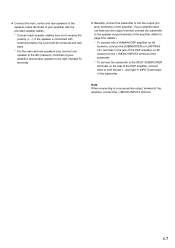
... details.) * To connect with the provided speaker cables. * Connect each speaker making sure not to the line output (pin jack) terminal(s) of the subwoofer. If your amplifier, and another speaker to the right (marked R) terminals. ● Basically, connect the subwoofer to reverse the polarity (+, -). E-7 If the speaker is connected with reversed polarity, the sound will be unnatural and lack bass. * For the main and rear speakers only, connect one speaker to the...
... details.) * To connect with the provided speaker cables. * Connect each speaker making sure not to the line output (pin jack) terminal(s) of the subwoofer. If your amplifier, and another speaker to the right (marked R) terminals. ● Basically, connect the subwoofer to reverse the polarity (+, -). E-7 If the speaker is connected with reversed polarity, the sound will be unnatural and lack bass. * For the main and rear speakers only, connect one speaker to the...
Owner's Manual
Page 12
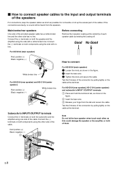
... bare speaker wires touch each speaker cable by pulling lightly on both components using the side with no line. For NS-E104 (rear speaker), NS-C104 (center speaker) and subwoofer's INPUT 1/OUTPUT terminals 1 Press and hold the terminal's tab, as shown in the figure. 2 Insert the bare wire. 3 Tighten the knob and secure the cable. Connect the (+) terminals on both the speaker and the amplifier using the other side has no sound will...
... bare speaker wires touch each speaker cable by pulling lightly on both components using the side with no line. For NS-E104 (rear speaker), NS-C104 (center speaker) and subwoofer's INPUT 1/OUTPUT terminals 1 Press and hold the terminal's tab, as shown in the figure. 2 Insert the bare wire. 3 Tighten the knob and secure the cable. Connect the (+) terminals on both the speaker and the amplifier using the other side has no sound will...
Owner's Manual
Page 13
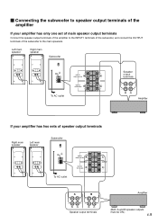
... INPUT1 FROM AMPLIFIER OUTPUT TO SPEAKERS To AC outlet INPUT1 FROM AMPLIFIER OUTPUT TO SPEAKERS A B Amplifier Speaker output terminals (Both A and B speaker outputs must be ON.) E-9 Left main speaker Right main speaker Subwoofer POWER ON OFF VOLUME STANDBY-RED ON-GREEN AUTO STANDBY HIGH LOW OFF 0 I0 INPUT2 /MONO INPUT1 FROM AMPLIFIER OUTPUT TO SPEAKERS INPUT1 FROM AMPLIFIER OUTPUT TO SPEAKERS Speaker output terminals To AC outlet Amplifier If your amplifier has only one set of main speaker output terminals Connect the speaker output terminals of...
... INPUT1 FROM AMPLIFIER OUTPUT TO SPEAKERS To AC outlet INPUT1 FROM AMPLIFIER OUTPUT TO SPEAKERS A B Amplifier Speaker output terminals (Both A and B speaker outputs must be ON.) E-9 Left main speaker Right main speaker Subwoofer POWER ON OFF VOLUME STANDBY-RED ON-GREEN AUTO STANDBY HIGH LOW OFF 0 I0 INPUT2 /MONO INPUT1 FROM AMPLIFIER OUTPUT TO SPEAKERS INPUT1 FROM AMPLIFIER OUTPUT TO SPEAKERS Speaker output terminals To AC outlet Amplifier If your amplifier has only one set of main speaker output terminals Connect the speaker output terminals of...
Owner's Manual
Page 14
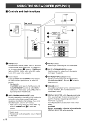
... the POWER switch lights up RED when no signal is inputted to the subwoofer. 3 AUTO STANDBY (HIGH/LOW/OFF) switch By setting this mode. USING THE SUBWOOFER (SW-P201) Ⅵ Controls and their functions VOLTAGE SELECTOR POWER ON 1 OFF Rear panel VOLTAGE SELECTOR POWER ON OFF 220V-240V 110V-120V VOLUME STANDBY-RED ON-GREEN AUTO STANDBY HIGH LOW OFF 0 I0 INPUT2 /MONO INPUT1 FROM AMPLIFIER OUTPUT TO SPEAKERS 220V-240V 110V-120V 8 VOLUME 2 3 4 STANDBY-RED ON-GREEN AUTO STANDBY HIGH...
... the POWER switch lights up RED when no signal is inputted to the subwoofer. 3 AUTO STANDBY (HIGH/LOW/OFF) switch By setting this mode. USING THE SUBWOOFER (SW-P201) Ⅵ Controls and their functions VOLTAGE SELECTOR POWER ON 1 OFF Rear panel VOLTAGE SELECTOR POWER ON OFF 220V-240V 110V-120V VOLUME STANDBY-RED ON-GREEN AUTO STANDBY HIGH LOW OFF 0 I0 INPUT2 /MONO INPUT1 FROM AMPLIFIER OUTPUT TO SPEAKERS 220V-240V 110V-120V 8 VOLUME 2 3 4 STANDBY-RED ON-GREEN AUTO STANDBY HIGH...
Owner's Manual
Page 15
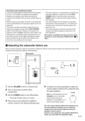
... using the amplifier's volume control. This function is available only when the power of the subwoofer is on even with a low level of your whole sound system by sensing audio signals input to the subwoofer. channel home theater system. 0 I0 Once the volume balance between ON and OFF manually. * This function detects the low-frequency components below . This function operates by setting the POWER switch (1) to "ON"). Ⅵ Adjusting the subwoofer before use the POWER switch...
... using the amplifier's volume control. This function is available only when the power of the subwoofer is on even with a low level of your whole sound system by sensing audio signals input to the subwoofer. channel home theater system. 0 I0 Once the volume balance between ON and OFF manually. * This function detects the low-frequency components below . This function operates by setting the POWER switch (1) to "ON"). Ⅵ Adjusting the subwoofer before use the POWER switch...
Owner's Manual
Page 16
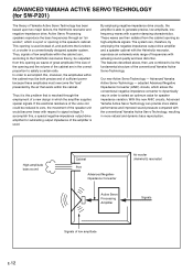
... negative-impedance drive. Our new Active Servo Technology - Active Servo Processing speakers reproduce the bass frequencies through the employment of the speaker unit would become linear with the Helmholtz resonator, reproduce an extremely wide range of sufficient power because these amplitudes must be the fundamental structure of the opening as waves of great amplitude if the size of the conventional Yamaha Active Servo...
... negative-impedance drive. Our new Active Servo Technology - Active Servo Processing speakers reproduce the bass frequencies through the employment of the speaker unit would become linear with the Helmholtz resonator, reproduce an extremely wide range of sufficient power because these amplitudes must be the fundamental structure of the opening as waves of great amplitude if the size of the conventional Yamaha Active Servo...
Owner's Manual
Page 17
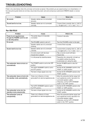
... is not listed below or if the instructions given below when this unit does not function properly. No sound. Sound level is too low. The subwoofer turns on automatically. Speaker cables are not connected correctly. A source sound with bass frequencies. The POWER switch is an influence of noise generated from external appliances etc. There is set the AUTO STANDBY switch to the "HIGH" position. along the walls. Set the AUTO STANDBY switch to the...
... is not listed below or if the instructions given below when this unit does not function properly. No sound. Sound level is too low. The subwoofer turns on automatically. Speaker cables are not connected correctly. A source sound with bass frequencies. The POWER switch is an influence of noise generated from external appliances etc. There is set the AUTO STANDBY switch to the "HIGH" position. along the walls. Set the AUTO STANDBY switch to the...
Owner's Manual
Page 18
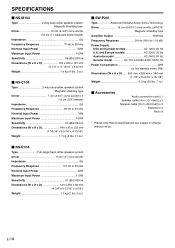
... standby mode: 6W) Dimensions (W x H x D) ...... 200 mm x 395 mm x 384 mm (7-7/8" x 15-9/16" x 15-1/8") Weight 9.3 kg (20 lbs. 7 oz.) Ⅵ Accessories Audio connection cord x 1 Speaker cable [4 m (13.1 feet)] x 3 Speaker cable [15 m (49.2 feet)] x 2 Fastener x 4 Pad x 8 * Please note that all specifications are subject to change without notice. Ⅵ NS-E104 Type Full-range bass-reflex speaker system Driver 10 cm (4") cone woofer Impedance 6Ω Frequency Response 110 Hz to 20 kHz Nominal Input Power 70W Maximum Input Power...
... standby mode: 6W) Dimensions (W x H x D) ...... 200 mm x 395 mm x 384 mm (7-7/8" x 15-9/16" x 15-1/8") Weight 9.3 kg (20 lbs. 7 oz.) Ⅵ Accessories Audio connection cord x 1 Speaker cable [4 m (13.1 feet)] x 3 Speaker cable [15 m (49.2 feet)] x 2 Fastener x 4 Pad x 8 * Please note that all specifications are subject to change without notice. Ⅵ NS-E104 Type Full-range bass-reflex speaker system Driver 10 cm (4") cone woofer Impedance 6Ω Frequency Response 110 Hz to 20 kHz Nominal Input Power 70W Maximum Input Power...

Owner's Manual
Page 19
...-BEAUBOURG 77312 MARNE-LA-VALLEE CEDEX02, FRANCE YAMAHA ELECTRONICS (UK) LTD. YAMAHA ELECTRONICS CORPORATION, USA 6660 ORANGETHORPE AVE., BUENA PARK, CALIF. 90620, U.S.A. YAMAHA HOUSE, 200 RICKMANSWORTH ROAD WATFORD, HERTS WD1 7JS, ENGLAND YAMAHA SCANDINAVIA A.B. OF GERMANY YAMAHA ELECTRONIQUE FRANCE S.A. J A WETTERGRENS GATA 1, BOX 30053, 400 43 VASTRA FRÖLUNDA, SWEDEN YAMAHA MUSIC AUSTRALIA PTY, LTD. 17-33 MARKET...
...-BEAUBOURG 77312 MARNE-LA-VALLEE CEDEX02, FRANCE YAMAHA ELECTRONICS (UK) LTD. YAMAHA ELECTRONICS CORPORATION, USA 6660 ORANGETHORPE AVE., BUENA PARK, CALIF. 90620, U.S.A. YAMAHA HOUSE, 200 RICKMANSWORTH ROAD WATFORD, HERTS WD1 7JS, ENGLAND YAMAHA SCANDINAVIA A.B. OF GERMANY YAMAHA ELECTRONIQUE FRANCE S.A. J A WETTERGRENS GATA 1, BOX 30053, 400 43 VASTRA FRÖLUNDA, SWEDEN YAMAHA MUSIC AUSTRALIA PTY, LTD. 17-33 MARKET...


