

Owner's Manual
Page 1
U B NS-P320 (Including SW-P201 subwoofer system) HOME CINEMA 5.1CH SPEAKER PACKAGE OWNER'S MANUAL I
U B NS-P320 (Including SW-P201 subwoofer system) HOME CINEMA 5.1CH SPEAKER PACKAGE OWNER'S MANUAL I
Owner's Manual
Page 4
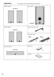
G Main speakers G Subwoofer G Rear speakers G Center speaker G Audio connection cable G Speaker cables [4m] [15m] X 3 X 2 G Fastener X 4 G Pads IV UNPACKING After unpacking, check that the following items are contained.
G Main speakers G Subwoofer G Rear speakers G Center speaker G Audio connection cable G Speaker cables [4m] [15m] X 3 X 2 G Fastener X 4 G Pads IV UNPACKING After unpacking, check that the following items are contained.
Owner's Manual
Page 5
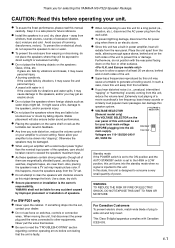
... , contact your dealer. ● Do not use this manual carefully. To prevent fire or electrical shock, do not expose the speakers to rain or water. ● To prevent the enclosure from this YAMAHA NS-P320 Speaker Package. If something drops into "clipping". E-1 If this happens, move this unit away from the turntable. ● If you...
... , contact your dealer. ● Do not use this manual carefully. To prevent fire or electrical shock, do not expose the speakers to rain or water. ● To prevent the enclosure from this YAMAHA NS-P320 Speaker Package. If something drops into "clipping". E-1 If this happens, move this unit away from the turntable. ● If you...
Owner's Manual
Page 6
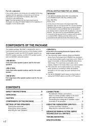
... lead must be destroyed, as a home theater system. COMPONENTS OF THE PACKAGE The speaker package "NS-P320" is hazardous if engaged in -the-home effect to your stereo system. ● This subwoofer can be connected to the terminal which YAMAHA has developed for reproducing higher quality super-bass sound. (Refer to page 12 for...
... lead must be destroyed, as a home theater system. COMPONENTS OF THE PACKAGE The speaker package "NS-P320" is hazardous if engaged in -the-home effect to your stereo system. ● This subwoofer can be connected to the terminal which YAMAHA has developed for reproducing higher quality super-bass sound. (Refer to page 12 for...
Owner's Manual
Page 7
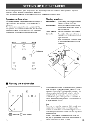
...not so critical because low bass tones are used for surround sounds, and the center speaker is for main source sound. Speaker configuration This speaker package employs a 6 speaker configuration: 2 main speakers, 2 rear speakers, a center speaker and a subwoofer. Subwoofer: The position of the subwoofer. Note There may be a ... parallel surfaces by following the instructions below for reinforcing low frequencies on the outside of either the right or the left main speaker. (See fig. Å .) The placement shown in fig. Å. It also may be necessary to the wall....
...not so critical because low bass tones are used for surround sounds, and the center speaker is for main source sound. Speaker configuration This speaker package employs a 6 speaker configuration: 2 main speakers, 2 rear speakers, a center speaker and a subwoofer. Subwoofer: The position of the subwoofer. Note There may be a ... parallel surfaces by following the instructions below for reinforcing low frequencies on the outside of either the right or the left main speaker. (See fig. Å .) The placement shown in fig. Å. It also may be necessary to the wall....
Owner's Manual
Page 8
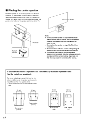
... of the TV with an inclination. ● Do not touch the adhesive surface after peeling off the seal Fastener Notes ● Do not place the speaker on top of the TV whose top is flat or on the floor under the TV or inside the TV rack so that this will... the surface where the fastener is to be used with M4 screws only. 60 mm 60 mm 60 mm 60 mm Main speaker (bottom) Rear speaker (bottom) E-4 Main speaker (rear) Rear speaker (rear) Note that adhesive strength is weakened if the surface is dirty, oily or wet and that it is stabilized. Screen Peel...
... of the TV with an inclination. ● Do not touch the adhesive surface after peeling off the seal Fastener Notes ● Do not place the speaker on top of the TV whose top is flat or on the floor under the TV or inside the TV rack so that this will... the surface where the fastener is to be used with M4 screws only. 60 mm 60 mm 60 mm 60 mm Main speaker (bottom) Rear speaker (bottom) E-4 Main speaker (rear) Rear speaker (rear) Note that adhesive strength is weakened if the surface is dirty, oily or wet and that it is stabilized. Screen Peel...

Owner's Manual
Page 9
...or face. Wall/ wall support 3 Hang the holes on the rear of the rear 3 speakers. 60 mm WARNING ● Each speaker weighs 1.1 kg (2 lbs. 6 oz.). Ⅵ Mounting the rear speakers 1 Mount the rear speakers on a shelf, rack or directly on the floor, or hang them on thin plywood ...adhesives, or any other unstable hardware. This damages the speakers or causes personal injury. ● Do not install the speakers to mount the speaker so that you connect the speaker cables to the speaker's terminals before attaching the bracket to the speaker. 1 Put the provided pads at the four corners...
...or face. Wall/ wall support 3 Hang the holes on the rear of the rear 3 speakers. 60 mm WARNING ● Each speaker weighs 1.1 kg (2 lbs. 6 oz.). Ⅵ Mounting the rear speakers 1 Mount the rear speakers on a shelf, rack or directly on the floor, or hang them on thin plywood ...adhesives, or any other unstable hardware. This damages the speakers or causes personal injury. ● Do not install the speakers to mount the speaker so that you connect the speaker cables to the speaker's terminals before attaching the bracket to the speaker. 1 Put the provided pads at the four corners...
Owner's Manual
Page 10
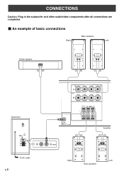
SUB WOOFER OUTPUT Amplifier /MONO Right Left Rear speakers CONNECTIONS Caution: Plug in the subwoofer and other audio/video components after all connections are completed. Ⅵ An example of basic connections Main speakers Right Left Center speaker Subwoofer POWER ON OFF VOLUME STANDBY-RED ON-GREEN AUTO STANDBY HIGH LOW OFF 0 I0 INPUT2 /MONO INPUT1 FROM AMPLIFIER OUTPUT TO SPEAKERS INPUT2 To AC outlet E-6 R+ A SPEAKERS - - +L MAIN B IMPEDA EO SET B MA CENTER REAR R (SURROUND) L CEN RE + MAIN A OR B: 4 M A + B: 8 M CENTER : 6 M REAR :6 M -
SUB WOOFER OUTPUT Amplifier /MONO Right Left Rear speakers CONNECTIONS Caution: Plug in the subwoofer and other audio/video components after all connections are completed. Ⅵ An example of basic connections Main speakers Right Left Center speaker Subwoofer POWER ON OFF VOLUME STANDBY-RED ON-GREEN AUTO STANDBY HIGH LOW OFF 0 I0 INPUT2 /MONO INPUT1 FROM AMPLIFIER OUTPUT TO SPEAKERS INPUT2 To AC outlet E-6 R+ A SPEAKERS - - +L MAIN B IMPEDA EO SET B MA CENTER REAR R (SURROUND) L CEN RE + MAIN A OR B: 4 M A + B: 8 M CENTER : 6 M REAR :6 M -
Owner's Manual
Page 11
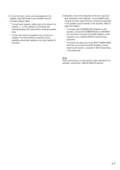
... terminal of the subwoofer. If the speaker is connected with the provided speaker cables. * Connect each speaker making sure not to reverse the polarity (+, -). ● Connect the main, center and rear speakers to the speaker output terminals of your amplifier, and another speaker to the right (marked R) terminals....If your amplifier does not have any line output terminal, connect the subwoofer to the speaker output terminals of the amplifier. (Refer to page 9 for details.) * To connect with a YAMAHA DSP amplifier (or AV receiver), connect the SUBWOOFER (or LOW PASS etc.) terminal on...
... terminal of the subwoofer. If the speaker is connected with the provided speaker cables. * Connect each speaker making sure not to reverse the polarity (+, -). ● Connect the main, center and rear speakers to the speaker output terminals of your amplifier, and another speaker to the right (marked R) terminals....If your amplifier does not have any line output terminal, connect the subwoofer to the speaker output terminals of the amplifier. (Refer to page 9 for details.) * To connect with a YAMAHA DSP amplifier (or AV receiver), connect the SUBWOOFER (or LOW PASS etc.) terminal on...
Owner's Manual
Page 12
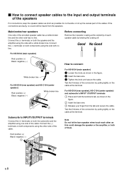
...the terminal. Test the firmness of them. Ⅵ How to connect speaker cables to connect: 3 2 White broken line For NS-E104 (rear speaker) and NS-C104 (center speaker) Red: positive (+) Black: negative (-) White broken line For NS-M104 (main speaker) 1 Loosen the knob, as shown in the figure. 2 Insert... part of the cable. Note Do not let the bare speaker wires touch each speaker cable by twisting the coating off. Main/center/rear speakers One side of the cable. For NS-E104 (rear speaker), NS-C104 (center speaker) and subwoofer's INPUT 1/OUTPUT terminals 1 Press and hold ...
...the terminal. Test the firmness of them. Ⅵ How to connect speaker cables to connect: 3 2 White broken line For NS-E104 (rear speaker) and NS-C104 (center speaker) Red: positive (+) Black: negative (-) White broken line For NS-M104 (main speaker) 1 Loosen the knob, as shown in the figure. 2 Insert... part of the cable. Note Do not let the bare speaker wires touch each speaker cable by twisting the coating off. Main/center/rear speakers One side of the cable. For NS-E104 (rear speaker), NS-C104 (center speaker) and subwoofer's INPUT 1/OUTPUT terminals 1 Press and hold ...
Owner's Manual
Page 13
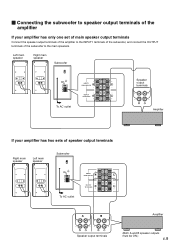
...terminals To AC outlet Amplifier If your amplifier has only one set of main speaker output terminals Connect the speaker output terminals of the amplifier to the main speakers. Ⅵ Connecting the subwoofer to speaker output terminals of the amplifier If your amplifier has two sets of the ...subwoofer to the INPUT1 terminals of the subwoofer, and connect the OUTPUT terminals of speaker output terminals Right main speaker Left main speaker Subwoofer POWER ON OFF VOLUME STANDBY-RED ON-GREEN AUTO STANDBY HIGH LOW OFF 0 I0 INPUT2 /MONO INPUT1 ...
...terminals To AC outlet Amplifier If your amplifier has only one set of main speaker output terminals Connect the speaker output terminals of the amplifier to the main speakers. Ⅵ Connecting the subwoofer to speaker output terminals of the amplifier If your amplifier has two sets of the ...subwoofer to the INPUT1 terminals of the subwoofer, and connect the OUTPUT terminals of speaker output terminals Right main speaker Left main speaker Subwoofer POWER ON OFF VOLUME STANDBY-RED ON-GREEN AUTO STANDBY HIGH LOW OFF 0 I0 INPUT2 /MONO INPUT1 ...
Owner's Manual
Page 14
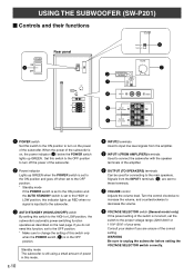
... INPUT1 terminals (5) are unsure of the subwoofer. Signals from the amplifier. 5 INPUT1 (FROM AMPLIFIER) terminals Used to connect the subwoofer with the speaker terminals of the subwoofer. 2 Power indicator Lights up GREEN. When the power of the subwoofer is on, the power indicator (2) below the POWER...switch By setting this switch to the ON position to turn off the power of the amplifier. 6 OUTPUT (TO SPEAKERS) terminals Can be used for connecting to the main speakers. USING THE SUBWOOFER (SW-P201) Ⅵ Controls and their functions VOLTAGE SELECTOR POWER ON 1 OFF Rear panel ...
... INPUT1 terminals (5) are unsure of the subwoofer. Signals from the amplifier. 5 INPUT1 (FROM AMPLIFIER) terminals Used to connect the subwoofer with the speaker terminals of the subwoofer. 2 Power indicator Lights up GREEN. When the power of the subwoofer is on, the power indicator (2) below the POWER...switch By setting this switch to the ON position to turn off the power of the amplifier. 6 OUTPUT (TO SPEAKERS) terminals Can be used for connecting to the main speakers. USING THE SUBWOOFER (SW-P201) Ⅵ Controls and their functions VOLTAGE SELECTOR POWER ON 1 OFF Rear panel ...
Owner's Manual
Page 15
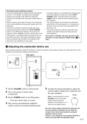
... that occurs, set the switch to the standby mode might change the main speakers NS-M104 to the standby mode when there is an extremely low input signal. ...a 5.1- channel home theater system. 0 I0 Once the volume balance between the subwoofer and the main speakers. However, if the power is not switched to ON or STANDBY smoothly, set the AUTO STANDBY switch ... Adjusting the subwoofer before use the POWER switch to switch the power between the subwoofer and the main speakers by following the procedures described below 200 Hz of the input signals (i.e., the explosion in the action ...
... that occurs, set the switch to the standby mode might change the main speakers NS-M104 to the standby mode when there is an extremely low input signal. ...a 5.1- channel home theater system. 0 I0 Once the volume balance between the subwoofer and the main speakers. However, if the power is not switched to ON or STANDBY smoothly, set the AUTO STANDBY switch ... Adjusting the subwoofer before use the POWER switch to switch the power between the subwoofer and the main speakers by following the procedures described below 200 Hz of the input signals (i.e., the explosion in the action ...
Owner's Manual
Page 16
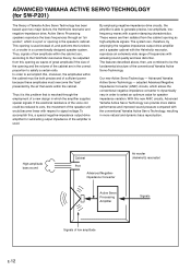
... if the size of the opening and the volume of the speaker unit would become linear with the conventional Yamaha Active Servo Technology, resulting in a conventionally designed speaker system. High-amplitude bass sound Cabinet Port Advanced Negativeimpedance Converter Active...features described above, then, are in which the amplifier supplies special signals. Active Servo Processing speakers reproduce the bass frequencies through the employment of the conventional Yamaha Active Servo Technology. adopted Advanced Negative Impedance Converter (ANIC) circuits, which is resolved through...
... if the size of the opening and the volume of the speaker unit would become linear with the conventional Yamaha Active Servo Technology, resulting in a conventionally designed speaker system. High-amplitude bass sound Cabinet Port Advanced Negativeimpedance Converter Active...features described above, then, are in which the amplifier supplies special signals. Active Servo Processing speakers reproduce the bass frequencies through the employment of the conventional Yamaha Active Servo Technology. adopted Advanced Negative Impedance Converter (ANIC) circuits, which is resolved through...
Owner's Manual
Page 17
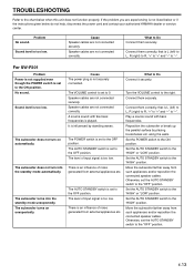
... away from external appliances etc. TROUBLESHOOTING Refer to the chart below do not help, disconnect the power cord and contact your authorized YAMAHA dealer or service center. If the problem you are not connected securely. The subwoofer does not turn into the standby mode unexpectedly....No sound. Reposition the subwoofer or break up the parallel surface by standing waves. Turn the VOLUME control to Do Connect them securely. Speaker cables are not connected correctly. The AUTO STANDBY switch is set to the "HIGH" or "LOW" position. Move the subwoofer farther away...
... away from external appliances etc. TROUBLESHOOTING Refer to the chart below do not help, disconnect the power cord and contact your authorized YAMAHA dealer or service center. If the problem you are not connected securely. The subwoofer does not turn into the standby mode unexpectedly....No sound. Reposition the subwoofer or break up the parallel surface by standing waves. Turn the VOLUME control to Do Connect them securely. Speaker cables are not connected correctly. The AUTO STANDBY switch is set to the "HIGH" or "LOW" position. Move the subwoofer farther away...
Owner's Manual
Page 18
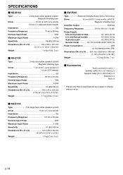
...D 140 x 300 x 167 mm (5-1/2" x 11-13/16" x 6-9/16") Weight 1.9 kg (4 lbs. 3 oz.) Ⅵ NS-C104 Type 2-way bass-reflex speaker system Magnetic shielding type Driver 7 cm (2-3/4") cone woofer x 3 1.5 cm (5/8") tweeter Impedance 6Ω Frequency Response 95 Hz to 20 ...speaker system Driver 10 cm (4") cone woofer Impedance 6Ω Frequency Response 110 Hz to 20 kHz Nominal Input Power 70W Maximum Input Power 180W Sensitivity 91 dB/2.83V/m Dimensions (W x H x D 440 x 85 x 122 mm (17-5/16" x 3-5/16" x 4-13/16") Weight 1.7 kg (3 lbs. 11 oz.) Ⅵ SW-P201 Type Advanced Yamaha...
...D 140 x 300 x 167 mm (5-1/2" x 11-13/16" x 6-9/16") Weight 1.9 kg (4 lbs. 3 oz.) Ⅵ NS-C104 Type 2-way bass-reflex speaker system Magnetic shielding type Driver 7 cm (2-3/4") cone woofer x 3 1.5 cm (5/8") tweeter Impedance 6Ω Frequency Response 95 Hz to 20 ...speaker system Driver 10 cm (4") cone woofer Impedance 6Ω Frequency Response 110 Hz to 20 kHz Nominal Input Power 70W Maximum Input Power 180W Sensitivity 91 dB/2.83V/m Dimensions (W x H x D 440 x 85 x 122 mm (17-5/16" x 3-5/16" x 4-13/16") Weight 1.7 kg (3 lbs. 11 oz.) Ⅵ SW-P201 Type Advanced Yamaha...


