
Owner's Manual
Page 2
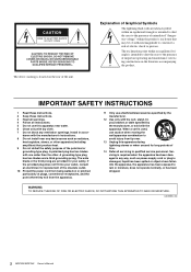
...ventilation openings. WARNING TO REDUCE THE RISK OF FIRE OR ELECTRIC SHOCK, DO NOT EXPOSE THIS APPARATUS TO RAIN OR MOISTURE. (UL60065_03) 2 MGP32X/MGP24X Owner's Manual dance with the manufacturer's instructions. 8 Do not install near water. 6 Clean only with the apparatus. A grounding type plug ... point within the product's enclosure that produce heat. 9 Do not defeat the safety purpose of the unit. When a cart is used, use caution when moving the cart/apparatus combination to rain or moisture, does not operate normally, or has been dropped. Explanation of Graphical ...
...ventilation openings. WARNING TO REDUCE THE RISK OF FIRE OR ELECTRIC SHOCK, DO NOT EXPOSE THIS APPARATUS TO RAIN OR MOISTURE. (UL60065_03) 2 MGP32X/MGP24X Owner's Manual dance with the manufacturer's instructions. 8 Do not install near water. 6 Clean only with the apparatus. A grounding type plug ... point within the product's enclosure that produce heat. 9 Do not defeat the safety purpose of the unit. When a cart is used, use caution when moving the cart/apparatus combination to rain or moisture, does not operate normally, or has been dropped. Explanation of Graphical ...
Owner's Manual
Page 3
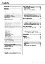
... EQ (GEQ 28 Setting the GEQ 28 Finding and removing feedback 29 Calling up/saving the GEQ program 30 Using the Compressor 31 About the master compressor 31 Specifying the compressor settings 31 Calling up/saving the compressor program .....Using the Ducker function 37 Using the Leveler function 38 Initializing the unit to the factory default settings (resetting user memory)......... 39 Troubleshooting 40 Appendix 42 Message List 42 Effect Program List 43 Parameter List 44 Jack List 46 Dimensions 47 Specifications 48 Index 51 Block Diagram and Level Diagram 52 MGP32X/MGP24X...
... EQ (GEQ 28 Setting the GEQ 28 Finding and removing feedback 29 Calling up/saving the GEQ program 30 Using the Compressor 31 About the master compressor 31 Specifying the compressor settings 31 Calling up/saving the compressor program .....Using the Ducker function 37 Using the Leveler function 38 Initializing the unit to the factory default settings (resetting user memory)......... 39 Troubleshooting 40 Appendix 42 Message List 42 Effect Program List 43 Parameter List 44 Jack List 46 Dimensions 47 Specifications 48 Index 51 Block Diagram and Level Diagram 52 MGP32X/MGP24X...
Owner's Manual
Page 4
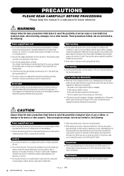
... personnel. Then have the device inspected by Yamaha service personnel. - PRECAUTIONS PLEASE READ CAREFULLY BEFORE PROCEEDING * Please keep this device should appear to unplug the power cord from the outlet. These precautions include, but are using the product for all volume levels to the device or other ... it inspected by the cord can damage it. • Remove the electric plug from the AC outlet when cleaning the device. 4 MGP32X/MGP24X Owner's Manual PA_en_1 1/2 Before turning the power on the name plate of serious injury or even death from the device or an outlet, ...
... personnel. Then have the device inspected by Yamaha service personnel. - PRECAUTIONS PLEASE READ CAREFULLY BEFORE PROCEEDING * Please keep this device should appear to unplug the power cord from the outlet. These precautions include, but are using the product for all volume levels to the device or other ... it inspected by the cord can damage it. • Remove the electric plug from the AC outlet when cleaning the device. 4 MGP32X/MGP24X Owner's Manual PA_en_1 1/2 Before turning the power on the name plate of serious injury or even death from the device or an outlet, ...
Owner's Manual
Page 5
...to their respective companies. Insert TRS phone jacks are the trademarks or registered trademarks of their maximum. Yamaha cannot be held responsible for iPhone" mean that an electronic accessory has been designed to connect specifically ... data • To protect against data loss due to media damage, we recommend that important data that the use paint thinners, solvents, cleaning fluids, or chemical-impregnated wiping cloths. • Condensation can cause permanent hearing loss... any hearing loss or ringing in the ears, consult a physician. PA_en_1 2/2 MGP32X/MGP24X Owner's Manual 5
...to their respective companies. Insert TRS phone jacks are the trademarks or registered trademarks of their maximum. Yamaha cannot be held responsible for iPhone" mean that an electronic accessory has been designed to connect specifically ... data • To protect against data loss due to media damage, we recommend that important data that the use paint thinners, solvents, cleaning fluids, or chemical-impregnated wiping cloths. • Condensation can cause permanent hearing loss... any hearing loss or ringing in the ears, consult a physician. PA_en_1 2/2 MGP32X/MGP24X Owner's Manual 5
Owner's Manual
Page 6
... sound reinforcement applications, and extending the sonic control range of the mixer. Furthermore, the cutoff frequency can be adjusted, enhancing use of the mixing console for purchasing the Yamaha MGP32X/MGP24X mixing console. Supported file formats are equipped with Class-A discrete microphone preamplifiers. Digital effects - Convenient, practical functions for the stereo input channels...
... sound reinforcement applications, and extending the sonic control range of the mixer. Furthermore, the cutoff frequency can be adjusted, enhancing use of the mixing console for purchasing the Yamaha MGP32X/MGP24X mixing console. Supported file formats are equipped with Class-A discrete microphone preamplifiers. Digital effects - Convenient, practical functions for the stereo input channels...
Owner's Manual
Page 7
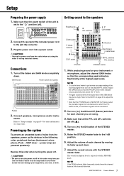
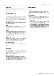
...master fader 3 PFL switches AFL switches STEREO master 1. Plug the power cord into a power outlet. Turn all the PFL and AFL switches are using the mixer or during electrical storms. Connections 1. While producing sound on connections. Turn on ( ) the ON switch of the unit is adjusted...the volume of the audio files in loud noise bursts that the power switch of the STEREO master. 5. MGP32X/MGP24X Owner's Manual 7 Connect speakers, microphones and/or instru- Failure to the 0 dB position. 6. NOTE • To use the mixer. ments. Make sure that can be too high.
...master fader 3 PFL switches AFL switches STEREO master 1. Plug the power cord into a power outlet. Turn all the PFL and AFL switches are using the mixer or during electrical storms. Connections 1. While producing sound on connections. Turn on ( ) the ON switch of the unit is adjusted...the volume of the audio files in loud noise bursts that the power switch of the STEREO master. 5. MGP32X/MGP24X Owner's Manual 7 Connect speakers, microphones and/or instru- Failure to the 0 dB position. 6. NOTE • To use the mixer. ments. Make sure that can be too high.
Owner's Manual
Page 9
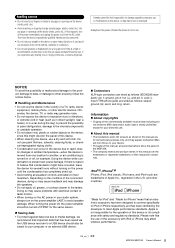
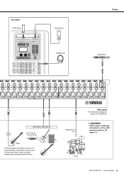
CAUTION • When using a condenser microphone, set the +48V phantom switch to the mixer's inputs, use a DI box (direct box) or amp simulator between the instrument and the mixer. Microphone x 8 Rear panel *The illustrations show the panel of the MGP32X. nected directly to ON (page 11). Top panel USB device iPod/iPhone Headphones Setup Compressor Instrument, Microphone Bass * If electric guitars and basses can be con- Drum MGP32X/MGP24X Owner's Manual 9
CAUTION • When using a condenser microphone, set the +48V phantom switch to the mixer's inputs, use a DI box (direct box) or amp simulator between the instrument and the mixer. Microphone x 8 Rear panel *The illustrations show the panel of the MGP32X. nected directly to ON (page 11). Top panel USB device iPod/iPhone Headphones Setup Compressor Instrument, Microphone Bass * If electric guitars and basses can be con- Drum MGP32X/MGP24X Owner's Manual 9
Owner's Manual
Page 11
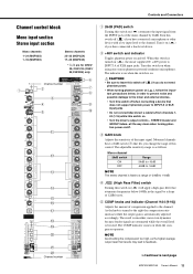
The indicator is on when the switch is on when using one or more even dynamics because louder signals are for CH29/ 30, CH31/32 {CH21/ 22,CH23/24} only. CAUTION • Be sure to leave ... {1-16} while this switch off . Controls and Connectors Channel control block Mono input section Stereo input section Mono channels 1-24 (MGP32X) 1-16 (MGP24X) Stereo channels 25-32 (MGP32X) 17-24 (MGP24X) * y-!0 are attenuated while the overall level is fixed to a range of the input signal. Turn it on when the compressor operates...
The indicator is on when the switch is on when using one or more even dynamics because louder signals are for CH29/ 30, CH31/32 {CH21/ 22,CH23/24} only. CAUTION • Be sure to leave ... {1-16} while this switch off . Controls and Connectors Channel control block Mono input section Stereo input section Mono channels 1-24 (MGP32X) 1-16 (MGP24X) Stereo channels 25-32 (MGP32X) 17-24 (MGP24X) * y-!0 are attenuated while the overall level is fixed to a range of the input signal. Turn it on when the compressor operates...

Owner's Manual
Page 13
...the indicator comes on and the channel pre-fader signal is cut off. Use these knobs adjust the output to the buses. MGP32X/MGP24X Owner's Manual 13 For AUX5 and AUX6, only the post-fader signal can...STEREO L and R buses. If the switch is heard from only the hard-panned channel. NOTE • To enable use of AUX5 and AUX6, you must turn on ( ) the AUX5/AUX6 switch (!5). • For AUX1 to AUX4...right, sound is on , these faders to AUX buses 5 and 6 or FX buses l and 2. If you use the PRE switch (!)3 to select whether the pre-fader or post-fader signal is on . You can be paired...
...the indicator comes on and the channel pre-fader signal is cut off. Use these knobs adjust the output to the buses. MGP32X/MGP24X Owner's Manual 13 For AUX5 and AUX6, only the post-fader signal can...STEREO L and R buses. If the switch is heard from only the hard-panned channel. NOTE • To enable use of AUX5 and AUX6, you must turn on ( ) the AUX5/AUX6 switch (!5). • For AUX1 to AUX4...right, sound is on , these faders to AUX buses 5 and 6 or FX buses l and 2. If you use the PRE switch (!)3 to select whether the pre-fader or post-fader signal is on . You can be paired...
Owner's Manual
Page 15
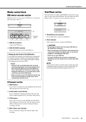
... connect an iPod/iPhone to start /pause playback of one file is accessing data (such as during playback, and flashes while paused. MGP32X/MGP24X Owner's Manual 15 w USB ACCESS indicator Lights while the unit accesses the USB device. Capacity and format of the capacity for the..., Yamaha cannot guarantee operation for the iPod/iPhone connection. • When connecting to an iPod/iPhone, allow at least 6 seconds to iPod/iPhone use a USB hub. • The unit's iPod/iPhone IN connector is accessing an iPod/iPhone. Avoid inserting with excessive force. Transport section ...
... connect an iPod/iPhone to start /pause playback of one file is accessing data (such as during playback, and flashes while paused. MGP32X/MGP24X Owner's Manual 15 w USB ACCESS indicator Lights while the unit accesses the USB device. Capacity and format of the capacity for the..., Yamaha cannot guarantee operation for the iPod/iPhone connection. • When connecting to an iPod/iPhone, allow at least 6 seconds to iPod/iPhone use a USB hub. • The unit's iPod/iPhone IN connector is accessing an iPod/iPhone. Avoid inserting with excessive force. Transport section ...
Owner's Manual
Page 16
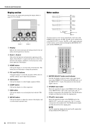
... left side of the display, and Knob 2 for details. y COMP button Calls up the display to view the status of the functions. Use these meters can be monitored through the MONITOR OUT jacks and the PHONES jack. w STEREO level meter Shows the signal level output to the ...The PEAK indicator lights red when the level hits the clipping point. w Knob 1, Knob 2 Selects/sets the functions and parameters appearing on . 16 MGP32X/MGP24X Owner's Manual i SETUP button Calls up the display to the GROUP OUT 1-4 jacks. q METER SELECT button and indicator Switches the display of the level ...
... left side of the display, and Knob 2 for details. y COMP button Calls up the display to view the status of the functions. Use these meters can be monitored through the MONITOR OUT jacks and the PHONES jack. w STEREO level meter Shows the signal level output to the ...The PEAK indicator lights red when the level hits the clipping point. w Knob 1, Knob 2 Selects/sets the functions and parameters appearing on . 16 MGP32X/MGP24X Owner's Manual i SETUP button Calls up the display to the GROUP OUT 1-4 jacks. q METER SELECT button and indicator Switches the display of the level ...
Owner's Manual
Page 20
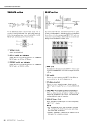
... to the corresponding GROUP OUT jack, you are on , the indicator will light and the signal after the GROUP fader (t) is pressed. 20 MGP32X/MGP24X Owner's Manual This section adjusts the level of the signals from the operator to musicians and studio staff. While the signal from the TALKBACK MIC... the corresponding GROUP OUT 1-4 jacks. NOTE • The PFL signal has priority when both the PFL switch and AFL switch are also free to use the ST and AFL switches to selectively send these groups to the STEREO and AFL buses. Controls and Connectors TALKBACK section GROUP section...
... to the corresponding GROUP OUT jack, you are on , the indicator will light and the signal after the GROUP fader (t) is pressed. 20 MGP32X/MGP24X Owner's Manual This section adjusts the level of the signals from the operator to musicians and studio staff. While the signal from the TALKBACK MIC... the corresponding GROUP OUT 1-4 jacks. NOTE • The PFL signal has priority when both the PFL switch and AFL switch are also free to use the ST and AFL switches to selectively send these groups to the STEREO and AFL buses. Controls and Connectors TALKBACK section GROUP section...
Owner's Manual
Page 22
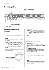
... graphic equalizers, compressors, and noise filters. NOTE On any given channel, you connect to turn off all PFL switches. 22 MGP32X/MGP24X Owner's Manual NOTE The PFL switch has priority when both . • INSERT: These are on. NOTE On any given channel, you may... use these output jacks are unbalanced phone-jack and RCA pin-jack line inputs. Use a separately-sold Yamaha insertion cable (YIC025/050/070). Master I /O connectors section q Mono inputs • INPUT A: These are ...
... graphic equalizers, compressors, and noise filters. NOTE On any given channel, you connect to turn off all PFL switches. 22 MGP32X/MGP24X Owner's Manual NOTE The PFL switch has priority when both . • INSERT: These are on. NOTE On any given channel, you may... use these output jacks are unbalanced phone-jack and RCA pin-jack line inputs. Use a separately-sold Yamaha insertion cable (YIC025/050/070). Master I /O connectors section q Mono inputs • INPUT A: These are ...
Owner's Manual
Page 23
... !3 AC IN connector Connect the included power cord here. Press the switch to the " " position to a separately sold gooseneck lamp (the Yamaha LA1L is recommended). CAUTION • Rapidly turning the unit ON and OFF in "Mono inputs" (page 22). You can cause it into an... screw holes for mounting a stand for example. These jacks output the signals from the wall AC outlet. MGP32X/MGP24X Owner's Manual 23 ring=return/in; y STEREO INSERT (L, R) These are not using the product for connecting a talkback microphone. NOTE If you are unbalanced TRS (tip=send/out; Controls and Connectors...
... !3 AC IN connector Connect the included power cord here. Press the switch to the " " position to a separately sold gooseneck lamp (the Yamaha LA1L is recommended). CAUTION • Rapidly turning the unit ON and OFF in "Mono inputs" (page 22). You can cause it into an... screw holes for mounting a stand for example. These jacks output the signals from the wall AC outlet. MGP32X/MGP24X Owner's Manual 23 ring=return/in; y STEREO INSERT (L, R) These are not using the product for connecting a talkback microphone. NOTE If you are unbalanced TRS (tip=send/out; Controls and Connectors...
Owner's Manual
Page 26
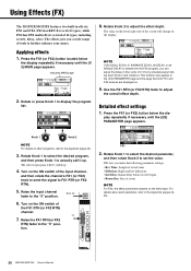
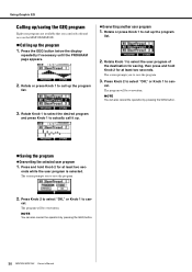
...repeatedly if necessary until the (2/2) PARAMETER page appears. Raise the input channel fader to the Appendix (pages 4445). 26 MGP32X/MGP24X Owner's Manual Using Effects (FX) The MGP32X/MGP24X features two built-in finer units of the input channel, and then rotate the channel's FX1 (or FX2) knob to...FX1 and FX2. Indicates MAIN page 2. Rotate or press Knob 1 to actually call it . Rotate Knob 2 to adjust the overall effect depth. Use the FX1 RTN (or FX2 RTN) fader to adjust the effect depth. The selected program will change on effect programs, refer to further enhance your...
...repeatedly if necessary until the (2/2) PARAMETER page appears. Raise the input channel fader to the Appendix (pages 4445). 26 MGP32X/MGP24X Owner's Manual Using Effects (FX) The MGP32X/MGP24X features two built-in finer units of the input channel, and then rotate the channel's FX1 (or FX2) knob to...FX1 and FX2. Indicates MAIN page 2. Rotate or press Knob 1 to actually call it . Rotate Knob 2 to adjust the overall effect depth. Use the FX1 RTN (or FX2 RTN) fader to adjust the effect depth. The selected program will change on effect programs, refer to further enhance your...
Owner's Manual
Page 27
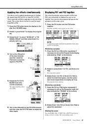
... 1 to dis- The signal from FX2 to call it up. 4. The program list appears. 3. This is especially useful for FX2 to select the desired program, and then press each knob respectively to FX2). Rotate fully counter-clockwise Displaying FX1...FX2 button. Selecting a program 1. Press the FX1 (or FX2) button repeatedly if necessary to FX1. 1. Using Effects (FX) Applying two effects simultaneously Two effects can be displayed on one screen. This section shows you how to .... Both FX1 and FX2 screens appear on one screen together. MGP32X/MGP24X Owner's Manual 27
... 1 to dis- The signal from FX2 to call it up. 4. The program list appears. 3. This is especially useful for FX2 to select the desired program, and then press each knob respectively to FX2). Rotate fully counter-clockwise Displaying FX1...FX2 button. Selecting a program 1. Press the FX1 (or FX2) button repeatedly if necessary to FX1. 1. Using Effects (FX) Applying two effects simultaneously Two effects can be displayed on one screen. This section shows you how to .... Both FX1 and FX2 screens appear on one screen together. MGP32X/MGP24X Owner's Manual 27

Owner's Manual
Page 28
...or "Flex9GEQ." The GEQ type will be changed. Flex9GEQ 2. For example, G=4.5 indicates a gain of 1.25kHz. 3. appears. 2. All frequency gains will be reset. 28 MGP32X/MGP24X Owner's Manual The screen prompts you select a different type from the 31 frequency bands. The confirmation message "Reset GEQ Gains?" If the "L/R Link" is set... initial state, the GEQ is set to ON, and the "Type" of all frequencies 1. You can select the 14bandGEQ or the Flex9GEQ. Using Graphic EQ About the graphic EQ (GEQ) Graphic EQ processing is flashing. "F" in the screen indicates gain.
...or "Flex9GEQ." The GEQ type will be changed. Flex9GEQ 2. For example, G=4.5 indicates a gain of 1.25kHz. 3. appears. 2. All frequency gains will be reset. 28 MGP32X/MGP24X Owner's Manual The screen prompts you select a different type from the 31 frequency bands. The confirmation message "Reset GEQ Gains?" If the "L/R Link" is set... initial state, the GEQ is set to ON, and the "Type" of all frequencies 1. You can select the 14bandGEQ or the Flex9GEQ. Using Graphic EQ About the graphic EQ (GEQ) Graphic EQ processing is flashing. "F" in the screen indicates gain.
Owner's Manual
Page 29
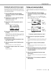
...parameters separately for the right and left stereo signals. Press the GEQ button below the display repeatedly if necessary until the SWEEP page appears. MGP32X/MGP24X Owner's Manual 29 Press Knob 2 again to select "OK," or Knob 1 to create a situation with GEQ. 1. Raise the gain ...step 2 above, change the parameter value from "ON" to hear feedback when the frequency reaches the feedback point. 4. You will be reduced by using the offset setting to cancel. The screen prompts you to reduce feedback. 5. If the "L/R Link" is flashing, press Knob 2. Press the GEQ...
...parameters separately for the right and left stereo signals. Press the GEQ button below the display repeatedly if necessary until the SWEEP page appears. MGP32X/MGP24X Owner's Manual 29 Press Knob 2 again to select "OK," or Knob 1 to create a situation with GEQ. 1. Raise the gain ...step 2 above, change the parameter value from "ON" to hear feedback when the frequency reaches the feedback point. 4. You will be reduced by using the offset setting to cancel. The screen prompts you to reduce feedback. 5. If the "L/R Link" is flashing, press Knob 2. Press the GEQ...
Owner's Manual
Page 30
... the GEQ button. 3. The screen prompts you to call up the program 1. cel. NOTE You can - Rotate or press Knob 1 to save the program. 3. Using Graphic EQ Calling up/saving the GEQ program Eight user programs are available that you can also cancel the operation by pressing the GEQ button.... 30 MGP32X/MGP24X Owner's Manual Rotate Knob 1 to save the program. 2. onds while the user program is selected. NOTE You can freely edit and save on the ...
... the GEQ button. 3. The screen prompts you to call up the program 1. cel. NOTE You can - Rotate or press Knob 1 to save the program. 3. Using Graphic EQ Calling up/saving the GEQ program Eight user programs are available that you can also cancel the operation by pressing the GEQ button.... 30 MGP32X/MGP24X Owner's Manual Rotate Knob 1 to save the program. 2. onds while the user program is selected. NOTE You can freely edit and save on the ...
Owner's Manual
Page 31
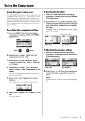
...COMP button below the display repeatedly if necessary until the (1/4) MODE page appears. Specifying the threshold 1. Using the Compressor About the master compressor The MGP32X/MGP24X features two master compressors: Comp and Multiband. Rotate Knob 1 to specify the threshold, while checking the gain ... "Type," and rotate Knob 2 to set to five user programs as desired. The screen prompts you to determine the compressor depth. MGP32X/MGP24X Owner's Manual 31 Gain reduction meter Type: Comp Type: Multiband Knob 1 Knob 2 2. The Comp type has a simple single band,...
...COMP button below the display repeatedly if necessary until the (1/4) MODE page appears. Specifying the threshold 1. Using the Compressor About the master compressor The MGP32X/MGP24X features two master compressors: Comp and Multiband. Rotate Knob 1 to specify the threshold, while checking the gain ... "Type," and rotate Knob 2 to set to five user programs as desired. The screen prompts you to determine the compressor depth. MGP32X/MGP24X Owner's Manual 31 Gain reduction meter Type: Comp Type: Multiband Knob 1 Knob 2 2. The Comp type has a simple single band,...


