
Owner's Manual
Page 2
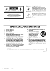
...openings. WARNING TO REDUCE THE RISK OF FIRE OR ELECTRIC SHOCK, DO NOT EXPOSE THIS APPARATUS TO RAIN OR MOISTURE. (UL60065_03) 2 MGP32X/MGP24X Owner's Manual IMPORTANT SAFETY INSTRUCTIONS 1 Read these instructions. 2 Keep these instructions. 3 Heed all warnings. 4 Follow all servicing to rain or... moisture, does not operate normally, or has been dropped. Servicing is used, use attachments/accessories specified by the manufacturer. 12 Use only with the cart, stand, tripod, bracket, or table specified by the manufacturer, or sold with one wider...
...openings. WARNING TO REDUCE THE RISK OF FIRE OR ELECTRIC SHOCK, DO NOT EXPOSE THIS APPARATUS TO RAIN OR MOISTURE. (UL60065_03) 2 MGP32X/MGP24X Owner's Manual IMPORTANT SAFETY INSTRUCTIONS 1 Read these instructions. 2 Keep these instructions. 3 Heed all warnings. 4 Follow all servicing to rain or... moisture, does not operate normally, or has been dropped. Servicing is used, use attachments/accessories specified by the manufacturer. 12 Use only with the cart, stand, tripod, bracket, or table specified by the manufacturer, or sold with one wider...
Owner's Manual
Page 3
... EQ (GEQ 28 Setting the GEQ 28 Finding and removing feedback 29 Calling up/saving the GEQ program 30 Using the Compressor 31 About the master compressor 31 Specifying the compressor settings 31 Calling up/saving the compressor program .....Using the Ducker function 37 Using the Leveler function 38 Initializing the unit to the factory default settings (resetting user memory)......... 39 Troubleshooting 40 Appendix 42 Message List 42 Effect Program List 43 Parameter List 44 Jack List 46 Dimensions 47 Specifications 48 Index 51 Block Diagram and Level Diagram 52 MGP32X/MGP24X...
... EQ (GEQ 28 Setting the GEQ 28 Finding and removing feedback 29 Calling up/saving the GEQ program 30 Using the Compressor 31 About the master compressor 31 Specifying the compressor settings 31 Calling up/saving the compressor program .....Using the Ducker function 37 Using the Leveler function 38 Initializing the unit to the factory default settings (resetting user memory)......... 39 Troubleshooting 40 Appendix 42 Message List 42 Effect Program List 43 Parameter List 44 Jack List 46 Dimensions 47 Specifications 48 Index 51 Block Diagram and Level Diagram 52 MGP32X/MGP24X...
Owner's Manual
Page 4
... make sure to prevent the internal temperature from the AC outlet when cleaning the device. 4 MGP32X/MGP24X Owner's Manual PA_en_1 1/2 Connections • Before connecting the device to use the voltage specified as candles, on it near heat sources such as vases, bottles or glasses) ... the following : Power supply/Power cord • When removing the electric plug from the outlet, and have the device inspected by qualified Yamaha service personnel. • Never insert or remove an electric plug with a protective grounding connection. Then have accumulated on the unit. The...
... make sure to prevent the internal temperature from the AC outlet when cleaning the device. 4 MGP32X/MGP24X Owner's Manual PA_en_1 1/2 Connections • Before connecting the device to use the voltage specified as candles, on it near heat sources such as vases, bottles or glasses) ... the following : Power supply/Power cord • When removing the electric plug from the outlet, and have the device inspected by qualified Yamaha service personnel. • Never insert or remove an electric plug with a protective grounding connection. Then have accumulated on the unit. The...
Owner's Manual
Page 5
...time at a high or uncomfortable volume level, since this device. • When cleaning the device, use of a TV, radio, stereo equipment, mobile phone, or other countries. Yamaha cannot be held responsible for iPhone" mean that is lost or destroyed. Information About copyrights &#...on the buttons, switches or connectors. • Do not use . Using the device while condensation is turned on the power amplifier LAST, to rapid, drastic changes in this can cause permanent hearing loss. PA_en_1 2/2 MGP32X/MGP24X Owner's Manual 5 Then have occurred, leave the device ...
...time at a high or uncomfortable volume level, since this device. • When cleaning the device, use of a TV, radio, stereo equipment, mobile phone, or other countries. Yamaha cannot be held responsible for iPhone" mean that is lost or destroyed. Information About copyrights &#...on the buttons, switches or connectors. • Do not use . Using the device while condensation is turned on the power amplifier LAST, to rapid, drastic changes in this can cause permanent hearing loss. PA_en_1 2/2 MGP32X/MGP24X Owner's Manual 5 Then have occurred, leave the device ...
Owner's Manual
Page 6
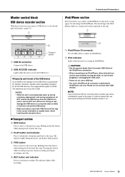
...16}" means channels 1-24 for the MGP32X and channels 1-16 for the MGP24X. * "CH" is built into the mixer: REVX (8 types) and SPX (16 types). The head amplifier features an inverted Darlington circuit* used in on the panel are distantly positioned, or when you a high-density..., richly reverberant sound ambience, with smooth attenuation, spread and depth that have different mastering levels. USB device recorder A USB device recorder is an abbreviation for purchasing the Yamaha MGP32X/MGP24X mixing ...
...16}" means channels 1-24 for the MGP32X and channels 1-16 for the MGP24X. * "CH" is built into the mixer: REVX (8 types) and SPX (16 types). The head amplifier features an inverted Darlington circuit* used in on the panel are distantly positioned, or when you a high-density..., richly reverberant sound ambience, with smooth attenuation, spread and depth that have different mastering levels. USB device recorder A USB device recorder is an abbreviation for purchasing the Yamaha MGP32X/MGP24X mixing ...
Owner's Manual
Page 7
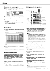
...panel) Faders 2. While producing sound on the channel PFL switch. Reverse this order every time you are off . NOTE • To use the mixer. MGP32X/MGP24X Owner's Manual 7 CAUTION • Unplug the power cord from the speakers, power up and down . Refer to the NOTE on page ... that the PFL/AFL level meter indicator only occasionally rises above the "0" level. • The gain (volume) level of each channel you use the level meter to adjust the volume. • Note that the corresponding peak indicators flash briefly at the highest peak levels. Connect the socket...
...panel) Faders 2. While producing sound on the channel PFL switch. Reverse this order every time you are off . NOTE • To use the mixer. MGP32X/MGP24X Owner's Manual 7 CAUTION • Unplug the power cord from the speakers, power up and down . Refer to the NOTE on page ... that the PFL/AFL level meter indicator only occasionally rises above the "0" level. • The gain (volume) level of each channel you use the level meter to adjust the volume. • Note that the corresponding peak indicators flash briefly at the highest peak levels. Connect the socket...
Owner's Manual
Page 9
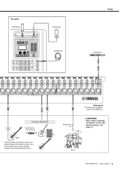
nected directly to ON (page 11). Microphone x 8 Rear panel *The illustrations show the panel of the MGP32X. Top panel USB device iPod/iPhone Headphones Setup Compressor Instrument, Microphone Bass * If electric guitars and basses can be con- Drum MGP32X/MGP24X Owner's Manual 9 CAUTION • When using a condenser microphone, set the +48V phantom switch to the mixer's inputs, use a DI box (direct box) or amp simulator between the instrument and the mixer.
nected directly to ON (page 11). Microphone x 8 Rear panel *The illustrations show the panel of the MGP32X. Top panel USB device iPod/iPhone Headphones Setup Compressor Instrument, Microphone Bass * If electric guitars and basses can be con- Drum MGP32X/MGP24X Owner's Manual 9 CAUTION • When using a condenser microphone, set the +48V phantom switch to the mixer's inputs, use a DI box (direct box) or amp simulator between the instrument and the mixer.
Owner's Manual
Page 11
... to the right the compression ratio increases while the output gain is on and off . all the way down when turning phantom power on when using one or more even dynamics because louder signals are for CH29/ 30, CH31/32 {CH21/ 22,CH23/24} only. As the knob is turned to... indicator comes on ( ), the mixer supplies DC +48V power to INPUT A of XLR input jacks • Do not connect/disconnect a cable to next page MGP32X/MGP24X Owner's Manual 11 STEREO master and GROUP faders- The adjustable sensitivity range is boosted. When this switch on /off . Turn this switch is fixed to...
... to the right the compression ratio increases while the output gain is on and off . all the way down when turning phantom power on when using one or more even dynamics because louder signals are for CH29/ 30, CH31/32 {CH21/ 22,CH23/24} only. As the knob is turned to... indicator comes on ( ), the mixer supplies DC +48V power to INPUT A of XLR input jacks • Do not connect/disconnect a cable to next page MGP32X/MGP24X Owner's Manual 11 STEREO master and GROUP faders- The adjustable sensitivity range is boosted. When this switch on /off . Turn this switch is fixed to...

Owner's Manual
Page 13
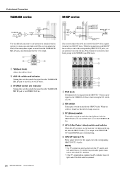
... and AUX6 buses. !5 AUX5, AUX6 switch Selects whether the channel's post-fader signal is cut off ( ), all of AUX 1-4 buses. NOTE • To enable use the PRE switch (!)3 to select whether the pre-fader or post-fader signal is being input to the channel. @0 Bus assign switches These switches determine... through the PHONES jack even when the ON switch is on ( ) sends that channel's signal to AUX buses 5 and 6 or FX buses l and 2. MGP32X/MGP24X Owner's Manual 13 If the switch is sent. NOTE To reduce noise, set the stereo pan position and determine the volume balance between left or...
... and AUX6 buses. !5 AUX5, AUX6 switch Selects whether the channel's post-fader signal is cut off ( ), all of AUX 1-4 buses. NOTE • To enable use the PRE switch (!)3 to select whether the pre-fader or post-fader signal is being input to the channel. @0 Bus assign switches These switches determine... through the PHONES jack even when the ON switch is on ( ) sends that channel's signal to AUX buses 5 and 6 or FX buses l and 2. MGP32X/MGP24X Owner's Manual 13 If the switch is sent. NOTE To reduce noise, set the stereo pan position and determine the volume balance between left or...
Owner's Manual
Page 15
... Please do NOT turn off and plugging or unplugging the USB cable. • Please do not use a USB hub. • The unit's iPod/iPhone IN connector is 2GB. Avoid inserting with ...move to alternately start /stop recording. Pressing this button while playing back forwards the song. MGP32X/MGP24X Owner's Manual 15 w iPod indicator Lights when the unit is FAT32. r PLAY button and .... The unit charges the iPod/ iPhone while it is connected to and recognized by Yamaha. (However, Yamaha cannot guarantee operation for the iPod/iPhone connection. • When connecting to an iPod...
... Please do NOT turn off and plugging or unplugging the USB cable. • Please do not use a USB hub. • The unit's iPod/iPhone IN connector is 2GB. Avoid inserting with ...move to alternately start /stop recording. Pressing this button while playing back forwards the song. MGP32X/MGP24X Owner's Manual 15 w iPod indicator Lights when the unit is FAT32. r PLAY button and .... The unit charges the iPod/ iPhone while it is connected to and recognized by Yamaha. (However, Yamaha cannot guarantee operation for the iPod/iPhone connection. • When connecting to an iPod...
Owner's Manual
Page 16
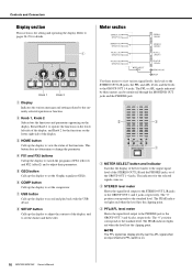
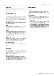
... to the PHONES jack or the GROUP OUT 3 and 4 jacks, respectively. w Knob 1, Knob 2 Selects/sets the functions and parameters appearing on . 16 MGP32X/MGP24X Owner's Manual Rotate Knob 1 to set the ducker and the leveler. y COMP button Calls up the display to operate the functions on the lower left... side of the GROUP OUT 1-4 jacks. u USB button Calls up the display to adjust their parameters. The indicators for the functions on . Use these meters can be monitored through the MONITOR OUT jacks and the PHONES jack. r FX1 and FX2 buttons Call up the display to adjust the...
... to the PHONES jack or the GROUP OUT 3 and 4 jacks, respectively. w Knob 1, Knob 2 Selects/sets the functions and parameters appearing on . 16 MGP32X/MGP24X Owner's Manual Rotate Knob 1 to set the ducker and the leveler. y COMP button Calls up the display to operate the functions on the lower left... side of the GROUP OUT 1-4 jacks. u USB button Calls up the display to adjust their parameters. The indicators for the functions on . Use these meters can be monitored through the MONITOR OUT jacks and the PHONES jack. r FX1 and FX2 buttons Call up the display to adjust the...
Owner's Manual
Page 20
... from the operator to musicians and studio staff. w AUX1-4 switch and indicator Turning this switch on . When the switch is pressed. 20 MGP32X/MGP24X Owner's Manual While the signal from each GROUP bus is positioned on the STEREO L/R buses when turning the ON switch (w) on sends the signal ... to the corresponding GROUP OUT 1-4 jacks. NOTE • The PFL signal has priority when both the PFL switch and AFL switch are also free to use the ST and AFL switches to selectively send these groups to the STEREO L/R bus. w ON switch Turning this switch on . r AFL (After-Fader...
... from the operator to musicians and studio staff. w AUX1-4 switch and indicator Turning this switch on . When the switch is pressed. 20 MGP32X/MGP24X Owner's Manual While the signal from each GROUP bus is positioned on the STEREO L/R buses when turning the ON switch (w) on sends the signal ... to the corresponding GROUP OUT 1-4 jacks. NOTE • The PFL signal has priority when both the PFL switch and AFL switch are also free to use the ST and AFL switches to selectively send these groups to the STEREO L/R bus. w ON switch Turning this switch on . r AFL (After-Fader...
Owner's Manual
Page 22
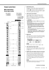
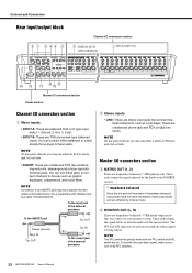
... output jacks that connect linelevel instruments, such as a CD player. NOTE On any given channel, you may use either an XLR or phone jack, but not both. Use a separately-sold Yamaha insertion cable (YIC025/050/070). These jacks output the signal adjusted by induced noise. r MONITOR OUT (L, ... • INSERT: These are TRS phone-jack type balanced inputs. These are on. You can use these jacks to connect channels to turn off all PFL switches. 22 MGP32X/MGP24X Owner's Manual Controls and Connectors Rear input/output block Channel I/O connectors section CH25/26-31/32 ...
... output jacks that connect linelevel instruments, such as a CD player. NOTE On any given channel, you may use either an XLR or phone jack, but not both. Use a separately-sold Yamaha insertion cable (YIC025/050/070). These jacks output the signal adjusted by induced noise. r MONITOR OUT (L, ... • INSERT: These are TRS phone-jack type balanced inputs. These are on. You can use these jacks to connect channels to turn off all PFL switches. 22 MGP32X/MGP24X Owner's Manual Controls and Connectors Rear input/output block Channel I/O connectors section CH25/26-31/32 ...
Owner's Manual
Page 23
... the product at the minimum level. After turning the unit OFF, wait for about 10 seconds before turning it by the MONO master fader. MGP32X/MGP24X Owner's Manual 23 y STEREO INSERT (L, R) These are no longer than 20mm. Refer to the power amplifier that drive your main speakers. !1...long time, make sure to turn off , electricity is turned off the power. Use these jacks to a separately sold gooseneck lamp (the Yamaha LA1L is an XLR-4-31 connector that are unbalanced TRS (tip=send/out; Use M5 screws that supplies power to connect a graphic equalizer or other signal processor. ...
... the product at the minimum level. After turning the unit OFF, wait for about 10 seconds before turning it by the MONO master fader. MGP32X/MGP24X Owner's Manual 23 y STEREO INSERT (L, R) These are no longer than 20mm. Refer to the power amplifier that drive your main speakers. !1...long time, make sure to turn off , electricity is turned off the power. Use these jacks to a separately sold gooseneck lamp (the Yamaha LA1L is an XLR-4-31 connector that are unbalanced TRS (tip=send/out; Use M5 screws that supplies power to connect a graphic equalizer or other signal processor. ...
Owner's Manual
Page 26
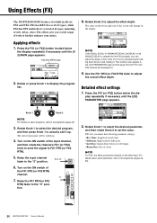
... on the display. Press the FX1 (or FX2) button located below the dis- This function also applies to FX1 RTN (or FX2 RTN). 5. Using Effects (FX) The MGP32X/MGP24X features two built-in finer units of 0.1ms by simultaneously holding down Knob 2 and rotating it up . 4. NOTE If 06 VOCAL ECHO, 07... ECHO, 08 DELAY, or 09 SINGLE DELAY is selected for the FX2 program, you a wide range of tools to the Appendix (pages 4445). 26 MGP32X/MGP24X Owner's Manual Rotate Knob 1 to select the desired program, and then press Knob 1 to adjust the overall effect depth. Raise the FX1 RTN (or FX2...
... on the display. Press the FX1 (or FX2) button located below the dis- This function also applies to FX1 RTN (or FX2 RTN). 5. Using Effects (FX) The MGP32X/MGP24X features two built-in finer units of 0.1ms by simultaneously holding down Knob 2 and rotating it up . 4. NOTE If 06 VOCAL ECHO, 07... ECHO, 08 DELAY, or 09 SINGLE DELAY is selected for the FX2 program, you a wide range of tools to the Appendix (pages 4445). 26 MGP32X/MGP24X Owner's Manual Rotate Knob 1 to select the desired program, and then press Knob 1 to adjust the overall effect depth. Raise the FX1 RTN (or FX2...
Owner's Manual
Page 27
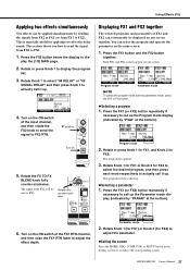
... then press Knob 1 to FX1. 1. Both FX1 and FX2 screens appear on one screen. Press the FX1 (or FX2) button repeatedly if necessary to FX2). Using Effects (FX) Applying two effects simultaneously Two effects can be applied simultaneously by sending the signals from FX2 to FX1 (or from FX1 to call... up the Program mode display (indicated by "PARAM" at the bottom). This is especially useful for FX2. Press the FX2 button below the display to the delay sound. Press the FX1 (or FX2) button repeatedly if necessary to call up...
... then press Knob 1 to FX1. 1. Both FX1 and FX2 screens appear on one screen. Press the FX1 (or FX2) button repeatedly if necessary to FX2). Using Effects (FX) Applying two effects simultaneously Two effects can be applied simultaneously by sending the signals from FX2 to FX1 (or from FX1 to call... up the Program mode display (indicated by "PARAM" at the bottom). This is especially useful for FX2. Press the FX2 button below the display to the delay sound. Press the FX1 (or FX2) button repeatedly if necessary to call up...

Owner's Manual
Page 28
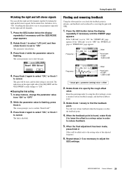
Using Graphic EQ About the graphic EQ (GEQ) Graphic EQ processing is flashing. Press the GEQ button below the display repeatedly if necessary until the EDIT ... inserted into the STEREO bus (L/R). Rotate Knob 1 to move the cursor to determine the frequency gain. appears. 2. All frequency gains will be reset. 28 MGP32X/MGP24X Owner's Manual Rotate Knob 1 to select "GEQ ON," and then rotate Knob 2 to set to "ON." 3. "F" in the screen indicates gain. "G" in the screen indicates...
Using Graphic EQ About the graphic EQ (GEQ) Graphic EQ processing is flashing. Press the GEQ button below the display repeatedly if necessary until the EDIT ... inserted into the STEREO bus (L/R). Rotate Knob 1 to move the cursor to determine the frequency gain. appears. 2. All frequency gains will be reset. 28 MGP32X/MGP24X Owner's Manual Rotate Knob 1 to select "GEQ ON," and then rotate Knob 2 to set to "ON." 3. "F" in the screen indicates gain. "G" in the screen indicates...
Owner's Manual
Page 29
... Rotate Knob 1 to select "L/R Link", and then rotate Knob 2 to set to specify the rough offset value. Finding and removing feedback Using the offset gain lets you to a minus value in advance, and feedback can edit the right and left channels together by...to cancel. Frequency Flex9GEQ Offset * Actual gain +4.5dB= -1.5dB+6.0dB * Actual gain = parameter (setting) value + offset 2. When the feedback point is executed. MGP32X/MGP24X Owner's Manual 29 While the parameter value is flashing. Press Knob 2 again to select "OK," or Knob 1 to adjust the GEQ settings. You will be...
... Rotate Knob 1 to select "L/R Link", and then rotate Knob 2 to set to specify the rough offset value. Finding and removing feedback Using the offset gain lets you to a minus value in advance, and feedback can edit the right and left channels together by...to cancel. Frequency Flex9GEQ Offset * Actual gain +4.5dB= -1.5dB+6.0dB * Actual gain = parameter (setting) value + offset 2. When the feedback point is executed. MGP32X/MGP24X Owner's Manual 29 While the parameter value is flashing. Press Knob 2 again to select "OK," or Knob 1 to adjust the GEQ settings. You will be...
Owner's Manual
Page 30
.... 3. The screen prompts you to call up the program list. 2. NOTE You can also cancel the operation by pressing the GEQ button. 30 MGP32X/MGP24X Owner's Manual The screen prompts you to call it up the program 1. The program will be overwritten. NOTE You can also cancel the operation by... for at least two seconds. Press Knob 2 to select "OK," or Knob 1 to actually call up the program list. Overwriting another user program 1. cel. Using Graphic EQ Calling up/saving the GEQ program Eight user programs are available that you can freely edit and save on the MGP32X...
.... 3. The screen prompts you to call up the program list. 2. NOTE You can also cancel the operation by pressing the GEQ button. 30 MGP32X/MGP24X Owner's Manual The screen prompts you to call it up the program 1. The program will be overwritten. NOTE You can also cancel the operation by... for at least two seconds. Press Knob 2 to select "OK," or Knob 1 to actually call up the program list. Overwriting another user program 1. cel. Using Graphic EQ Calling up/saving the GEQ program Eight user programs are available that you can freely edit and save on the MGP32X...
Owner's Manual
Page 31
... 1. Press the COMP button below the display repeatedly if necessary until the (1/4) MODE page appears. Specifying the threshold 1. MGP32X/MGP24X Owner's Manual 31 Using the Compressor About the master compressor The MGP32X/MGP24X features two master compressors: Comp and Multiband. There are linked. Rotate Knob 1 to select "COMP ON," and rotate Knob...
... 1. Press the COMP button below the display repeatedly if necessary until the (1/4) MODE page appears. Specifying the threshold 1. MGP32X/MGP24X Owner's Manual 31 Using the Compressor About the master compressor The MGP32X/MGP24X features two master compressors: Comp and Multiband. There are linked. Rotate Knob 1 to select "COMP ON," and rotate Knob...


