
Owner's Manual
Page 4
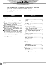
... ten input channels and mixes the signals into different channels. Introduction Thank you will be able to take full advantage of the YAMAHA MG10/2 mixing console. Input channels 7/8 and 9/10 are each equipped with both a TRS line input jack and an RCA line input jack. ... Making Better Mixes 15 Front & Rear Panels 17 Channel Control Section 17 Master Control Section 18 Input/Output Section 19 Rear Section 20 Setting Up 21 Setup Procedure 21 Setup Examples 21 Mounting to stereo-output synthesizers. This mixing console combines ease of connectors enables connection to many...
... ten input channels and mixes the signals into different channels. Introduction Thank you will be able to take full advantage of the YAMAHA MG10/2 mixing console. Input channels 7/8 and 9/10 are each equipped with both a TRS line input jack and an RCA line input jack. ... Making Better Mixes 15 Front & Rear Panels 17 Channel Control Section 17 Master Control Section 18 Input/Output Section 19 Rear Section 20 Setting Up 21 Setup Procedure 21 Setup Examples 21 Mounting to stereo-output synthesizers. This mixing console combines ease of connectors enables connection to many...
Owner's Manual
Page 7
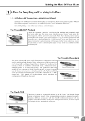
...-Ring-Sleeve, which describes the configuration of the phone plug used much these different types of signal they're designed to encounter when setting up a system for the first time might include "Why all these days-besides, it handles, as will also handle unbalanced signals with... connector is also often referred to as do keep your mixer to use this type of signal it 's too easily confusable with no problem. Female MG10/2 7 Phone jacks can 't always tell what type of connector, as a "TRS" phone jack. RCA pin jacks are always unbalanced, and generally carry a...
...-Ring-Sleeve, which describes the configuration of the phone plug used much these different types of signal they're designed to encounter when setting up a system for the first time might include "Why all these days-besides, it handles, as will also handle unbalanced signals with... connector is also often referred to as do keep your mixer to use this type of signal it 's too easily confusable with no problem. Female MG10/2 7 Phone jacks can 't always tell what type of connector, as a "TRS" phone jack. RCA pin jacks are always unbalanced, and generally carry a...
Owner's Manual
Page 9
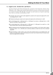
...will accept a very wide range of measure used to match the input's sensitivity to the signal. MG10/2 9 Here are a very versatile unit of input levels because the control can get confusing because...Inputs that let you are a number of -10 dB. Making the Most Of Your Mixer 1-3. More on your Yamaha mixer-will result in mind: G "Consumer" gear (such as electronic signal levels. Fortunately, you don't need... a "Gain" control-such as the mono-channel inputs on this later. Be sure to set these switches to overload the input. G You should always feed -10 dB inputs with a...
...will accept a very wide range of measure used to match the input's sensitivity to the signal. MG10/2 9 Here are a very versatile unit of input levels because the control can get confusing because...Inputs that let you are a number of -10 dB. Making the Most Of Your Mixer 1-3. More on your Yamaha mixer-will result in mind: G "Consumer" gear (such as electronic signal levels. Fortunately, you don't need... a "Gain" control-such as the mono-channel inputs on this later. Be sure to set these switches to overload the input. G You should always feed -10 dB inputs with a...

Owner's Manual
Page 10
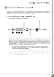
... usually the only stage with the way these things work. 2-1. Here's a greatly simplified block diagram of a generic mixer to cut than boost. 10 MG10/2 3 Channel Peak LED & Fader The channel peak LED is located after the head amp and EQ stage. There could be simple bass and treble controls...;ows in any mixer. In reality, block diagrams are assigned to match the level of buses or outputs it is your most valuable tool for setting the input "gain" control for optimum performance.
... usually the only stage with the way these things work. 2-1. Here's a greatly simplified block diagram of a generic mixer to cut than boost. 10 MG10/2 3 Channel Peak LED & Fader The channel peak LED is located after the head amp and EQ stage. There could be simple bass and treble controls...;ows in any mixer. In reality, block diagrams are assigned to match the level of buses or outputs it is your most valuable tool for setting the input "gain" control for optimum performance.
Owner's Manual
Page 11
... every "stage" in the mixer's signal path will add a certain amount of the audio signal passing through the circuit. This means that levels are properly set for achieving optimum performance from your mixer! The thing to it. The Head Amplifier "Gain" Control Is the Key! Making the Most Of... level at later stages, which will only amplify the noise contributed by each individual source. If you will overload our channel circuitry and cause clipping. MG10/2 11
... every "stage" in the mixer's signal path will add a certain amount of the audio signal passing through the circuit. This means that levels are properly set for achieving optimum performance from your mixer! The thing to it. The Head Amplifier "Gain" Control Is the Key! Making the Most Of... level at later stages, which will only amplify the noise contributed by each individual source. If you will overload our channel circuitry and cause clipping. MG10/2 11
Owner's Manual
Page 12
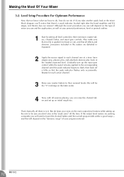
... or bypassed. 2 Apply the source signal to it ? Repeat for each active channel. 3 Raise your personal preferences, here's a general outline: 1 Start by setting all level controls to their nominal levels (this will need to flash, then back off a little so that there's a peak indicator located right after...sure you use and the application, as well as your master fader(s) to do, how do we do keep your program material. 12 MG10/2 Making the Most Of Your Mixer 3-2. Level Setup Procedure For Optimum Performance Now that all sources playing, you can raise the channel faders ...
... or bypassed. 2 Apply the source signal to it ? Repeat for each active channel. 3 Raise your personal preferences, here's a general outline: 1 Start by setting all level controls to their nominal levels (this will need to flash, then back off a little so that there's a peak indicator located right after...sure you use and the application, as well as your master fader(s) to do, how do we do keep your program material. 12 MG10/2 Making the Most Of Your Mixer 3-2. Level Setup Procedure For Optimum Performance Now that all sources playing, you can raise the channel faders ...
Owner's Manual
Page 15
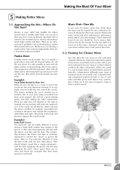
... you 'll probably end up developing a system that have a similar sound. There are in which channel should you start with all faders at their nominal settings, but it's too easy to it that way, but a more systematic approach that it guide the mix, rather than working with ? Example1: Vocal Ballad Backed... is easy, right? You're using a hightech tool to how the bass works with the drums, and then add the bass. Approach it sounds right? MG10/2 15
... you 'll probably end up developing a system that have a similar sound. There are in which channel should you start with all faders at their nominal settings, but it's too easy to it that way, but a more systematic approach that it guide the mix, rather than working with ? Example1: Vocal Ballad Backed... is easy, right? You're using a hightech tool to how the bass works with the drums, and then add the bass. Approach it sounds right? MG10/2 15
Owner's Manual
Page 16
...is playing solo. There are many situations in the midrange can give the overall sound better definition. Naturally you like. The way you set up the mix rather than trying to boost the mix into this trap start with the mix. To avoid falling into clarity. You don't ... circuitry. 5-4. But if you choose will have room to dominate the mix unless you can interfere with caution. One of a bass guitar, for . 16 MG10/2 A little extra time spent matching the reverb time to the music being mixed can often roll off to kick drums and bass guitars: you 'll...
...is playing solo. There are many situations in the midrange can give the overall sound better definition. Naturally you like. The way you set up the mix rather than trying to boost the mix into this trap start with the mix. To avoid falling into clarity. You don't ... circuitry. 5-4. But if you choose will have room to dominate the mix unless you can interfere with caution. One of a bass guitar, for . 16 MG10/2 A little extra time spent matching the reverb time to the music being mixed can often roll off to kick drums and bass guitars: you 'll...
Owner's Manual
Page 17
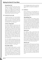
... AUX buses. NOTE To reduce noise, set the knob exactly to the M position, the mixer will always pass through the MIC jack or into both PAN and BAL controls: The knob operates as a PAN control if you are mixed and sent to the channel. MG10/2 17 To get the best balance between... Shelving 10 kHz Peaking 2.5 kHz ±15 dB Shelving 100 Hz 5 AUX Controls Use the AUX control to send the channel's signal to the minimum setting). The signal to the AUX2 bus is not affected by the channel fader. Use these levels reaches 3 dB below the clipping level. 3 Switch (High Pass...
... AUX buses. NOTE To reduce noise, set the knob exactly to the M position, the mixer will always pass through the MIC jack or into both PAN and BAL controls: The knob operates as a PAN control if you are mixed and sent to the channel. MG10/2 17 To get the best balance between... Shelving 10 kHz Peaking 2.5 kHz ±15 dB Shelving 100 Hz 5 AUX Controls Use the AUX control to send the channel's signal to the minimum setting). The signal to the AUX2 bus is not affected by the channel fader. Use these levels reaches 3 dB below the clipping level. 3 Switch (High Pass...
Owner's Manual
Page 18
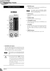
... damage may be left on ( ) without problem when connecting to balanced dynamic microphones. • To avoid damage to speakers, be sure to turn off . 18 MG10/2 If you supply a signal to the RETURN L (MONO) jack only, the mixer outputs the identical signal to both the L and R Stereo buses. 3 2TR IN Control... note that the switch may result if you connect to an unbalanced device or to an ungrounded transformer while this switch off . NOTE If you set the switch on or off amplifiers (or powered speakers) before turning this switch on , the mixer supplies power to all XLR-type MIC...
... damage may be left on ( ) without problem when connecting to balanced dynamic microphones. • To avoid damage to speakers, be sure to turn off . 18 MG10/2 If you supply a signal to the RETURN L (MONO) jack only, the mixer outputs the identical signal to both the L and R Stereo buses. 3 2TR IN Control... note that the switch may result if you connect to an unbalanced device or to an ungrounded transformer while this switch off . NOTE If you set the switch on or off amplifiers (or powered speakers) before turning this switch on , the mixer supplies power to all XLR-type MIC...
Owner's Manual
Page 20
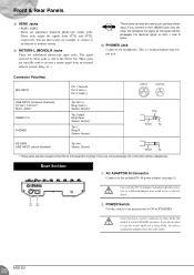
...ADAPTOR IN Connector Connects to the included PA-10 power adaptor (see page 5). 12 Use only the PA-10 adaptor included with this switch to set mixer power to ON or STANDBY. Note that trace current continues to flow while the switch is a balanced phone-type output jack. ... Jacks • AUX1, AUX2 These are typically used as monaural and will also accept connection to unplug the adaptor from the wall outlet. 20 MG10/2 If you use the mixer again for headphones. These jacks are impedance balanced phone-type output jacks. The signal received by these jacks, for ...
...ADAPTOR IN Connector Connects to the included PA-10 power adaptor (see page 5). 12 Use only the PA-10 adaptor included with this switch to set mixer power to ON or STANDBY. Note that trace current continues to flow while the switch is a balanced phone-type output jack. ... Jacks • AUX1, AUX2 These are typically used as monaural and will also accept connection to unplug the adaptor from the wall outlet. 20 MG10/2 If you use the mixer again for headphones. These jacks are impedance balanced phone-type output jacks. The signal received by these jacks, for ...
Owner's Manual
Page 21
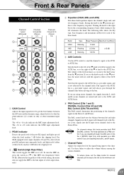
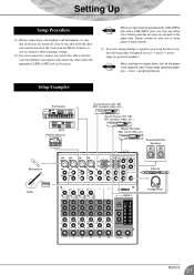
Setting Up Setup Procedure (1) Before connecting to microphones and instruments, be sure that all of the controls in the Master Control ...or instrument and connect the other end to the appropriate LINE or MIC jack on each channel. (3) To avoid causing damage to their minimum settings. (2) For each connection, connect one of these jacks on the mixer. NOTE When shutting the system down, turn off . NOTE Where ... video, etc.) Sound Source (CD, MD, DAT, cassette, video, etc.) Master Recorder (MD, CD-R, DAT, etc.) Powered Monitor Speakers Effector Guitar Headphones MG10/2 21
Setting Up Setup Procedure (1) Before connecting to microphones and instruments, be sure that all of the controls in the Master Control ...or instrument and connect the other end to the appropriate LINE or MIC jack on each channel. (3) To avoid causing damage to their minimum settings. (2) For each connection, connect one of these jacks on the mixer. NOTE When shutting the system down, turn off . NOTE Where ... video, etc.) Sound Source (CD, MD, DAT, cassette, video, etc.) Master Recorder (MD, CD-R, DAT, etc.) Powered Monitor Speakers Effector Guitar Headphones MG10/2 21
Owner's Manual
Page 22
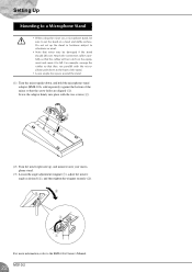
...Turn the mixer right-side up the stand in locations subject to vibrations or wind. • Note that the screw holes are aligned (1). Do not set the stand on the equipment and cause it onto your microphone stand. (3) Loosen the angle adjustment wingnut (1), adjust the mixer's angle as desired (2),... and then tighten the wingnut securely (3). 2 3 1 For more information, refer to the BMS-10A Owner's Manual. 22 MG10/2 sold separately) against the bottom of the stand. • Leave ample free space around the stand. (1) Turn the mixer upside-down, and hold the...
...Turn the mixer right-side up the stand in locations subject to vibrations or wind. • Note that the screw holes are aligned (1). Do not set the stand on the equipment and cause it onto your microphone stand. (3) Loosen the angle adjustment wingnut (1), adjust the mixer's angle as desired (2),... and then tighten the wingnut securely (3). 2 3 1 For more information, refer to the BMS-10A Owner's Manual. 22 MG10/2 sold separately) against the bottom of the stand. • Leave ample free space around the stand. (1) Turn the mixer upside-down, and hold the...
Owner's Manual
Page 24
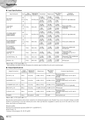
...Where 0 dBu = 0.775 V and 0 dBV= 1 V * Input sensitivity: the lowest level that will produce the nominal output level when the unit is set to change or modify products or specifications at any time without prior notice. S: ground]) PHONES 100 Ω 40 Ω phone 3 mW 75 mW...cold; reserves the right to maximum gain. R: in EN55103-1 and EN55103-2. Inrush Current: 3A Conforms to Environments: E1, E2, E3 and E4 24 MG10/2 R: cold; R: cold; Yamaha Corp. Since specifications, equipment or options may not be the same in every locale, please check with your...
...Where 0 dBu = 0.775 V and 0 dBV= 1 V * Input sensitivity: the lowest level that will produce the nominal output level when the unit is set to change or modify products or specifications at any time without prior notice. S: ground]) PHONES 100 Ω 40 Ω phone 3 mW 75 mW...cold; reserves the right to maximum gain. R: in EN55103-1 and EN55103-2. Inrush Current: 3A Conforms to Environments: E1, E2, E3 and E4 24 MG10/2 R: cold; R: cold; Yamaha Corp. Since specifications, equipment or options may not be the same in every locale, please check with your...


