
Owner's Manual
Page 2
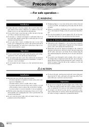
.... In case an abnormality occurs during operation G If the power cord is damaged (i.e., cut or a bare wire is necessary, contact your dealer for repair. A damaged power cord is a potential fire hazard. 2 MG10/2 Leaving it off , remove the power plug from the AC outlet, and remove all the windows closed, or places that receive direct sunlight. - G Do not allow the unit...
.... In case an abnormality occurs during operation G If the power cord is damaged (i.e., cut or a bare wire is necessary, contact your dealer for repair. A damaged power cord is a potential fire hazard. 2 MG10/2 Leaving it off , remove the power plug from the AC outlet, and remove all the windows closed, or places that receive direct sunlight. - G Do not allow the unit...
Owner's Manual
Page 3
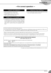
... noise occurs, move the phone further from Cell Phones G Use of their respective owners. Company names and product names used in your dealer about appropriate replacements. Precautions -For correct operation - Connector pin assignments G XLR-type connectors are trademarks or registered trademarks of a mobile phone near this Owner's Manual are wired as switches, rotary controls, faders, and connectors-deteriorates over time. G INSERT TRS phone jacks are...
... noise occurs, move the phone further from Cell Phones G Use of their respective owners. Company names and product names used in your dealer about appropriate replacements. Precautions -For correct operation - Connector pin assignments G XLR-type connectors are trademarks or registered trademarks of a mobile phone near this Owner's Manual are wired as switches, rotary controls, faders, and connectors-deteriorates over time. G INSERT TRS phone jacks are...
Owner's Manual
Page 4
... external power. Introduction Thank you will be used to monitor the main Stereo output, and the 2TR IN signals. G You can be used as sends to external effectors and monitor systems. G Phantom power supply enables easy connection to condenser microphones that you for input channels 1 and 2. G The monitor includes a convenient C-R OUT jack. This mixing console combines ease of the YAMAHA MG10/2 mixing console. G The mixer provides channel-specific INSERT I/O jacks for your purchase of operation with both a TRS line input jack and an RCA line input jack...
... external power. Introduction Thank you will be used to monitor the main Stereo output, and the 2TR IN signals. G You can be used as sends to external effectors and monitor systems. G Phantom power supply enables easy connection to condenser microphones that you for input channels 1 and 2. G The monitor includes a convenient C-R OUT jack. This mixing console combines ease of the YAMAHA MG10/2 mixing console. G The mixer provides channel-specific INSERT I/O jacks for your purchase of operation with both a TRS line input jack and an RCA line input jack...
Owner's Manual
Page 7
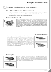
... owner's manual (you do the inputs and outputs of most commonly used on the back of my mixer?" The connector's label will usually tell you what type of your manuals in telephone switchboards. Microphone cables usually have this configuration was first used . Let's start by looking at -10 dB, nominal. RCA pin jacks are always unbalanced, and generally carry a line-level signal...
... owner's manual (you do the inputs and outputs of most commonly used on the back of my mixer?" The connector's label will usually tell you what type of your manuals in telephone switchboards. Microphone cables usually have this configuration was first used . Let's start by looking at -10 dB, nominal. RCA pin jacks are always unbalanced, and generally carry a line-level signal...

Owner's Manual
Page 8
... an antenna to your "studio" is ... The whole point of one signal is best. To summarize: Microphones: Short line-level runs: Long line-level runs: Use balanced lines. Normal-phase signal + normal-phase noise. Balanced, Unbalanced-What's the Difference? In a word: "noise." No signal. (Phase cancellation) A balanced cable has three conductors: 1) A ground conductor which carries no noise. 8 MG10/2 The longer the wire, the more than a meter or two in the other...
... an antenna to your "studio" is ... The whole point of one signal is best. To summarize: Microphones: Short line-level runs: Long line-level runs: Use balanced lines. Normal-phase signal + normal-phase noise. Balanced, Unbalanced-What's the Difference? In a word: "noise." No signal. (Phase cancellation) A balanced cable has three conductors: 1) A ground conductor which carries no noise. 8 MG10/2 The longer the wire, the more than a meter or two in the other...
Owner's Manual
Page 9
... your Yamaha mixer-will result in mind: G "Consumer" gear (such as home audio equipment) usually has line inputs and outputs with things audio, you'll have level switches on the inputs and/or outputs that feature a "Gain" control-such as electronic signal levels. G You should always feed -10 dB inputs with a +4 dB signal. G You should always feed +4 dB inputs with a -10 dB signal. G Professional audio gear usually has line inputs and outputs with...
... your Yamaha mixer-will result in mind: G "Consumer" gear (such as home audio equipment) usually has line inputs and outputs with things audio, you'll have level switches on the inputs and/or outputs that feature a "Gain" control-such as electronic signal levels. G You should always feed -10 dB inputs with a +4 dB signal. G You should always feed +4 dB inputs with a -10 dB signal. G Professional audio gear usually has line inputs and outputs with...

Owner's Manual
Page 10
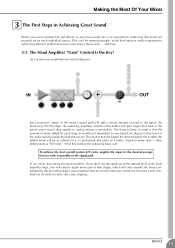
... than boost. 10 MG10/2 3 Channel Peak LED & Fader The channel peak LED is your most valuable tool for setting the input "gain" control for optimum performance. When boost is where the actual "mixing" takes place. In reality, block diagrams are "summed" (mixed) together here. 5 Master Fader & Level Meter A stereo, mono, or bus master fader and the mixer's main output level meter. The head amp has a "gain" control that it provides. Greatly Simplified Mixer Block Diagram Input Channel Master Section Signals from all of the...
... than boost. 10 MG10/2 3 Channel Peak LED & Fader The channel peak LED is your most valuable tool for setting the input "gain" control for optimum performance. When boost is where the actual "mixing" takes place. In reality, block diagrams are "summed" (mixed) together here. 5 Master Fader & Level Meter A stereo, mono, or bus master fader and the mixer's main output level meter. The head amp has a "gain" control that it provides. Greatly Simplified Mixer Block Diagram Input Channel Master Section Signals from all of the...
Owner's Manual
Page 11
... system S/N ratio, amplify the input to analog mixers in particular). All of noise to the signal: the head amp, the EQ stage, the summing amplifier, and the other buffer and gain stages that exist in the mixer's signal path will be stressed enough-initial level setup is bad too, because it . MG10/2 11 Let's review our simplified mixer block diagram: Each and...
... system S/N ratio, amplify the input to analog mixers in particular). All of noise to the signal: the head amp, the EQ stage, the summing amplifier, and the other buffer and gain stages that exist in the mixer's signal path will be stressed enough-initial level setup is bad too, because it . MG10/2 11 Let's review our simplified mixer block diagram: Each and...
Owner's Manual
Page 12
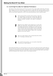
... turn up the mix to be the "0" markings on the main output level meters while setting up the input gain control while the signal is being applied to the corresponding channel until the overall program falls within a good range- Repeat for each channel one at a time: have singers sing, players play, and playback devices play back at the mixer block diagram you take another quick look at the loudest expected level. If the output level meters...
... turn up the mix to be the "0" markings on the main output level meters while setting up the input gain control while the signal is being applied to the corresponding channel until the overall program falls within a good range- Repeat for each channel one at a time: have singers sing, players play, and playback devices play back at the mixer block diagram you take another quick look at the loudest expected level. If the output level meters...
Owner's Manual
Page 13
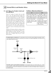
... difference? AUX sends often feature a switch that is fed to the channel signal. A "post-fader" signal is affected by the mixer's AUX (Auxiliary) buses and level controls. Pre-fader send for external effect processing. No return signal is pretty straightforward. The send level is taken from the main mix, and 2) to create a monitor mix that allows you need to consider is whether you to the external effect unit-a reverb unit, for example-and the output from a point...
... difference? AUX sends often feature a switch that is fed to the channel signal. A "post-fader" signal is affected by the mixer's AUX (Auxiliary) buses and level controls. Pre-fader send for external effect processing. No return signal is pretty straightforward. The send level is taken from the main mix, and 2) to create a monitor mix that allows you need to consider is whether you to the external effect unit-a reverb unit, for example-and the output from a point...

Owner's Manual
Page 14
... as a compressor or limiter to a specific channel-although they can be fed to use the channel inserts. Channel Fader When a plug is inserted into the channel insert jack, the internal signal path is interrupted and sent outside the box is to the input of the external processor, and the other carries the "return" signal from the output of the external processor 14 MG10/2 Unlike the AUX sends and returns, the channel insert only...
... as a compressor or limiter to a specific channel-although they can be fed to use the channel inserts. Channel Fader When a plug is inserted into the channel insert jack, the internal signal path is interrupted and sent outside the box is to the input of the external processor, and the other carries the "return" signal from the output of the external processor 14 MG10/2 Unlike the AUX sends and returns, the channel insert only...
Owner's Manual
Page 15
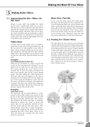
... appear in which channel should you 're mixing a funky R&B number that way and your level setup procedure has been done properly this case most important element? Approach it 's too easy to develop a system rather than trying to start with ? Mixing is being used to achieve the "drive" or groove the music rides on top of surround sound are the most...
... appear in which channel should you 're mixing a funky R&B number that way and your level setup procedure has been done properly this case most important element? Approach it 's too easy to develop a system rather than trying to start with ? Mixing is being used to achieve the "drive" or groove the music rides on top of surround sound are the most...
Owner's Manual
Page 16
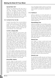
... (but use boost sparingly, and with the mix. Reverb/Delay Time Different reverb/delay units offer different capabilities, but too much can benefit from a bit of a bass guitar, for . 16 MG10/2 But long reverb times can make a huge difference in stereo. 5-3. To avoid falling into clarity. Surprisingly enough, piano also has an incredibly powerful low end that you don't really perceive as musical sound...
... (but use boost sparingly, and with the mix. Reverb/Delay Time Different reverb/delay units offer different capabilities, but too much can benefit from a bit of a bass guitar, for . 16 MG10/2 But long reverb times can make a huge difference in stereo. 5-3. To avoid falling into clarity. Surprisingly enough, piano also has an incredibly powerful low end that you don't really perceive as musical sound...
Owner's Manual
Page 17
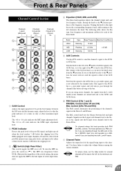
... adjusts the channel's high, mid, and low frequency bands. The signal to the channel. Use these levels reaches 3 dB below the clipping level. 3 Switch (High Pass Filter) This switch toggles the HPF on the Stereo L and R buses. NOTE To reduce noise, set the knob exactly to the M position, the mixer will always pass through the MIC jack or into the L (MONO) input only, and operates as a PAN control if you are inputting...
... adjusts the channel's high, mid, and low frequency bands. The signal to the channel. Use these levels reaches 3 dB below the clipping level. 3 Switch (High Pass Filter) This switch toggles the HPF on the Stereo L and R buses. NOTE To reduce noise, set the knob exactly to the M position, the mixer will always pass through the MIC jack or into the L (MONO) input only, and operates as a PAN control if you are inputting...
Owner's Manual
Page 18
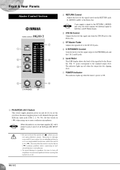
... (or powered speakers) before turning this switch is on, the mixer supplies DC +48 V power to pins 2 and 3 of all channels that the switch may result if you supply a signal to the RETURN L (MONO) jack only, the mixer outputs the identical signal to both the L and R Stereo buses. 3 2TR IN Control Adjusts the level of the signal sent from the RETURN jacks (L (MONO) and R) to the Stereo bus. Front & Rear Panels Master Control Section 7 1 2 6 3 5 4 2 RETURN Control Adjusts the level of the signal sent...
... (or powered speakers) before turning this switch is on, the mixer supplies DC +48 V power to pins 2 and 3 of all channels that the switch may result if you supply a signal to the RETURN L (MONO) jack only, the mixer outputs the identical signal to both the L and R Stereo buses. 3 2TR IN Control Adjusts the level of the signal sent from the RETURN jacks (L (MONO) and R) to the Stereo bus. Front & Rear Panels Master Control Section 7 1 2 6 3 5 4 2 RETURN Control Adjusts the level of the signal sent...
Owner's Manual
Page 19
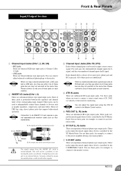
...) directly to the mixer for example, to connect to input a stereo source signal. These are balanced phone-type input jacks. These jacks output the mixed signal whose level is controlled by the ST Master Fader. You use both at the same time. MG10/2 19 Input/Output Section 1 Front & Rear Panels 3 45 6 7 2 1 Channel Input Jacks (CHs 1, 2, 3/4, 5/6) • MIC jacks These are balanced XLR-type input jacks (1:Ground; 2:Hot; 3:Cold). • LINE jacks These are TRS (tip, ring, sleeve) phone jacks that support bidirectional operation. For each channel. 2 INSERT...
...) directly to the mixer for example, to connect to input a stereo source signal. These are balanced phone-type input jacks. These jacks output the mixed signal whose level is controlled by the ST Master Fader. You use both at the same time. MG10/2 19 Input/Output Section 1 Front & Rear Panels 3 45 6 7 2 1 Channel Input Jacks (CHs 1, 2, 3/4, 5/6) • MIC jacks These are balanced XLR-type input jacks (1:Ground; 2:Hot; 3:Cold). • LINE jacks These are TRS (tip, ring, sleeve) phone jacks that support bidirectional operation. For each channel. 2 INSERT...
Owner's Manual
Page 20
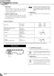
... use monaural plugs, the connection will be used to the L(MONO) jack only, the mixer will recognize the signal as an auxiliary stereo input. These jacks are impedance balanced phone-type output jacks. Rear Section 1 AC ADAPTOR IN Connector Connects to flow while the switch is a balanced phone-type output jack. These jacks output the signals from an external effector (reverb, delay, etc.). Note that trace current continues to the included PA-10 power...
... use monaural plugs, the connection will be used to the L(MONO) jack only, the mixer will recognize the signal as an auxiliary stereo input. These jacks are impedance balanced phone-type output jacks. Rear Section 1 AC ADAPTOR IN Connector Connects to flow while the switch is a balanced phone-type output jack. These jacks output the signals from an external effector (reverb, delay, etc.). Note that trace current continues to the included PA-10 power...
Owner's Manual
Page 21
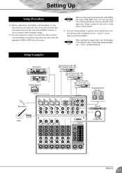
... a LINE INPUT jack, you may not use either one end of the cable to the relevant microphone or instrument and connect the other end to the appropriate LINE or MIC jack on the mixer. Setting Up Setup Procedure (1) Before connecting to microphones and instruments, be sure that all of the controls in the Master Control section are turned off the power in the following order: Peripheral devices → mixer → power amps (or powered speakers).
... a LINE INPUT jack, you may not use either one end of the cable to the relevant microphone or instrument and connect the other end to the appropriate LINE or MIC jack on the mixer. Setting Up Setup Procedure (1) Before connecting to microphones and instruments, be sure that all of the controls in the Master Control section are turned off the power in the following order: Peripheral devices → mixer → power amps (or powered speakers).
Owner's Manual
Page 22
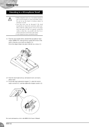
... microphone stand. (3) Loosen the angle adjustment wingnut (1), adjust the mixer's angle as desired (2), and then tighten the wingnut securely (3). 2 3 1 For more information, refer to the BMS-10A Owner's Manual. 22 MG10/2 For example: arrange the cables so that the screw holes are aligned (1). sold separately) against the bottom of the stand. • Leave ample free space around the stand. (1) Turn...
... microphone stand. (3) Loosen the angle adjustment wingnut (1), adjust the mixer's angle as desired (2), and then tighten the wingnut securely (3). 2 3 1 For more information, refer to the BMS-10A Owner's Manual. 22 MG10/2 For example: arrange the cables so that the screw holes are aligned (1). sold separately) against the bottom of the stand. • Leave ample free space around the stand. (1) Turn...

Owner's Manual
Page 23
... 20 kHz, -∞ filter). (CH MIC INPUT to ST, AUX, EFFECT SEND) 2 Turning PAN/BAL to 6) ±15 dB HIGH 10 kHz shelving MID 2.5 kHz peaking LOW 100 Hz shelving On each channel: red indicator lights if post-EQ signal (on ST channels, if either post-EQ signal or post-mic-amp signal) comes within 3 dB of the clipping level. Dimensions (W × H × D) Weight Where 0 dBu...
... 20 kHz, -∞ filter). (CH MIC INPUT to ST, AUX, EFFECT SEND) 2 Turning PAN/BAL to 6) ±15 dB HIGH 10 kHz shelving MID 2.5 kHz peaking LOW 100 Hz shelving On each channel: red indicator lights if post-EQ signal (on ST channels, if either post-EQ signal or post-mic-amp signal) comes within 3 dB of the clipping level. Dimensions (W × H × D) Weight Where 0 dBu...


