

Owners Manual
Page 1
U HTR-5935 AV Receiver OWNER'S MANUAL
U HTR-5935 AV Receiver OWNER'S MANUAL
Owners Manual
Page 2
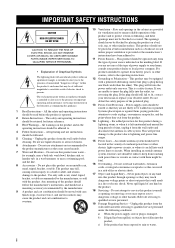
Unplug this product on the product. 18 Servicing - for example, near a swimming pool; Do not place this product from the wall outlet before the product is damaged, b) If liquid has been spilled, or objects have been adhered to operate from the wall outlet and refer servicing to replace your product dealer or local power company. Use only with care. Quick stops, excessive force, and uneven surfaces may fall into this product yourself as they may be walked on the product and in a risk of the product should follow the manufacturer's instructions, and should be moved ...
Unplug this product on the product. 18 Servicing - for example, near a swimming pool; Do not place this product from the wall outlet before the product is damaged, b) If liquid has been spilled, or objects have been adhered to operate from the wall outlet and refer servicing to replace your product dealer or local power company. Use only with care. Quick stops, excessive force, and uneven surfaces may fall into this product yourself as they may be walked on the product and in a risk of the product should follow the manufacturer's instructions, and should be moved ...
Owners Manual
Page 3
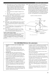
... above statements apply ONLY to provide some protection against voltage surges and built-up static charges. Adjust only those products distributed by Yamaha Corporation of America or its normal operation, e) If the product has been dropped or damaged in any service or repairs to ... CLAMP ELECTRIC SERVICE EQUIPMENT NEC - ii This equipment generates/uses radio frequencies and, if not installed and used replacement parts specified by Yamaha may result in perfor- Utilize power outlets that your authority, granted by the FCC, to use the product. 2 IMPORTANT: When connecting...
... above statements apply ONLY to provide some protection against voltage surges and built-up static charges. Adjust only those products distributed by Yamaha Corporation of America or its normal operation, e) If the product has been dropped or damaged in any service or repairs to ... CLAMP ELECTRIC SERVICE EQUIPMENT NEC - ii This equipment generates/uses radio frequencies and, if not installed and used replacement parts specified by Yamaha may result in perfor- Utilize power outlets that your authority, granted by the FCC, to use the product. 2 IMPORTANT: When connecting...
Owners Manual
Page 4
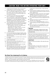
... this unit, and/or personal injury. - IMPORTANT Please record the serial number of power. We Want You Listening For A Lifetime YAMAHA and the Electronic Industries Association's Consumer Electronics Group want you to consume a very small quantity of this unit is designed to avoid ... THIS BEFORE OPERATING YOUR UNIT. away from loud sounds is turned off. MODEL: Serial No.: The serial number is too late, YAMAHA and the Electronic Industries Association's Consumer Electronics Group recommend you to obstruct heat radiation. Using this unit with a humidifier) to prevent ...
... this unit, and/or personal injury. - IMPORTANT Please record the serial number of power. We Want You Listening For A Lifetime YAMAHA and the Electronic Industries Association's Consumer Electronics Group want you to consume a very small quantity of this unit is designed to avoid ... THIS BEFORE OPERATING YOUR UNIT. away from loud sounds is turned off. MODEL: Serial No.: The serial number is too late, YAMAHA and the Electronic Industries Association's Consumer Electronics Group recommend you to obstruct heat radiation. Using this unit with a humidifier) to prevent ...
Owners Manual
Page 5
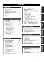
INTRODUCTION PREPARATION BASIC OPERATION CONTENTS INTRODUCTION FEATURES 2 GETTING STARTED 3 Supplied accessories 3 Installing batteries in the remote control 3 CONTROLS AND FUNCTIONS 4 Front panel 4 Remote control 6 Front panel display 8 Rear panel 10 PREPARATION CONNECTIONS 11 Placing speakers 11 Connecting speakers 12 Information on jacks and cable plugs 15 Audio and video signal flow 16 Connecting a TV 17 Connecting a DVD player, a DVD recorder, a VCR or an STB 18 Connecting a CD player, an MD player or a tape deck 20 Connecting a multi-format player or an external ...
INTRODUCTION PREPARATION BASIC OPERATION CONTENTS INTRODUCTION FEATURES 2 GETTING STARTED 3 Supplied accessories 3 Installing batteries in the remote control 3 CONTROLS AND FUNCTIONS 4 Front panel 4 Remote control 6 Front panel display 8 Rear panel 10 PREPARATION CONNECTIONS 11 Placing speakers 11 Connecting speakers 12 Information on jacks and cable plugs 15 Audio and video signal flow 16 Connecting a TV 17 Connecting a DVD player, a DVD recorder, a VCR or an STB 18 Connecting a CD player, an MD player or a tape deck 20 Connecting a multi-format player or an external ...
Owners Manual
Page 6
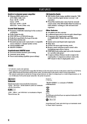
...front panel and the remote control, the button name on the remote control is given in parentheses. • This manual is a trademark of YAMAHA CORPORATION. Design and specifications are subject to change in part as the MP3 format) to that of a high-quality stereo Notes • y...THD, 1 kHz, 6 Ω) Front: 120 W + 120 W Center: 120 W Surround: 120 W + 120 W Subwoofer: 120 W (30 Hz, 6 Ω) Sound field features ◆ Proprietary YAMAHA technology for the creation of sound fields ◆ Dolby Digital decoder ◆ DTS, DTS Neo:6, DTS 96/24 decoder ◆ Dolby Pro Logic/Dolby Pro...
...front panel and the remote control, the button name on the remote control is given in parentheses. • This manual is a trademark of YAMAHA CORPORATION. Design and specifications are subject to change in part as the MP3 format) to that of a high-quality stereo Notes • y...THD, 1 kHz, 6 Ω) Front: 120 W + 120 W Center: 120 W Surround: 120 W + 120 W Subwoofer: 120 W (30 Hz, 6 Ω) Sound field features ◆ Proprietary YAMAHA technology for the creation of sound fields ◆ Dolby Digital decoder ◆ DTS, DTS Neo:6, DTS 96/24 decoder ◆ Dolby Pro Logic/Dolby Pro...
Owners Manual
Page 7
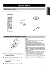
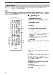
GETTING STARTED Remote control POWER POWER TV AV STANDBY POWER CD MD/CD-R TUNER XM DVD DTV/CBL DVR V-AUX REC DISC SKIP CODE SET MULTI CH IN SLEEP AMP TV VOL CH VOLUME MUTE INPUT MUTE STEREO 1 MUSIC ENTERTAIN MOVIE 2 3 4 STANDARD 5 SELECT 6 EXTD SUR. 7 DIRECT ST. 8 SPEAKERS 9 ENHANCER 0 NIGHT STRAIGHT 10 ENT. RETURN XM MEMORY PRESET/CH A-E/CAT. Read the packaging carefully as alkaline and manganese batteries) together. When the memory is without batteries for more than 2 minutes, or if exhausted batteries remain in the remote control 2 1 3 1 ...
GETTING STARTED Remote control POWER POWER TV AV STANDBY POWER CD MD/CD-R TUNER XM DVD DTV/CBL DVR V-AUX REC DISC SKIP CODE SET MULTI CH IN SLEEP AMP TV VOL CH VOLUME MUTE INPUT MUTE STEREO 1 MUSIC ENTERTAIN MOVIE 2 3 4 STANDARD 5 SELECT 6 EXTD SUR. 7 DIRECT ST. 8 SPEAKERS 9 ENHANCER 0 NIGHT STRAIGHT 10 ENT. RETURN XM MEMORY PRESET/CH A-E/CAT. Read the packaging carefully as alkaline and manganese batteries) together. When the memory is without batteries for more than 2 minutes, or if exhausted batteries remain in the remote control 2 1 3 1 ...
Owners Manual
Page 8
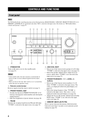
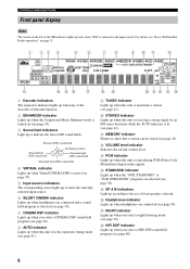
CONTROLS AND FUNCTIONS CONTROLS AND FUNCTIONS Front panel Note The XM Satellite Radio controlling functions in the following buttons (SEARCH MODE, CATEGORY, PRESET/TUNING/CH l / h, MEMORY, and DISPLAY) are operational only when "XM" is selected as the input source. The colon (:) is not selected as the input source (see page 33). 7 MEMORY (MAN'L/AUTO FM) Stores a preset station in the front panel display (see page 42). • Adjusts the level of the 8 preset station numbers (1 to the standby mode (see page 33). 6 PRESET/TUNING/CH l / h, LEVEL +/- Hold down this button for more than...
CONTROLS AND FUNCTIONS CONTROLS AND FUNCTIONS Front panel Note The XM Satellite Radio controlling functions in the following buttons (SEARCH MODE, CATEGORY, PRESET/TUNING/CH l / h, MEMORY, and DISPLAY) are operational only when "XM" is selected as the input source. The colon (:) is not selected as the input source (see page 33). 7 MEMORY (MAN'L/AUTO FM) Stores a preset station in the front panel display (see page 42). • Adjusts the level of the 8 preset station numbers (1 to the standby mode (see page 33). 6 PRESET/TUNING/CH l / h, LEVEL +/- Hold down this button for more than...
Owners Manual
Page 9
D TONE CONTROL Selects "BASS" or "TREBLE" to adjust the total balance of the front left and right speakers in conjunction with BASS/TREBLE +/- buttons (see page 59). G INPUT MODE Selects either digital or analog input signals exclusively or sets this unit (see page 8). 9 TUNING MODE (AUTO/MAN'L) Switches between automatic tuning (the AUTO indicator is turned on the remote control). F PROGRAM l / h buttons Selects sound field programs (see page 29). INTRODUCTION 8 Front panel display Shows information about the operational status of this unit to automatically detect the ...
D TONE CONTROL Selects "BASS" or "TREBLE" to adjust the total balance of the front left and right speakers in conjunction with BASS/TREBLE +/- buttons (see page 59). G INPUT MODE Selects either digital or analog input signals exclusively or sets this unit (see page 8). 9 TUNING MODE (AUTO/MAN'L) Switches between automatic tuning (the AUTO indicator is turned on the remote control). F PROGRAM l / h buttons Selects sound field programs (see page 29). INTRODUCTION 8 Front panel display Shows information about the operational status of this unit to automatically detect the ...
Owners Manual
Page 10
RETURN XM MEMORY PRESET/CH A-E/CAT. Press this unit 1 Press AMP to the standby mode (see page 38). - To operate other components, see page 24). 6 For details, see "XM Satellite Radio controls and functions" on page 49. ■ Controlling this button repeatedly to toggle as the input source. Aim this unit. Use EXTD SUR. CONTROLS AND FUNCTIONS Remote control This section describes the function of front speakers connected to the FRONT A and/or B terminals on the rear panel. LEVEL TITLE BAND SET MENU MENU SRCH MODE ENTER A-E/CAT. to play back 6.1-channel ...
RETURN XM MEMORY PRESET/CH A-E/CAT. Press this unit 1 Press AMP to the standby mode (see page 38). - To operate other components, see page 24). 6 For details, see "XM Satellite Radio controls and functions" on page 49. ■ Controlling this button repeatedly to toggle as the input source. Aim this unit. Use EXTD SUR. CONTROLS AND FUNCTIONS Remote control This section describes the function of front speakers connected to the FRONT A and/or B terminals on the rear panel. LEVEL TITLE BAND SET MENU MENU SRCH MODE ENTER A-E/CAT. to play back 6.1-channel ...
Owners Manual
Page 11
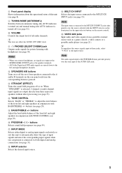
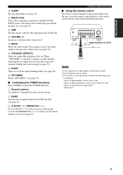
E VOLUME +/- G STRAIGHT (EFFECT) Turns the sound field programs off the night listening modes (see page 32). places of conditions: - dusty places 7 Increases or decreases the volume level. j / i, PRESET/CH u / d Press A-E/CAT. CONTROLS AND FUNCTIONS ■ Using the remote control The remote control transmits a directional infrared ray. Be sure to 8) (see page 45). places of high humidity, such as near a bath - C MULTI CH IN Selects the component connected to select preset stations. 7 BAND Switches the reception band between FM and AM (see page 30). STANDBY /ON PHONES...
E VOLUME +/- G STRAIGHT (EFFECT) Turns the sound field programs off the night listening modes (see page 32). places of conditions: - dusty places 7 Increases or decreases the volume level. j / i, PRESET/CH u / d Press A-E/CAT. CONTROLS AND FUNCTIONS ■ Using the remote control The remote control transmits a directional infrared ray. Be sure to 8) (see page 45). places of high humidity, such as near a bath - C MULTI CH IN Selects the component connected to select preset stations. 7 BAND Switches the reception band between FM and AM (see page 30). STANDBY /ON PHONES...
Owners Manual
Page 12
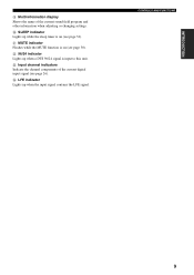
E SP A B indicators Light up according to show the currently selected input source. 6 SILENT CINEMA indicator Lights up when headphones are connected and a sound field program is selected (see page 30). 7 CINEMA DSP indicator Lights up when you select a night listening mode (see page 60). 8 ENHANCED" programs are connected (see page 43). F Headphones indicator Lights up when headphones are selected (see page 39). 5 Input source indicators The corresponding cursor lights up to indicate the active DSP sound fields. Presence DSP sound field Surround left of the XM indicator...
E SP A B indicators Light up according to show the currently selected input source. 6 SILENT CINEMA indicator Lights up when headphones are connected and a sound field program is selected (see page 30). 7 CINEMA DSP indicator Lights up when you select a night listening mode (see page 60). 8 ENHANCED" programs are connected (see page 43). F Headphones indicator Lights up when headphones are selected (see page 39). 5 Input source indicators The corresponding cursor lights up to indicate the active DSP sound fields. Presence DSP sound field Surround left of the XM indicator...
Owners Manual
Page 13
K MUTE indicator Flashes while the MUTE function is on (see page 32). L 96/24 indicator Lights up when the input signal contains the LFE signal. CONTROLS AND FUNCTIONS 9 J SLEEP indicator Lights up while the sleep timer is input to this unit. M Input channel indicators Indicate the channel components of the current sound field program and other information when adjusting or changing settings. N LFE indicator Lights up when a DTS 96/24 signal is on (see page 26). INTRODUCTION I Multi-information display Shows the name of the current digital input signal (see page 30).
K MUTE indicator Flashes while the MUTE function is on (see page 32). L 96/24 indicator Lights up when the input signal contains the LFE signal. CONTROLS AND FUNCTIONS 9 J SLEEP indicator Lights up while the sleep timer is input to this unit. M Input channel indicators Indicate the channel components of the current sound field program and other information when adjusting or changing settings. N LFE indicator Lights up when a DTS 96/24 signal is on (see page 26). INTRODUCTION I Multi-information display Shows the name of the current digital input signal (see page 30).
Owners Manual
Page 14
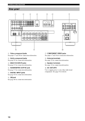
A FRONT SPEAKERS SURROUND B CENTER SUBWOOFER 7 COMPONENT VIDEO DVD DVR Y PB PR Y PB PR DTV/CBL AC OUTLETS MONITOR OUT 8 9 1 Video component jacks See pages 17 and 18 for connection information. 2 Audio component jacks See page 20 for connection information. 3 MULTI CH INPUT jacks See page 21 for connection information. 4 SUBWOOFER OUTPUT jack See page 13 for connection information. 5 DIGITAL INPUT jacks See page 18 for connection information. 6 XM jack See page 48 for connection information. 0 7 COMPONENT VIDEO jacks See pages 17 and 18 for connection information. 8 ...
A FRONT SPEAKERS SURROUND B CENTER SUBWOOFER 7 COMPONENT VIDEO DVD DVR Y PB PR Y PB PR DTV/CBL AC OUTLETS MONITOR OUT 8 9 1 Video component jacks See pages 17 and 18 for connection information. 2 Audio component jacks See page 20 for connection information. 3 MULTI CH INPUT jacks See page 21 for connection information. 4 SUBWOOFER OUTPUT jack See page 13 for connection information. 5 DIGITAL INPUT jacks See page 18 for connection information. 6 XM jack See page 48 for connection information. 0 7 COMPONENT VIDEO jacks See pages 17 and 18 for connection information. 8 ...
Owners Manual
Page 15
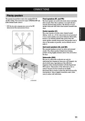
Center speaker (C) The center speaker is not practical to use a center speaker, you can use of the LFE (lowfrequency effect) channel included in Dolby Digital and DTS sources. If for some reason it is for hi-fi stereo reproduction of a subwoofer is better to enjoy CINEMA DSP and multi-channel audio sources. * ITU-R is not so critical, because low bass sounds are used for effect and surround sounds. The distance of the video monitor should be the same. Subwoofer (SW) The use it to place the subwoofer near the front speakers. Turn it . But it . Place these speakers...
Center speaker (C) The center speaker is not practical to use a center speaker, you can use of the LFE (lowfrequency effect) channel included in Dolby Digital and DTS sources. If for some reason it is for hi-fi stereo reproduction of a subwoofer is better to enjoy CINEMA DSP and multi-channel audio sources. * ITU-R is not so critical, because low bass sounds are used for effect and surround sounds. The distance of the video monitor should be the same. Subwoofer (SW) The use it to place the subwoofer near the front speakers. Turn it . But it . Place these speakers...
Owners Manual
Page 16
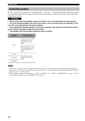
The impedance of each speaker must be 6 Ω or higher. Connect the striped (grooved, etc.) cable to connect the left channel (L), right channel (R), "+" (red) and "-" (black) properly. CAUTION • Before connecting the speakers, make sure that this unit is in "BASS OUT" (see page 24). • Do not let the bare speaker wires touch each speaker must be 4 Ω or higher. This could damage this unit and/or speakers. • Use magnetically shielded speakers. Connect the plain cable to the "-" (black) terminals. • The low-frequency signals of other or do not let ...
The impedance of each speaker must be 6 Ω or higher. Connect the striped (grooved, etc.) cable to connect the left channel (L), right channel (R), "+" (red) and "-" (black) properly. CAUTION • Before connecting the speakers, make sure that this unit is in "BASS OUT" (see page 24). • Do not let the bare speaker wires touch each speaker must be 4 Ω or higher. This could damage this unit and/or speakers. • Use magnetically shielded speakers. Connect the plain cable to the "-" (black) terminals. • The low-frequency signals of other or do not let ...
Owners Manual
Page 17
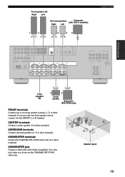
SUBWOOFER jack Connect a subwoofer with built in amplifier (6) to this jack when you use the YAMAHA SW-P3600 subwoofer. 1 2 3 6 4 5 Speaker layout 13 SUBWOOFER terminals Connect the YAMAHA SW-P3600 subwoofer (6) to these terminals. If you do not use only one or two front speaker systems (1, 2) to these terminals. Front speakers (A) Right Left ...
SUBWOOFER jack Connect a subwoofer with built in amplifier (6) to this jack when you use the YAMAHA SW-P3600 subwoofer. 1 2 3 6 4 5 Speaker layout 13 SUBWOOFER terminals Connect the YAMAHA SW-P3600 subwoofer (6) to these terminals. If you do not use only one or two front speaker systems (1, 2) to these terminals. Front speakers (A) Right Left ...
Owners Manual
Page 18
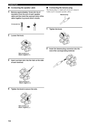
Banana plug 10 mm (0.4 in ) of insulation from the end of the cable together to prevent short circuits. ■ Connecting the banana plug The banana plug is a single-pole electrical connector widely used to secure the wire. Red: positive (+) Black: negative (-) 14 Red: positive (+) Black: negative (-) 4 Tighten the knob to terminate speaker cables. Red: positive (+) Black: negative (-) 2 Insert the banana plug connector into the end of the corresponding terminal. 3 Insert one bare wire into the hole on the side of each speaker cable and then twist the exposed wires of each terminal....
Banana plug 10 mm (0.4 in ) of insulation from the end of the cable together to prevent short circuits. ■ Connecting the banana plug The banana plug is a single-pole electrical connector widely used to secure the wire. Red: positive (+) Black: negative (-) 14 Red: positive (+) Black: negative (-) 4 Tighten the knob to terminate speaker cables. Red: positive (+) Black: negative (-) 2 Insert the banana plug connector into the end of the corresponding terminal. 3 Insert one bare wire into the hole on the side of each speaker cable and then twist the exposed wires of each terminal....
Owners Manual
Page 19
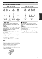
Connect red plugs to the right jacks and white plugs to put the cap back in place. PORTABLE jack For analog audio signals transmitted via optical digital audio cables. All digital input jacks are not using the optical jack, be sure to the left and right analog audio cables. DIGITAL AUDIO OPTICAL jacks For digital audio signals transmitted via stereo analog audio mini cables. When you are compatible with 96-kHz sampling digital signals. • Pull out the cap from dust. COMPONENT VIDEO jacks For component video signals, separated into the luminance (Y) and chrominance (PB, PR) ...
Connect red plugs to the right jacks and white plugs to put the cap back in place. PORTABLE jack For analog audio signals transmitted via optical digital audio cables. All digital input jacks are not using the optical jack, be sure to the left and right analog audio cables. DIGITAL AUDIO OPTICAL jacks For digital audio signals transmitted via stereo analog audio mini cables. When you are compatible with 96-kHz sampling digital signals. • Pull out the cap from dust. COMPONENT VIDEO jacks For component video signals, separated into the luminance (Y) and chrominance (PB, PR) ...
Owners Manual
Page 20
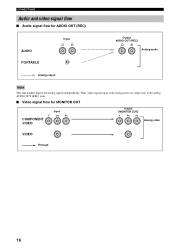
Thus, audio signals input at the analog jacks are output only at the analog AUDIO OUT (REC) jacks. ■ Video signal flow for AUDIO OUT (REC) AUDIO PORTABLE Input L R Output AUDIO OUT (REC) L R Analog audio Analog output Note This unit handles digital and analog signals independently. CONNECTIONS Audio and video signal flow ■ Audio signal flow for MONITOR OUT Input Y COMPONENT VIDEO PB PR Output (MONITOR OUT) Y PB PR Analog video VIDEO Through 16
Thus, audio signals input at the analog jacks are output only at the analog AUDIO OUT (REC) jacks. ■ Video signal flow for AUDIO OUT (REC) AUDIO PORTABLE Input L R Output AUDIO OUT (REC) L R Analog audio Analog output Note This unit handles digital and analog signals independently. CONNECTIONS Audio and video signal flow ■ Audio signal flow for MONITOR OUT Input Y COMPONENT VIDEO PB PR Output (MONITOR OUT) Y PB PR Analog video VIDEO Through 16