

Owners Manual
Page 1
U HTR-5560 AV Receiver OWNER'S MANUAL
U HTR-5560 AV Receiver OWNER'S MANUAL
Owners Manual
Page 2
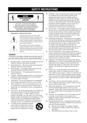
Do not use a mounting accessory recommended by the manufacturer. for future reference. in the operating instructions should be adhered to. Quick stops, excessive force, and uneven surfaces may fall into the power outlet only one blade wider than the other similar surface. Grounding or Polarization - Lightning - Unplug this product from the product. All warnings on or pinched by the product manufacturer as contact with care. Follow Instructions - Attachments - Do not use attachments not recommended by items placed upon or against them might be ...
Do not use a mounting accessory recommended by the manufacturer. for future reference. in the operating instructions should be adhered to. Quick stops, excessive force, and uneven surfaces may fall into the power outlet only one blade wider than the other similar surface. Grounding or Polarization - Lightning - Unplug this product from the product. All warnings on or pinched by the product manufacturer as contact with care. Follow Instructions - Attachments - Do not use attachments not recommended by items placed upon or against them might be ...
Owners Manual
Page 3
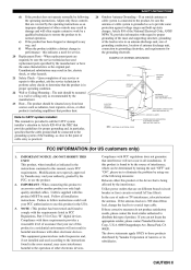
... controls may result in this product MUST be the source of interference, which can not locate the appropriate retailer, please contact Yamaha Electronics Corp., U.S.A. 6660 Orangethorpe Ave, Buena Park, CA 90620. The product should be sure the antenna or cable system is...results, please contact the local retailer authorized to eliminate the problem by Yamaha Corporation of product. PART H) NEC - IMPORTANT NOTICE : DO NOT MODIFY THIS UNIT! Modifications not expressly approved by Yamaha may cause interference harmful to grounding electrodes, and requirements for proper ...
... controls may result in this product MUST be the source of interference, which can not locate the appropriate retailer, please contact Yamaha Electronics Corp., U.S.A. 6660 Orangethorpe Ave, Buena Park, CA 90620. The product should be sure the antenna or cable system is...results, please contact the local retailer authorized to eliminate the problem by Yamaha Corporation of product. PART H) NEC - IMPORTANT NOTICE : DO NOT MODIFY THIS UNIT! Modifications not expressly approved by Yamaha may cause interference harmful to grounding electrodes, and requirements for proper ...
Owners Manual
Page 4
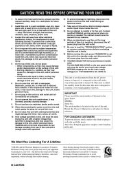
...Do not use force on the rear panel of this unit in them, as they may overheat, possibly causing damage. this manual carefully. YAMAHA will not be opened for future reference. vacation), disconnect the AC power plug from direct sunlight, heat sources, vibration, dust, moisture, and...inside this unit in a environment with liquid in the space below. Before moving this unit, and/or personal injury. Contact qualified YAMAHA service personnel when any damage resulting from use this unit itself is called the standby mode. Be sure to this unit, press ...
...Do not use force on the rear panel of this unit in them, as they may overheat, possibly causing damage. this manual carefully. YAMAHA will not be opened for future reference. vacation), disconnect the AC power plug from direct sunlight, heat sources, vibration, dust, moisture, and...inside this unit in a environment with liquid in the space below. Before moving this unit, and/or personal injury. Contact qualified YAMAHA service personnel when any damage resulting from use this unit itself is called the standby mode. Be sure to this unit, press ...
Owners Manual
Page 5
RANGE (dynamic range) ...44 5 L/R BALANCE (balance of CINEMA-DSP ...30 CINEMA-DSP programs ...32 TUNING ...34 Automatic and manual tuning ...34 Presetting stations ...35 Tuning in the remote control ...3 ADVANCED OPERATION SET MENU ...40 Adjusting the items on the SET MENU ...40 1 SPEAKER SET (speaker mode settings) ...41 2 LFE LEVEL ...43 3 SP DLY TIME (speaker delay time) ...43 4 D. GUARD (memory guard) ...45 INTRODUCTION CONTROLS AND FUNCTIONS ...4 Front panel ...4 Remote control ...6 Using the remote control ...7 Front panel display ...8 PREPARATION PREPARATION SPEAKER SETUP ...9 ...
RANGE (dynamic range) ...44 5 L/R BALANCE (balance of CINEMA-DSP ...30 CINEMA-DSP programs ...32 TUNING ...34 Automatic and manual tuning ...34 Presetting stations ...35 Tuning in the remote control ...3 ADVANCED OPERATION SET MENU ...40 Adjusting the items on the SET MENU ...40 1 SPEAKER SET (speaker mode settings) ...41 2 LFE LEVEL ...43 3 SP DLY TIME (speaker delay time) ...43 4 D. GUARD (memory guard) ...45 INTRODUCTION CONTROLS AND FUNCTIONS ...4 Front panel ...4 Remote control ...6 Using the remote control ...7 Front panel display ...8 PREPARATION PREPARATION SPEAKER SETUP ...9 ...

Owners Manual
Page 6
... sound field processing N N N N Dolby Pro Logic/Dolby Pro Logic decoder Dolby Digital/Dolby Digital EX decoder DTS/DTS-ES compatible decoder CINEMA DSP: Combination of YAMAHA DSP technology and Dolby Pro Logic, Dolby Digital or DTS N Virtual CINEMA DSP N SILENT CINEMA DSP Sophisticated AM/FM Tuner N 40-Station random access preset...
... sound field processing N N N N Dolby Pro Logic/Dolby Pro Logic decoder Dolby Digital/Dolby Digital EX decoder DTS/DTS-ES compatible decoder CINEMA DSP: Combination of YAMAHA DSP technology and Dolby Pro Logic, Dolby Digital or DTS N Virtual CINEMA DSP N SILENT CINEMA DSP Sophisticated AM/FM Tuner N 40-Station random access preset...
Owners Manual
Page 7
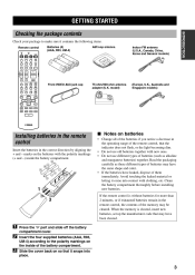
MUTE ROCK CONCERT ENTERTAINMENT HALL JAZZ CLUB 1 TV SPORTS 2 MONO MOVIE 3 MOVIE THEATER 1 4 MOVIE THEATER 2 Front VIDEO AUX jack cap 5 /DTS SUR. 6 7 8 75-ohm/300-ohm antenna adapter (U.K. Clean the battery compartment thoroughly before installing new batteries. Insert the four supplied batteries (AAA, R03, UM-4) according to make sure it come into place. When the memory is without batteries for more than 2 minutes, or if exhausted batteries remain in the remote control, the contents of the battery compartment. Slide the cover back on so that may have leaked, dispose ...
MUTE ROCK CONCERT ENTERTAINMENT HALL JAZZ CLUB 1 TV SPORTS 2 MONO MOVIE 3 MOVIE THEATER 1 4 MOVIE THEATER 2 Front VIDEO AUX jack cap 5 /DTS SUR. 6 7 8 75-ohm/300-ohm antenna adapter (U.K. Clean the battery compartment thoroughly before installing new batteries. Insert the four supplied batteries (AAA, R03, UM-4) according to make sure it come into place. When the memory is without batteries for more than 2 minutes, or if exhausted batteries remain in the remote control, the contents of the battery compartment. Slide the cover back on so that may have leaked, dispose ...
Owners Manual
Page 8
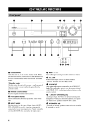
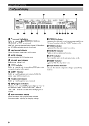
This does not affect the OUT (REC) level. 7 6CH INPUT Selects the audio source connected to or watch. 6 VOLUME Controls the output level of input signals (AUTO, DTS, ANALOG) to two or more input jacks. This audio takes priority over the source selected with headphones. Standby mode In this mode, this unit will be set it to the standby mode. Priority cannot be a 4 to 5-second delay before this unit on or off. 4 INPUT MODE Sets the priority for private listening with INPUT l / h (or the input selector buttons on the remote control). 2 Remote control sensor Receives signals ...
This does not affect the OUT (REC) level. 7 6CH INPUT Selects the audio source connected to or watch. 6 VOLUME Controls the output level of input signals (AUTO, DTS, ANALOG) to two or more input jacks. This audio takes priority over the source selected with headphones. Standby mode In this mode, this unit will be set it to the standby mode. Priority cannot be a 4 to 5-second delay before this unit on or off. 4 INPUT MODE Sets the priority for private listening with INPUT l / h (or the input selector buttons on the remote control). 2 Remote control sensor Receives signals ...
Owners Manual
Page 9
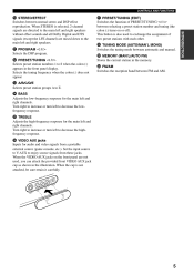
u PRESET/TUNING (EDIT) Switches the function of two preset stations with each other. PREPARATION e A/B/C/D/E Selects preset station groups A to exchange the assignment of PRESET/TUNING l / h between automatic and manual. When the VIDEO AUX jacks on or off). BASIC OPERATION t TREBLE Adjusts the high-frequency response for the main left and right channels. When the cap is also used , you can attach the provided front VIDEO AUX jack cap as shown in the illustration. E VID UX O A ADDITIONAL INFORMATION AL TIC OP AU DIO R L EO VID IDEO SV APPENDIX English 5 o MEMORY (MAN...
u PRESET/TUNING (EDIT) Switches the function of two preset stations with each other. PREPARATION e A/B/C/D/E Selects preset station groups A to exchange the assignment of PRESET/TUNING l / h between automatic and manual. When the VIDEO AUX jacks on or off). BASIC OPERATION t TREBLE Adjusts the high-frequency response for the main left and right channels. When the cap is also used , you can attach the provided front VIDEO AUX jack cap as shown in the illustration. E VID UX O A ADDITIONAL INFORMATION AL TIC OP AU DIO R L EO VID IDEO SV APPENDIX English 5 o MEMORY (MAN...
Owners Manual
Page 10
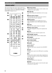
Aim this unit. TUNER SLEEP 3 DVD D-TV/CBL V-AUX 6CH INPUT VCR 1 VCR2/DVR A q w AMP 4 DSP program Select DSP programs for controlling this window at the component you want to operate. 2 CODE SET Used when setting up the manufacturer code (see page 47). 1 2 CODE SET 8 TRANSMIT SYSTEM 9 0 POWER TV CD POWER AV MD/CD-R STANDBY POWER 3 Input selector buttons Select the input source and set the remote control to operate the selected source component. TV INPUT - e AMP Sets the remote control to the AMP mode for the AMP position. r Å Sets the remote control to operate ...
Aim this unit. TUNER SLEEP 3 DVD D-TV/CBL V-AUX 6CH INPUT VCR 1 VCR2/DVR A q w AMP 4 DSP program Select DSP programs for controlling this window at the component you want to operate. 2 CODE SET Used when setting up the manufacturer code (see page 47). 1 2 CODE SET 8 TRANSMIT SYSTEM 9 0 POWER TV CD POWER AV MD/CD-R STANDBY POWER 3 Input selector buttons Select the input source and set the remote control to operate the selected source component. TV INPUT - e AMP Sets the remote control to the AMP mode for the AMP position. r Å Sets the remote control to operate ...

Owners Manual
Page 11
dusty places; in the following types of conditions: - SILENT SPEAKERS A B STEREO PROGRAM PRESET/TUNING A/B/C/D/E EFFECT PHONES - + - + S VIDEO VIDEO L AUDIO R OPTICAL 30° VCR 1 VCR2/DVR 30° Approximately 6 m (20 feet) PREPARATION BASIC OPERATION The remote control transmits a directional infrared beam. ADVANCED OPERATION ADDITIONAL INFORMATION APPENDIX English 7 high humidity or temperature such as near a heater, stove or bath; - or - When STEREO is selected, 2-channel signals are directed to the main left and right speakers without effect ...
dusty places; in the following types of conditions: - SILENT SPEAKERS A B STEREO PROGRAM PRESET/TUNING A/B/C/D/E EFFECT PHONES - + - + S VIDEO VIDEO L AUDIO R OPTICAL 30° VCR 1 VCR2/DVR 30° Approximately 6 m (20 feet) PREPARATION BASIC OPERATION The remote control transmits a directional infrared beam. ADVANCED OPERATION ADDITIONAL INFORMATION APPENDIX English 7 high humidity or temperature such as near a heater, stove or bath; - or - When STEREO is selected, 2-channel signals are directed to the main left and right speakers without effect ...
Owners Manual
Page 12
Lights up when this unit is selected. 9 Multi-information display Shows the current DSP program name and other information when adjusting or changing settings. 8 t Input channel indicator Indicates the channel components of the selected DSP program lights up when the ENTERTAINMENT, MOVIE THEATER 1, MOVIE THEATER 2 or V/DTS SURROUND DSP program is reproducing PCM (pulse code modulation) digital audio signals. w MEMORY indicator Flashes to a station. 2 Input source indicator Shows the current input source with a cursor. e AUTO indicator Shows that this unit is tuned to show ...
Lights up when this unit is selected. 9 Multi-information display Shows the current DSP program name and other information when adjusting or changing settings. 8 t Input channel indicator Indicates the channel components of the selected DSP program lights up when the ENTERTAINMENT, MOVIE THEATER 1, MOVIE THEATER 2 or V/DTS SURROUND DSP program is reproducing PCM (pulse code modulation) digital audio signals. w MEMORY indicator Flashes to a station. 2 Input source indicator Shows the current input source with a cursor. e AUTO indicator Shows that this unit is tuned to show ...
Owners Manual
Page 13
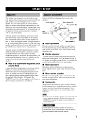
... equal distance from the floor as the rear speakers. ADVANCED OPERATION I Subwoofer The position of speakers still creates the interference with the main speakers. The YAMAHA Active Servo Processing Subwoofer System is also possible to further expand your sound field It is ideal for reproducing the LFE (low-frequency effect) channel...
... equal distance from the floor as the rear speakers. ADVANCED OPERATION I Subwoofer The position of speakers still creates the interference with the main speakers. The YAMAHA Active Servo Processing Subwoofer System is also possible to further expand your sound field It is ideal for reproducing the LFE (low-frequency effect) channel...

Owners Manual
Page 14
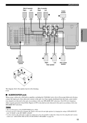
This could damage this unit. I Connecting to these terminals. 10 Insert one speaker system, it can be connected to the SPEAKERS terminals Red: positive (+) Black: negative (-) 2 1 3 1 2 3 Unscrew the knob. model) y Banana plug (U.S.A., Canada, Australia, China, Korea and General models) • Banana plug connections are faulty, no sound will be heard from each of each other or any metal part of insulated cables running side by side. model) I REAR SPEAKERS terminals A rear speaker system can be connected to these terminals. When using only one bare wire into the ...
This could damage this unit. I Connecting to these terminals. 10 Insert one speaker system, it can be connected to the SPEAKERS terminals Red: positive (+) Black: negative (-) 2 1 3 1 2 3 Unscrew the knob. model) y Banana plug (U.S.A., Canada, Australia, China, Korea and General models) • Banana plug connections are faulty, no sound will be heard from each of each other or any metal part of insulated cables running side by side. model) I REAR SPEAKERS terminals A rear speaker system can be connected to these terminals. When using only one bare wire into the ...
Owners Manual
Page 15
... BASIC OPERATION 4 Subwoofer system 5 Right 6 Left 7 ADVANCED OPERATION Rear speaker Rear center speaker 3 2 1 4 ADDITIONAL INFORMATION 5 7 6 The diagram shows the speaker layout in amplifier, including the YAMAHA Active Servo Processing Subwoofer System, connect the input jack of SPEAKER SET item "1E BASS" on the SET MENU to MAIN. • Use the control...
... BASIC OPERATION 4 Subwoofer system 5 Right 6 Left 7 ADVANCED OPERATION Rear speaker Rear center speaker 3 2 1 4 ADDITIONAL INFORMATION 5 7 6 The diagram shows the speaker layout in amplifier, including the YAMAHA Active Servo Processing Subwoofer System, connect the input jack of SPEAKER SET item "1E BASS" on the SET MENU to MAIN. • Use the control...
Owners Manual
Page 16
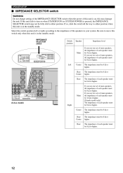
IMPEDANCE SELECTOR switch Switch position Speaker Impedance level Main MAIN A OR B :4 MIN. /SPEAKER A+B :8 MIN. /SPEAKER CENTER :6 MIN. /SPEAKER REAR CENTER :6 MIN. /SPEAKER REAR :6 MIN. /SPEAKER MAIN A OR B: 8 A+B:16 : 8 CENTER REAR CENTER: 8 : 8 REAR SET BEFORE POWER ON MIN. /SPEAKER MIN. /SPEAKER MIN. /SPEAKER MIN. /SPEAKER MIN. /SPEAKER If you use one set of main speakers, the impedance of each speaker must be 8 Ω or higher. The impedance must be 6 Ω or higher. If you use one set of main speakers, the impedance of each speaker must be 4 Ω or higher...
IMPEDANCE SELECTOR switch Switch position Speaker Impedance level Main MAIN A OR B :4 MIN. /SPEAKER A+B :8 MIN. /SPEAKER CENTER :6 MIN. /SPEAKER REAR CENTER :6 MIN. /SPEAKER REAR :6 MIN. /SPEAKER MAIN A OR B: 8 A+B:16 : 8 CENTER REAR CENTER: 8 : 8 REAR SET BEFORE POWER ON MIN. /SPEAKER MIN. /SPEAKER MIN. /SPEAKER MIN. /SPEAKER MIN. /SPEAKER If you use one set of main speakers, the impedance of each speaker must be 8 Ω or higher. The impedance must be 6 Ω or higher. If you use one set of main speakers, the impedance of each speaker must be 4 Ω or higher...
Owners Manual
Page 17
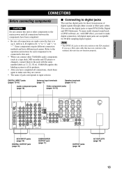
YAMAHA applies this unit conform to the EIA standard. All digital input jacks are acceptable for direct transmission of digital signals through either coaxial or fiber ... OUT (REC) MD /CD-R IN (PLAY) OUT GND VCR 1 DVD IN 75 UNBAL. CONNECTIONS Before connecting components CAUTION Do not connect this unit or other YAMAHA audio components (such as !, #, $ etc. COAXIAL OPTICAL D-TV/CBL - -
YAMAHA applies this unit conform to the EIA standard. All digital input jacks are acceptable for direct transmission of digital signals through either coaxial or fiber ... OUT (REC) MD /CD-R IN (PLAY) OUT GND VCR 1 DVD IN 75 UNBAL. CONNECTIONS Before connecting components CAUTION Do not connect this unit or other YAMAHA audio components (such as !, #, $ etc. COAXIAL OPTICAL D-TV/CBL - -
Owners Manual
Page 18
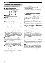
When using the video jacks of the component video jacks may differ depending on this unit. 14 I Connecting a video monitor Connect the video input jack on your component to the DIGITAL INPUT jack and connect the video signal output jack on the component to the VIDEO jack on this unit to play a source from your video monitor using this unit. If the power is off, this unit may distort the sound from AUDIO jacks. Then connect AUDIO jacks on your video component to the AUDIO OUT jacks and connect the video signal input jack on the video component to the VIDEO OUT jack on the ...
When using the video jacks of the component video jacks may differ depending on this unit. 14 I Connecting a video monitor Connect the video input jack on your component to the DIGITAL INPUT jack and connect the video signal output jack on the component to the VIDEO jack on this unit to play a source from your video monitor using this unit. If the power is off, this unit may distort the sound from AUDIO jacks. Then connect AUDIO jacks on your video component to the AUDIO OUT jacks and connect the video signal input jack on the video component to the VIDEO OUT jack on the ...
Owners Manual
Page 19
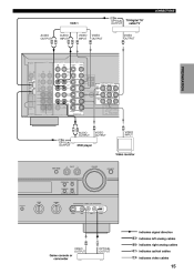
CONNECTIONS O VCR 1 OPTICAL OUTPUT TV/digital TV/ cable TV INTRODUCTION AUDIO OUTPUT L R AUDIO INPUT L R V VIDEO INPUT V VIDEO OUTPUT V VIDEO OUTPUT DIGITAL INPUT AUDIO R AUDIO L OUT VIDEO S VIDEO VIDEO PREPARATION CD CD R L VCR 2 /VDR IN TUNER AM ANT COAXIAL OPTICAL D-TV/CBL DVD OUT (REC) MD /CD-R IN (PLAY) OUT GND VCR 1 DVD IN 75 UNBAL. D-TV /CBL COMPONENT VIDEO PR/CR PB/CB Y MD/CD-R MAIN D-TV /CBL FM ANT MONITOR OUT BASIC OPERATION SURROUND DVD MD/CD-R OPTICAL SUB WOOFER CENTER DIGITAL OUTPUT 6CH INPUT SUB WOOFER S VIDEO OUTPUT VIDEO MONITOR OUT MAIN A OR B ...
CONNECTIONS O VCR 1 OPTICAL OUTPUT TV/digital TV/ cable TV INTRODUCTION AUDIO OUTPUT L R AUDIO INPUT L R V VIDEO INPUT V VIDEO OUTPUT V VIDEO OUTPUT DIGITAL INPUT AUDIO R AUDIO L OUT VIDEO S VIDEO VIDEO PREPARATION CD CD R L VCR 2 /VDR IN TUNER AM ANT COAXIAL OPTICAL D-TV/CBL DVD OUT (REC) MD /CD-R IN (PLAY) OUT GND VCR 1 DVD IN 75 UNBAL. D-TV /CBL COMPONENT VIDEO PR/CR PB/CB Y MD/CD-R MAIN D-TV /CBL FM ANT MONITOR OUT BASIC OPERATION SURROUND DVD MD/CD-R OPTICAL SUB WOOFER CENTER DIGITAL OUTPUT 6CH INPUT SUB WOOFER S VIDEO OUTPUT VIDEO MONITOR OUT MAIN A OR B ...
Owners Manual
Page 20
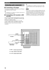
y • The AUDIO jacks are available for an CD recorder or MD recorder which does not have connected a recording component to the DIGITAL OUTPUT MD/ CD-R jack for digital recording. Connect the optical digital output jack on your CD recorder or MD recorder to the DIGITAL INPUT MD/ CD-R jack to the DIGITAL INPUT CD jack. CONNECTIONS Connecting audio components I Connecting a CD recorder or MD recorder Connect the optical digital signal input jack on your CD recorder or MD recorder to this unit, keep its power turned on while using this unit may distort the sound from OUT (...
y • The AUDIO jacks are available for an CD recorder or MD recorder which does not have connected a recording component to the DIGITAL OUTPUT MD/ CD-R jack for digital recording. Connect the optical digital output jack on your CD recorder or MD recorder to the DIGITAL INPUT MD/ CD-R jack to the DIGITAL INPUT CD jack. CONNECTIONS Connecting audio components I Connecting a CD recorder or MD recorder Connect the optical digital signal input jack on your CD recorder or MD recorder to this unit, keep its power turned on while using this unit may distort the sound from OUT (...