Owners Manual
Page 5
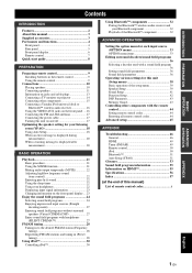
...11 Information on jacks and cable plugs 13 Connecting a TV monitor or projector 14 Connecting other components 15 Connecting a Yamaha iPod universal dock or Bluetooth™ wireless audio receiver 16 Using the VIDEO AUX jacks on the front panel .... 16 Connecting the FM and AM antennas 17 Connecting ... the remote control 44 Setting remote control codes 44 Resetting all remote control codes 44 Advanced setup 45 APPENDIX Troubleshooting 46 General 46 HDMI 49 Tuner (FM/AM 49 Remote control 50 iPod 50 Bluetooth 51 Auto Setup (YPAO 51 Glossary 53 Sound field program information ...
...11 Information on jacks and cable plugs 13 Connecting a TV monitor or projector 14 Connecting other components 15 Connecting a Yamaha iPod universal dock or Bluetooth™ wireless audio receiver 16 Using the VIDEO AUX jacks on the front panel .... 16 Connecting the FM and AM antennas 17 Connecting ... the remote control 44 Setting remote control codes 44 Resetting all remote control codes 44 Advanced setup 45 APPENDIX Troubleshooting 46 General 46 HDMI 49 Tuner (FM/AM 49 Remote control 50 iPod 50 Bluetooth 51 Auto Setup (YPAO 51 Glossary 53 Sound field program information ...
Owners Manual
Page 6
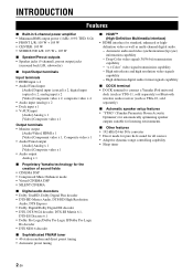
...terminal to connect a Yamaha iPod universal dock (such as YDS-11, sold separately) or Bluetooth wireless audio receiver (such as YBA-10, sold separately) ■ Automatic speaker setup features • "YPAO" (Yamaha Parametric Room Acoustic Optimizer)...105 W + 105 W ■ Speaker/Preout outputs • Speaker jacks (5-channel), preout output jacks (surround back L/R, subwoofer) ■ Input/Output terminals Input terminals • HDMI input x 4 • Audio/Visual input [Audio] Digital input (coaxial) x 2, digital input (optical) x 2, analog input x 2 [Video] Component video x 2, ...
...terminal to connect a Yamaha iPod universal dock (such as YDS-11, sold separately) or Bluetooth wireless audio receiver (such as YBA-10, sold separately) ■ Automatic speaker setup features • "YPAO" (Yamaha Parametric Room Acoustic Optimizer)...105 W + 105 W ■ Speaker/Preout outputs • Speaker jacks (5-channel), preout output jacks (surround back L/R, subwoofer) ■ Input/Output terminals Input terminals • HDMI input x 4 • Audio/Visual input [Audio] Digital input (coaxial) x 2, digital input (optical) x 2, analog input x 2 [Video] Component video x 2, ...

Owners Manual
Page 7
...trademark of Sony Corporation. INTRODUCTION PREPARATION About this manual for your operation. • Some operations can be performed by Yamaha in parentheses. • This manual is printed prior to production. Design and specifications are trademarks of Dolby Laboratories Manufactured... Rights Reserved. "HDMI," the "HDMI" logo and "High-Definition Multimedia Interface" are trademark of differences between the front panel and the remote control, the key name on the remote control. Supplied accessories Check that you received all of Yamaha Corporation. Manufactured under...
...trademark of Sony Corporation. INTRODUCTION PREPARATION About this manual for your operation. • Some operations can be performed by Yamaha in parentheses. • This manual is printed prior to production. Design and specifications are trademarks of Dolby Laboratories Manufactured... Rights Reserved. "HDMI," the "HDMI" logo and "High-Definition Multimedia Interface" are trademark of differences between the front panel and the remote control, the key name on the remote control. Supplied accessories Check that you received all of Yamaha Corporation. Manufactured under...
Owners Manual
Page 8
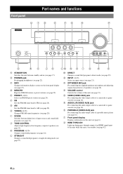
...output cable of a camcorder or game console (see page 22). Part names and functions Front panel UTD E FG H P STANDBY /ON PHONES SILENT CINEMA HDMI THROUGH INFO MEMORY l PRESET h FM BD/DVD SCENE TV CD AM RADIO l TUNING h TONE CONTROL PROGRAM l h STRAIGHT EFFECT DIRECT INPUT OPTIMIZER MIC... (see page 21). O OPTIMIZER MIC jack For connecting the supplied optimizer microphone and adjusting output characteristics of an HDMI signal input to straight decoding mode (see page 18). T Front panel display Displays information on the front panel display (see page...
...output cable of a camcorder or game console (see page 22). Part names and functions Front panel UTD E FG H P STANDBY /ON PHONES SILENT CINEMA HDMI THROUGH INFO MEMORY l PRESET h FM BD/DVD SCENE TV CD AM RADIO l TUNING h TONE CONTROL PROGRAM l h STRAIGHT EFFECT DIRECT INPUT OPTIMIZER MIC... (see page 21). O OPTIMIZER MIC jack For connecting the supplied optimizer microphone and adjusting output characteristics of an HDMI signal input to straight decoding mode (see page 18). T Front panel display Displays information on the front panel display (see page...

Owners Manual
Page 9
... MONITOR OUT HDMI 3 HDMI 4 FRONT SPEAKERS CENTER SURROUND OPTICAL ( TV ) AV 1 COAXIAL AV 2 COAXIAL (CD) AV 3 OPTICAL AV 4 AV 5 AV 6 AV OUT AUDIO1 AUDIO2 AUDIO OUT SURROUND BACK SUBWOOFER PRE OUT e fg hi j a DOCK terminal For connecting an optional Yamaha iPod universal dock (YDS11) or Bluetooth wireless audio receiver (YBA-10) (see page 15). b HDMI OUT/HDMI 1-4 For connecting an HDMI-compatible video monitor...
... MONITOR OUT HDMI 3 HDMI 4 FRONT SPEAKERS CENTER SURROUND OPTICAL ( TV ) AV 1 COAXIAL AV 2 COAXIAL (CD) AV 3 OPTICAL AV 4 AV 5 AV 6 AV OUT AUDIO1 AUDIO2 AUDIO OUT SURROUND BACK SUBWOOFER PRE OUT e fg hi j a DOCK terminal For connecting an optional Yamaha iPod universal dock (YDS11) or Bluetooth wireless audio receiver (YBA-10) (see page 15). b HDMI OUT/HDMI 1-4 For connecting an HDMI-compatible video monitor...

Owners Manual
Page 10
... Cursor indicators Light up when a sound field program that uses CINEMA DSP is activated (see page 28). d SLEEP indicator Lights up while receiving a radio broadcast signal from which signals are available for the current operation. h Multi information display Displays menu items and settings for operations. ...MUTE SW L CR SL SR SBL SB SBR g i 6 En Part names and functions Front panel display a b c STEREO TUNED g h a HDMI indicator Lights up during normal communication when HDMI is muted. f MUTE indicator Flashes when audio is selected as an input source.
... Cursor indicators Light up when a sound field program that uses CINEMA DSP is activated (see page 28). d SLEEP indicator Lights up while receiving a radio broadcast signal from which signals are available for the current operation. h Multi information display Displays menu items and settings for operations. ...MUTE SW L CR SL SR SBL SB SBR g i 6 En Part names and functions Front panel display a b c STEREO TUNED g h a HDMI indicator Lights up during normal communication when HDMI is muted. f MUTE indicator Flashes when audio is selected as an input source.
Owners Manual
Page 11
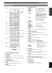
... PREPARATION BASIC OPERATION ADVANCED OPERATION Remote control a d g h i j k l n r TRANSMIT CODE SET POWER SOURCE 1 1 5 SLEEP POWER HDMI 2 3 4 AV 2 3 4 AUDIO 6 1 2 V-AUX [ A ] [ B ] DOCK TUNER FM AM PRESET TUNING INFO MEMORY MOVIE ENHANCER SUR. Selects ...n / l / h Select menu items displayed on and off . ADDITIONAL INFORMATION APPENDIX English 7 En Selects a Yamaha iPod universal dock/ Bluetooth wireless audio receiver connected to the previous screen or ends the menu screen. q MUTE Turns the mute function of external components (see...
... PREPARATION BASIC OPERATION ADVANCED OPERATION Remote control a d g h i j k l n r TRANSMIT CODE SET POWER SOURCE 1 1 5 SLEEP POWER HDMI 2 3 4 AV 2 3 4 AUDIO 6 1 2 V-AUX [ A ] [ B ] DOCK TUNER FM AM PRESET TUNING INFO MEMORY MOVIE ENHANCER SUR. Selects ...n / l / h Select menu items displayed on and off . ADDITIONAL INFORMATION APPENDIX English 7 En Selects a Yamaha iPod universal dock/ Bluetooth wireless audio receiver connected to the previous screen or ends the menu screen. q MUTE Turns the mute function of external components (see...
Owners Manual
Page 12
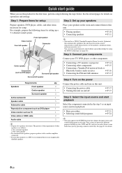
...8226; Connecting a TV monitor or projector ☞P. 14 • Connecting other components ☞P. 15 • Connecting a Yamaha iPod universal dock or Bluetooth wireless audio receiver ☞P. 16 • Connecting the FM and AM antennas ☞P. 17 Step 4: Turn on the power Connect the power... unit based on operations and settings. See the related pages for front). Center speaker Components (such as TV 1 Video cable or HDMI cable 2 Audio cable 2 y • Prepare two speakers (for details on room acoustic characteristics (audio characteristics of other speakers is...
...8226; Connecting a TV monitor or projector ☞P. 14 • Connecting other components ☞P. 15 • Connecting a Yamaha iPod universal dock or Bluetooth wireless audio receiver ☞P. 16 • Connecting the FM and AM antennas ☞P. 17 Step 4: Turn on the power Connect the power... unit based on operations and settings. See the related pages for front). Center speaker Components (such as TV 1 Video cable or HDMI cable 2 Audio cable 2 y • Prepare two speakers (for details on room acoustic characteristics (audio characteristics of other speakers is...

Owners Manual
Page 15
... a surround back channel. To obtain the balanced sound during playback, set the speaker output characteristics in advance using the Yamaha Parametric Room Acoustic Optimize (YPAO, see page 39). INTRODUCTION PREPARATION BASIC OPERATION Connections Connecting speakers When you to create the... page 18) or "Speaker Setup" of the external amplifier. ADVANCED OPERATION ADDITIONAL INFORMATION APPENDIX English 11 En ba c DMI 3 HDMI 4 FRONT SPEAKERS CENTER SURROUND Connecting the surround back speakers Connecting an external amplifier to the SURROUND BACK L/R jacks of the PRE OUT...
... a surround back channel. To obtain the balanced sound during playback, set the speaker output characteristics in advance using the Yamaha Parametric Room Acoustic Optimize (YPAO, see page 39). INTRODUCTION PREPARATION BASIC OPERATION Connections Connecting speakers When you to create the... page 18) or "Speaker Setup" of the external amplifier. ADVANCED OPERATION ADDITIONAL INFORMATION APPENDIX English 11 En ba c DMI 3 HDMI 4 FRONT SPEAKERS CENTER SURROUND Connecting the surround back speakers Connecting an external amplifier to the SURROUND BACK L/R jacks of the PRE OUT...

Owners Manual
Page 17
... composite video signals. To transmit optical digital audio signals. Use optical fiber cables for components that you use a commercially available 19-pin HDMI cable no longer than 5 meters (16 feet) with a COMPONENT VIDEO output signal are connecting. ■ Audio jacks ■ Video... both VIDEO jack and COMPONENT VIDEO jack in MONITOR OUT for digital audio signals. To transmit coaxial digital audio signals. HDMI jacks HDMI HDMI To transmit digital video and digital audio signals. ADVANCED OPERATION ADDITIONAL INFORMATION APPENDIX English 13 En Use jacks and cables appropriate...
... composite video signals. To transmit optical digital audio signals. Use optical fiber cables for components that you use a commercially available 19-pin HDMI cable no longer than 5 meters (16 feet) with a COMPONENT VIDEO output signal are connecting. ■ Audio jacks ■ Video... both VIDEO jack and COMPONENT VIDEO jack in MONITOR OUT for digital audio signals. To transmit coaxial digital audio signals. HDMI jacks HDMI HDMI To transmit digital video and digital audio signals. ADVANCED OPERATION ADDITIONAL INFORMATION APPENDIX English 13 En Use jacks and cables appropriate...

Owners Manual
Page 18
... terminal are output from the composite video output terminal. FM GND AM O OPTICAL ( TV ) AV 1 COAXIAL AV 2 COAXIAL (CD) AV 3 OPTICAL AV 4 AV 5 AV 6 AV OUT AUDIO1 14 En Note • When you use the AV input 1. TV, or projector (BD/DVD) HDMI OUT HDMI 1 HDMI 2 HD ANTENNA COMPONENT VIDEO UNBAL. If the TV supports an optical digital output, we recommend...
... terminal are output from the composite video output terminal. FM GND AM O OPTICAL ( TV ) AV 1 COAXIAL AV 2 COAXIAL (CD) AV 3 OPTICAL AV 4 AV 5 AV 6 AV OUT AUDIO1 14 En Note • When you use the AV input 1. TV, or projector (BD/DVD) HDMI OUT HDMI 1 HDMI 2 HD ANTENNA COMPONENT VIDEO UNBAL. If the TV supports an optical digital output, we recommend...

Owners Manual
Page 19
... ) AV 1 COAXIAL AV 2 COAXIAL (CD) AV 3 OPTICAL AV 4 AV 5 AV 6 AV OUT AUDIO1 AUDIO2 AUDIO OUT HDMI input (HDMI 1-4) CE Audio output (AUDIO OUT) Audio input (AUDIO 1-2) ■ Audio and video player / Set-top box Output jacks on the connected external component External components Signals Output jacks Input sources/jacks of the input source displayed on standby. If your Yamaha...
... ) AV 1 COAXIAL AV 2 COAXIAL (CD) AV 3 OPTICAL AV 4 AV 5 AV 6 AV OUT AUDIO1 AUDIO2 AUDIO OUT HDMI input (HDMI 1-4) CE Audio output (AUDIO OUT) Audio input (AUDIO 1-2) ■ Audio and video player / Set-top box Output jacks on the connected external component External components Signals Output jacks Input sources/jacks of the input source displayed on standby. If your Yamaha...
Owners Manual
Page 20
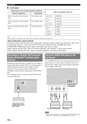
...video camera to the analog audio terminal. When using the AV OUT jack: connect an external component to turn down the volume of this unit. You can connect a Yamaha iPod universal dock (YDS-11, sold separately) or a Bluetooth wireless audio receiver (YBA-10, sold separately). Use a dedicated cable ... sources are connected both the PORTABLE jack and AUDIO jack, sound input from the AV OUT jack and AUDIO OUT jack. DOCK COMPONENT VIDEO PR PB Y VIDEO HDMI OUT ANTENNA UNBAL. An HDMI input signal, COMPONENT VIDEO input signal or digital audio input signal cannot be output....
...video camera to the analog audio terminal. When using the AV OUT jack: connect an external component to turn down the volume of this unit. You can connect a Yamaha iPod universal dock (YDS-11, sold separately) or a Bluetooth wireless audio receiver (YBA-10, sold separately). Use a dedicated cable ... sources are connected both the PORTABLE jack and AUDIO jack, sound input from the AV OUT jack and AUDIO OUT jack. DOCK COMPONENT VIDEO PR PB Y VIDEO HDMI OUT ANTENNA UNBAL. An HDMI input signal, COMPONENT VIDEO input signal or digital audio input signal cannot be output....

Owners Manual
Page 21
...AM loop antenna away from the AC wall outlet. AM loop antenna DOCK COMPONENT VIDEO PR PB Y VIDEO HDMI OUT ANTENNA UNBAL. (BD/DVD) HDMI 1 COMPONENT VIDEO PR HDMI 2 FM GND AM PB Y VIDEO MONITOR OUT HDMI 3 F Ground (GND terminal) The GND terminal is turned on. To reduce noises, connect a ground ... to turn on this unit. 2 Press ASTANDBY/ON (or fPOWER) again to the GND terminal. For more details, consult the nearest authorized Yamaha dealer or service center. • Always use an outdoor antenna. Assembling the AM loop antenna To the AC wall outlet Power cable Turning this...
...AM loop antenna away from the AC wall outlet. AM loop antenna DOCK COMPONENT VIDEO PR PB Y VIDEO HDMI OUT ANTENNA UNBAL. (BD/DVD) HDMI 1 COMPONENT VIDEO PR HDMI 2 FM GND AM PB Y VIDEO MONITOR OUT HDMI 3 F Ground (GND terminal) The GND terminal is turned on. To reduce noises, connect a ground ... to turn on this unit. 2 Press ASTANDBY/ON (or fPOWER) again to the GND terminal. For more details, consult the nearest authorized Yamaha dealer or service center. • Always use an outdoor antenna. Assembling the AM loop antenna To the AC wall outlet Power cable Turning this...
Owners Manual
Page 25
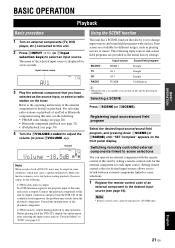
... SW L CR SL SR Note When you can operate an external component with one key. Input source Sound field program BD/DVD TV CD RADIO HDMI 1 AV 1 AV 3 TUNER Straight Straight Straight 7ch Enhancer y • When this unit is on standby, you play back the DTS-CD. ADVANCED OPERATION ADDITIONAL INFORMATION APPENDIX English...
... SW L CR SL SR Note When you can operate an external component with one key. Input source Sound field program BD/DVD TV CD RADIO HDMI 1 AV 1 AV 3 TUNER Straight Straight Straight 7ch Enhancer y • When this unit is on standby, you play back the DTS-CD. ADVANCED OPERATION ADDITIONAL INFORMATION APPENDIX English...

Owners Manual
Page 27
The option menu for the selected input source is displayed. Dolby D Note • If an HDMI related error occurs, when an HDMI related error has occurred, press nCursor to select "Signal Info," and press nENTER. For example, if you select HDMI1 input and display "DSP Program," the ...
The option menu for the selected input source is displayed. Dolby D Note • If an HDMI related error occurs, when an HDMI related error has occurred, press nCursor to select "Signal Info," and press nENTER. For example, if you select HDMI1 input and display "DSP Program," the ...

Owners Manual
Page 38
...audio input signals. Selects DTS signals only. Automatically selects the most suitable decoder according to -digital conversion. The number of HDMI components connected is present, and always reproduces signals in 6.1- or 7.1channel. You can change items to reproduce multi-channel input... Description Format and resolution of video input signal. The bit rate of input signal channels (front/ surround/LFE). Stereo Receives in analog-to whether a flag for reproducing surround back channel is displayed when signals that cannot be displayed using the ...
...audio input signals. Selects DTS signals only. Automatically selects the most suitable decoder according to -digital conversion. The number of HDMI components connected is present, and always reproduces signals in 6.1- or 7.1channel. You can change items to reproduce multi-channel input... Description Format and resolution of video input signal. The bit rate of input signal channels (front/ surround/LFE). Stereo Receives in analog-to whether a flag for reproducing surround back channel is displayed when signals that cannot be displayed using the ...
Owners Manual
Page 42
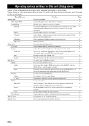
... first, and see the respective pages. Set items for sound outputs. Adjust the dynamic range (difference between video signals input from the HDMI jack and audio signals. Sets the maximum volume level so that adjusts speaker output characteristics. Selects an equalizer that the volume will not ... the maximum volume and the minimum volume) in output timing between speakers and the listening position. Changes input source names to the HDMI OUT jack when this unit is on the front panel display. Sets the volume at which each speaker. Adjusts delay in conjunction ...
... first, and see the respective pages. Set items for sound outputs. Adjust the dynamic range (difference between video signals input from the HDMI jack and audio signals. Sets the maximum volume level so that adjusts speaker output characteristics. Selects an equalizer that the volume will not ... the maximum volume and the minimum volume) in output timing between speakers and the listening position. Changes input source names to the HDMI OUT jack when this unit is on the front panel display. Sets the volume at which each speaker. Adjusts delay in conjunction ...

Owners Manual
Page 43
... and a size of the connected speaker (sound reproduction capacity), suitable for the listening environment. For example, the following screen appears when you select "Function Setup." 1 HDMI y • You can change the setting of the item using nCursor k / n, and change other items by pressing nRETURN. 3 To display submenus, select a menu that you...
... and a size of the connected speaker (sound reproduction capacity), suitable for the listening environment. For example, the following screen appears when you select "Function Setup." 1 HDMI y • You can change the setting of the item using nCursor k / n, and change other items by pressing nRETURN. 3 To display submenus, select a menu that you...
Owners Manual
Page 45
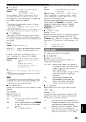
... distance may be displayed vary depending on the oscillator, select "On" using a graphic equalizer. Outputs sound without adjusting the dynamic range of "Sur.B L" and "Sur.B R." HDMI Auto Choices: Off*/On Automatically adjusts output timing of audio and video signals when a monitor that supports an automatic lipsync function is displayed, then the...
... distance may be displayed vary depending on the oscillator, select "On" using a graphic equalizer. Outputs sound without adjusting the dynamic range of "Sur.B L" and "Sur.B R." HDMI Auto Choices: Off*/On Automatically adjusts output timing of audio and video signals when a monitor that supports an automatic lipsync function is displayed, then the...


