
Service Manual
Page 26
... connect USB 2.0 devices. 16 Video connector VGA port to connect video monitor. 17 Compact Flash (CF) card Slot to remove (service action allowed). To operate these buttons unless instructed to help them locate the server in a crowded server room. Operational (no action required). 12 Serial management port SER MGT-Serial management port (serial connection to the CPU. Power is used for X-option cards. 7 Locate button/LED (white) Toggles on/off locally-Operators can turn...
... connect USB 2.0 devices. 16 Video connector VGA port to connect video monitor. 17 Compact Flash (CF) card Slot to remove (service action allowed). To operate these buttons unless instructed to help them locate the server in a crowded server room. Operational (no action required). 12 Serial management port SER MGT-Serial management port (serial connection to the CPU. Power is used for X-option cards. 7 Locate button/LED (white) Toggles on/off locally-Operators can turn...

Service Manual
Page 36
... Panel Controls and Indicators 1 23 4 56 7 1 Locate button/LED 2 Alert LED 3 Power/OK LED (system power) 4 Power button 2-2 Sun Fire X4500/X4540 Server Service Manual • May 2010 ■ Section 2.23, "Disabling OPROM Scanning" on page 2-86 2.1 Powering On the Server Before powering on your server for all fans, component heat sinks, air baffles, and the cover installed. Verify that power cords have been connected and that standby power is operated without...
... Panel Controls and Indicators 1 23 4 56 7 1 Locate button/LED 2 Alert LED 3 Power/OK LED (system power) 4 Power button 2-2 Sun Fire X4500/X4540 Server Service Manual • May 2010 ■ Section 2.23, "Disabling OPROM Scanning" on page 2-86 2.1 Powering On the Server Before powering on your server for all fans, component heat sinks, air baffles, and the cover installed. Verify that power cords have been connected and that standby power is operated without...

Service Manual
Page 42
.../PnP Menu Plug-and-Play (PnP) devices can be accessed from the Advanced menu. BIOS Security Settings Menu (X4500) Install or change the user and supervisor passwords. Enabling Chipkill improves system reliability but degrades system performance under specific applications. See Section t, "To Install a PCI-X or PCIe Card (FRU)" on page 2-12 for the locations of the seven top-level BIOS setup screens. Note that the Memory Chipkill...
.../PnP Menu Plug-and-Play (PnP) devices can be accessed from the Advanced menu. BIOS Security Settings Menu (X4500) Install or change the user and supervisor passwords. Enabling Chipkill improves system reliability but degrades system performance under specific applications. See Section t, "To Install a PCI-X or PCIe Card (FRU)" on page 2-12 for the locations of the seven top-level BIOS setup screens. Note that the Memory Chipkill...
Service Manual
Page 104
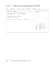
... Settings Menu (X4540) Main Advanced PCIPnP Boot Security Chipset Exit * Security Settings * Install or Change the * password. * * Supervisor Password :Not Installed * * * User Password :Not Installed * * * * * * Change Supervisor Password * * * Change User Password * * * * * * Boot Sector Virus Protection [Disabled] * * * * * * * * * * * * * * Select Screen * * * ** Select Item * * * Enter Change * * * F1 General Help * * * F10 Save and Exit * * * ESC Exit * * * * * * * 2-70 Sun Fire X4500/X4540 Server Service Manual...
... Settings Menu (X4540) Main Advanced PCIPnP Boot Security Chipset Exit * Security Settings * Install or Change the * password. * * Supervisor Password :Not Installed * * * User Password :Not Installed * * * * * * Change Supervisor Password * * * Change User Password * * * * * * Boot Sector Virus Protection [Disabled] * * * * * * * * * * * * * * Select Screen * * * ** Select Item * * * Enter Change * * * F1 General Help * * * F10 Save and Exit * * * ESC Exit * * * * * * * 2-70 Sun Fire X4500/X4540 Server Service Manual...

Service Manual
Page 117
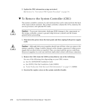
... press and release the recessed Power button on the front panel. It is to tell the system to a hard reset. See "Powering Off the Server" on page 3-70. 5. Remove the cable management assembly if necessary: ■ Sun Cable Management Assembly Installation Guide for hardware debugging only. 2.18 Using the Clear CMOS Jumper You can use this jumper to clear the server's CMOS settings in the case of incorrect...
... press and release the recessed Power button on the front panel. It is to tell the system to a hard reset. See "Powering Off the Server" on page 3-70. 5. Remove the cable management assembly if necessary: ■ Sun Cable Management Assembly Installation Guide for hardware debugging only. 2.18 Using the Clear CMOS Jumper You can use this jumper to clear the server's CMOS settings in the case of incorrect...
Service Manual
Page 119
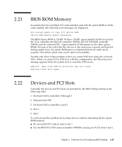
... problem for the other option ROMs. Because of this configuration, the following error messages are detected by the VGA controller, the Marvell controller (X4500), the LSI SAS1068E controller (X4540) and the on -board NICs. Chapter 2 Powering On and Configuring BIOS Settings 2-85 Approximately 42 KB remain for booting devices without exhausting all the option ROM memory: ■ Do not install PCI cards in the system are scanned...
... problem for the other option ROMs. Because of this configuration, the following error messages are detected by the VGA controller, the Marvell controller (X4500), the LSI SAS1068E controller (X4540) and the on -board NICs. Chapter 2 Powering On and Configuring BIOS Settings 2-85 Approximately 42 KB remain for booting devices without exhausting all the option ROM memory: ■ Do not install PCI cards in the system are scanned...

Service Manual
Page 138
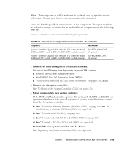
... an antistatic wrist strap to remove and replace the power distribution board (PDB), which is a FRU and should be replaced only by qualified service technicians. These part numbers are extremely sensitive to change over time. For an updated list of the following documents: ■ Sun Fire X4500/X4540 Server Installation Guide (820-4855) ■ Sun Fire X4540 Cable Management Arm Installation Guide (820-7349) (X4540 only) ■...
... an antistatic wrist strap to remove and replace the power distribution board (PDB), which is a FRU and should be replaced only by qualified service technicians. These part numbers are extremely sensitive to change over time. For an updated list of the following documents: ■ Sun Fire X4500/X4540 Server Installation Guide (820-4855) ■ Sun Fire X4540 Cable Management Arm Installation Guide (820-7349) (X4540 only) ■...
Service Manual
Page 148
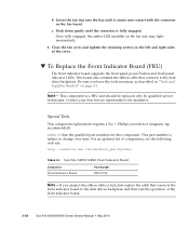
... the bay until the connector is bad, first replace the cable that connects to change over time. Lower the fan tray into contact with the connector on the left and right sides of the cover. ▼ To Replace the Front Indicator Board (FRU) The front indicator board supports the front panel power button and front panel indicator LEDs. b. TABLE 3-9 lists the qualified part numbers for assistance.
... the bay until the connector is bad, first replace the cable that connects to change over time. Lower the fan tray into contact with the connector on the left and right sides of the cover. ▼ To Replace the Front Indicator Board (FRU) The front indicator board supports the front panel power button and front panel indicator LEDs. b. TABLE 3-9 lists the qualified part numbers for assistance.
Service Manual
Page 160
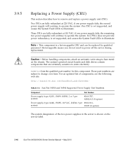
.../X4540 Server Service Manual • May 2010 Caution - Two PSUs does not provide power redundancy, is a hot-swappable CRU and can be replaced by qualified personnel. This component is not supported, and causes the System Fault LEDs to power off the server during replacement. Three PSUs are subject to remove and replace a power supply unit (PSU). TABLE 3-12 lists the qualified part number for this...
.../X4540 Server Service Manual • May 2010 Caution - Two PSUs does not provide power redundancy, is a hot-swappable CRU and can be replaced by qualified personnel. This component is not supported, and causes the System Fault LEDs to power off the server during replacement. Three PSUs are subject to remove and replace a power supply unit (PSU). TABLE 3-12 lists the qualified part number for this...
Service Manual
Page 164
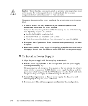
... service label. 1. If present, remove the cable management arm, or swivel open the cable management arm to the new power supply. See one of the way into the power supply bay. With the power supply handle in the server is connected to the power supply you want to keep the power cord secure. 4. Caution - To replace the cable management assembly if necessary. Align the power supply with the connector on the PDB. Use the power cord...
... service label. 1. If present, remove the cable management arm, or swivel open the cable management arm to the new power supply. See one of the way into the power supply bay. With the power supply handle in the server is connected to the power supply you want to keep the power cord secure. 4. Caution - To replace the cable management assembly if necessary. Align the power supply with the connector on the PDB. Use the power cord...
Service Manual
Page 170
... 3.3V standby power. TABLE 3-14 lists the qualified part numbers for up to X4540 Migration Guide. DIMM and CPU fault LEDs on the system controller indicates a problem with either the CPUs or the DIMMs. For the location of which component has a fault condition. To light the fault LEDs from the server. Contact your Sun Fire X4500 to change over time...
... 3.3V standby power. TABLE 3-14 lists the qualified part numbers for up to X4540 Migration Guide. DIMM and CPU fault LEDs on the system controller indicates a problem with either the CPUs or the DIMMs. For the location of which component has a fault condition. To light the fault LEDs from the server. Contact your Sun Fire X4500 to change over time...

Service Manual
Page 171
... be replaced. ■ The Battery fault LED: Off: The battery is powered up. Power off the server. Remove the cable management arm. See one of the following depending on your system: ■ Sun Fire X4500/X4540 Installation Guide ■ Sun X4500-J Slide Rail Installation Guide (X4500) ■ "Early-Production Slide Rail and CMA Information" on page 3-10. 2. The CPUs are located inside the system controller...
... be replaced. ■ The Battery fault LED: Off: The battery is powered up. Power off the server. Remove the cable management arm. See one of the following depending on your system: ■ Sun Fire X4500/X4540 Installation Guide ■ Sun X4500-J Slide Rail Installation Guide (X4500) ■ "Early-Production Slide Rail and CMA Information" on page 3-10. 2. The CPUs are located inside the system controller...
Service Manual
Page 179
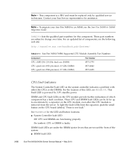
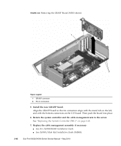
For an updated list of the following web site: http://sunsolve.sun.com/handbook_pub/Systems/ TABLE 3-15 Sun Fire X4500 Supported GRASP Board Part Numbers Component Part Number Graphics Service Processor (GRASP) board, includes SP board and #541-0597 video board 1. Remove the GRASP board: Note - Remove the cable management arm as described in one of components, see FIGURE 3-28). The GRASP board...
For an updated list of the following web site: http://sunsolve.sun.com/handbook_pub/Systems/ TABLE 3-15 Sun Fire X4500 Supported GRASP Board Part Numbers Component Part Number Graphics Service Processor (GRASP) board, includes SP board and #541-0597 video board 1. Remove the GRASP board: Note - Remove the cable management arm as described in one of components, see FIGURE 3-28). The GRASP board...
Service Manual
Page 180
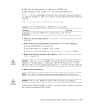
... on page 3-68. 7. Return the system controller and the cable management arm to the server. See "Replacing the System Controller (FRU)" on the I/O board. Then push the board into place. 6. Replace the cable management assembly if necessary: ■ Sun Fire X4500/X4540 Installation Guide ■ Sun X4500-J Slide Rail Installation Guide (X4500) 3-60 Sun Fire X4500/X4540 Server Service Manual • May 2010 FIGURE 3-28 Removing the...
... on page 3-68. 7. Return the system controller and the cable management arm to the server. See "Replacing the System Controller (FRU)" on the I/O board. Then push the board into place. 6. Replace the cable management assembly if necessary: ■ Sun Fire X4500/X4540 Installation Guide ■ Sun X4500-J Slide Rail Installation Guide (X4500) 3-60 Sun Fire X4500/X4540 Server Service Manual • May 2010 FIGURE 3-28 Removing the...
Service Manual
Page 184
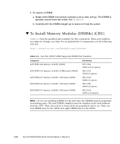
... (X-option) Note - These part numbers are installing DIMMs for the X4540. 3-64 Sun Fire X4500/X4540 Server Service Manual • May 2010 Rotate both DIMM slot ejectors outward as far as they will go. If you are subject to remove it from the socket. ▼ To Install Memory Modules (DIMMs) (CRU) TABLE 3-18 lists the qualified part numbers for this component...
... (X-option) Note - These part numbers are installing DIMMs for the X4540. 3-64 Sun Fire X4500/X4540 Server Service Manual • May 2010 Rotate both DIMM slot ejectors outward as far as they will go. If you are subject to remove it from the socket. ▼ To Install Memory Modules (DIMMs) (CRU) TABLE 3-18 lists the qualified part numbers for this component...
Service Manual
Page 186
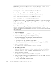
...; Sun Fire X4500/X4540 Installation Guide 3-66 Sun Fire X4500/X4540 Server Service Manual • May 2010 See "Replacing the System Controller (FRU)" on page 3-70. 4. This component is similar to installing the GRASP board. See "To Remove the System Controller (CRU)" on page 3-68. 6. To check if the driver of components. Option cards supported by qualified service technicians. For a list of supported PCI cards, see the following web...
...; Sun Fire X4500/X4540 Installation Guide 3-66 Sun Fire X4500/X4540 Server Service Manual • May 2010 See "Replacing the System Controller (FRU)" on page 3-70. 4. This component is similar to installing the GRASP board. See "To Remove the System Controller (CRU)" on page 3-68. 6. To check if the driver of components. Option cards supported by qualified service technicians. For a list of supported PCI cards, see the following web...
Service Manual
Page 188
... Remove a Power Supply (CRU)" on page 3-25. 6. Use an adhesive note or another method) so that you must return each drive to the new chassis. 11. Remove old chassis from their bays, you remove them from the drive bays. Reinstall all drives from the old system controller and install them on the replacement system controller. 3-68 Sun Fire X4500/X4540 Server Service Manual...
... Remove a Power Supply (CRU)" on page 3-25. 6. Use an adhesive note or another method) so that you must return each drive to the new chassis. 11. Remove old chassis from their bays, you remove them from the drive bays. Reinstall all drives from the old system controller and install them on the replacement system controller. 3-68 Sun Fire X4500/X4540 Server Service Manual...
Service Manual
Page 189
... "To Replace a CPU (FRU)" on page 3-64. This component is a FRU and must be moved to change over time. For an updated list of the following web site: http://sunsolve.sun.com/handbook_pub/Systems/ TABLE 3-20 Sun Fire X4540 Supported System Controller Part Numbers Component System Controller Upgrade Kit (includes I/O controller board (USB) and CPU board, 2x2356, 16x2GB (1GB), and document) System Controller Upgrade Kit (includes I/O controller board (USB) and...
... "To Replace a CPU (FRU)" on page 3-64. This component is a FRU and must be moved to change over time. For an updated list of the following web site: http://sunsolve.sun.com/handbook_pub/Systems/ TABLE 3-20 Sun Fire X4540 Supported System Controller Part Numbers Component System Controller Upgrade Kit (includes I/O controller board (USB) and CPU board, 2x2356, 16x2GB (1GB), and document) System Controller Upgrade Kit (includes I/O controller board (USB) and...
Service Manual
Page 190
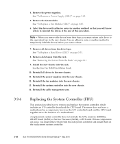
...-J Slide Rail Installation Guide (X4500) ■ "Early-Production Slide Rail and CMA Information" on the chassis connectors if either power supply did not shut down the power from the front panel and then unplug both power supplies should turn off then when you must pull the power cords from the power supplies to the components on the system controller handle. 3-70 Sun Fire X4500/X4540 Server Service Manual...
...-J Slide Rail Installation Guide (X4500) ■ "Early-Production Slide Rail and CMA Information" on the chassis connectors if either power supply did not shut down the power from the front panel and then unplug both power supplies should turn off then when you must pull the power cords from the power supplies to the components on the system controller handle. 3-70 Sun Fire X4500/X4540 Server Service Manual...
Service Manual
Page 208
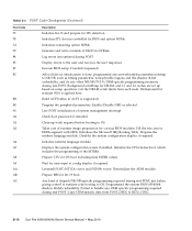
... kind of chipset (NB/SB)-specific programming required during end-POST. Copy OEM-specific data from each node. Initializes IPL devices controlled by BIOS and option ROMs. Initializes remaining option ROMs. Generate and write contents of the MTRRs. Log errors encountered during late-POST. Prepare CPU for DRAM, and L1 and L2 caches are set up work required before boot, which includes...
... kind of chipset (NB/SB)-specific programming required during end-POST. Copy OEM-specific data from each node. Initializes IPL devices controlled by BIOS and option ROMs. Initializes remaining option ROMs. Generate and write contents of the MTRRs. Log errors encountered during late-POST. Prepare CPU for DRAM, and L1 and L2 caches are set up work required before boot, which includes...
