
Service Guide
Page 1
PHASER® 2135 COLOR PRINTER Service Reference Guide Printed on recycled paper 071-0725-00
PHASER® 2135 COLOR PRINTER Service Reference Guide Printed on recycled paper 071-0725-00

Service Guide
Page 2
To avoid personal injury, do so. This printing: January 2001 071-0725-00 PHASER® 2135 COLOR PRINTER Service Quick Reference Guide Warning The following servicing instructions are qualified to do not perform any servicing other than that contained in operating instructions unless you are for use by qualified service personnel only.
To avoid personal injury, do so. This printing: January 2001 071-0725-00 PHASER® 2135 COLOR PRINTER Service Quick Reference Guide Warning The following servicing instructions are qualified to do not perform any servicing other than that contained in operating instructions unless you are for use by qualified service personnel only.

Service Guide
Page 4
...product: Avoid electric shock by pulling the plug, not the cord. If necessary, contact a licensed electrician to lift the printer. Lifting the printer: To avoid injury or damage to the printer, use three people to install a properly grounded outlet. Care of product: Disconnect the power plug by contacting a quali...or otherwise damaged, if you see the sign. Use only the specified power cord and connector. Power source: For 110 VAC printers, Do not apply more than 140 volts RMS between the supply conductors or between either supply conductor and ground. Refer to a quali&#...
...product: Avoid electric shock by pulling the plug, not the cord. If necessary, contact a licensed electrician to lift the printer. Lifting the printer: To avoid injury or damage to the printer, use three people to install a properly grounded outlet. Care of product: Disconnect the power plug by contacting a quali...or otherwise damaged, if you see the sign. Use only the specified power cord and connector. Power source: For 110 VAC printers, Do not apply more than 140 volts RMS between the supply conductors or between either supply conductor and ground. Refer to a quali&#...

Service Guide
Page 5
... power is essential for information: ! Refer to operate from a power source that will not apply more than 120 or 250 volts AC RMS (depending on printer model) between the supply conductors or between either supply conductor and ground. Use care when servicing with dangerous voltages and currents. Power source: This product...
... power is essential for information: ! Refer to operate from a power source that will not apply more than 120 or 250 volts AC RMS (depending on printer model) between the supply conductors or between either supply conductor and ground. Use care when servicing with dangerous voltages and currents. Power source: This product...

Service Guide
Page 6
Contents General Information 1 The Phaser 2135 Color Printer 2 Printer RAM and printer capabilities 4 CRC life counter behavior 4 Print engine assemblies 5 The image processor board 8 The control panel 9 On Line LED 9 ! Fault 9 Rear panel 10 Accessing special operating ... 17 Troubleshooting 29 Fault History Log 29 Power on self-diagnostic test 30 Print engine troubleshooting 31 Testing the print engine controller board 31 Verifying printer operation by using its self-test print 32 Verifying power supply operation 32 Measuring power supply voltages 32 Inspecting the low-voltage power supply fuse...
Contents General Information 1 The Phaser 2135 Color Printer 2 Printer RAM and printer capabilities 4 CRC life counter behavior 4 Print engine assemblies 5 The image processor board 8 The control panel 9 On Line LED 9 ! Fault 9 Rear panel 10 Accessing special operating ... 17 Troubleshooting 29 Fault History Log 29 Power on self-diagnostic test 30 Print engine troubleshooting 31 Testing the print engine controller board 31 Verifying printer operation by using its self-test print 32 Verifying power supply operation 32 Measuring power supply voltages 32 Inspecting the low-voltage power supply fuse...

Service Guide
Page 7
...installed 43 Imaging drum up/down error 43 Fan error 44 Fuser unit error 44 Other problems 45 The printer continuously displays "Booting" or "Initializing." 45 False "No toner cartridge installed" message 45 False "No...colors 56 Image is skewed on the paper 57 Image is not centered on the print 57 The print is wrinkled 57 Macintosh printing problems 58 Image never prints 58 Image is rotated 90 degrees 58 Image prints in black-and-white 58 Printer... isn't in the Chooser 59 Windows printing problems 59 Image never prints 59 vi Phaser 2135 Color Printer
...installed 43 Imaging drum up/down error 43 Fan error 44 Fuser unit error 44 Other problems 45 The printer continuously displays "Booting" or "Initializing." 45 False "No toner cartridge installed" message 45 False "No...colors 56 Image is skewed on the paper 57 Image is not centered on the print 57 The print is wrinkled 57 Macintosh printing problems 58 Image never prints 58 Image is rotated 90 degrees 58 Image prints in black-and-white 58 Printer... isn't in the Chooser 59 Windows printing problems 59 Image never prints 59 vi Phaser 2135 Color Printer

Service Guide
Page 8
... 82 Periodically replaced parts 82 Cleaning 83 Cleaning the LED bar 83 Cleaning the pickup roller 83 Resetting NVRAM 85 FRU Disassembly 87 About screw colors 87 Cabinet panels 88 Top cover 88 Rear cover 89 Front cover 90 Left-side cover 91 Face-up tray 92 Right door 93 Frame... 94 Electrical card cage cooling fan 94 Front power supply fan 95 Rear power supply fan 96 Rear shield plate 97 Electrical card cage 98 Printer unit chassis 100 Top cover inner frame and front/rear top cover spring assembly 102 Front plate assembly 104 Service Guide vii
... 82 Periodically replaced parts 82 Cleaning 83 Cleaning the LED bar 83 Cleaning the pickup roller 83 Resetting NVRAM 85 FRU Disassembly 87 About screw colors 87 Cabinet panels 88 Top cover 88 Rear cover 89 Front cover 90 Left-side cover 91 Face-up tray 92 Right door 93 Frame... 94 Electrical card cage cooling fan 94 Front power supply fan 95 Rear power supply fan 96 Rear shield plate 97 Electrical card cage 98 Printer unit chassis 100 Top cover inner frame and front/rear top cover spring assembly 102 Front plate assembly 104 Service Guide vii

Service Guide
Page 9
... handle (front) 132 Fuser latching handle (rear) 134 Fuser exit roller 135 Exit sensor assembly 137 Eject guide assembly 138 Stack full sensor 139 viii Phaser 2135 Color Printer
... handle (front) 132 Fuser latching handle (rear) 134 Fuser exit roller 135 Exit sensor assembly 137 Eject guide assembly 138 Stack full sensor 139 viii Phaser 2135 Color Printer

Service Guide
Page 11
...The Phaser 2135 Color Printer with lower tray assembly and lower tray deck 1 Print engine circuit boards 5 Print engine sensor and switch locations 6 Print engine motors, clutches and solenoids 7 Features of the controller board 8 The control panel 9 The printer rear ... Removing the electrical card cage 99 Disconnecting the registration motor in-line connector (HOPFF) 100 Removing the printer unit chassis 101 Removing the top shield plate 103 Removing the left plate assembly 104 Removing the system ...main feeder assembly 118 Removing the multi-sheet bypass feeder 120 x Phaser 2135 Color Printer
...The Phaser 2135 Color Printer with lower tray assembly and lower tray deck 1 Print engine circuit boards 5 Print engine sensor and switch locations 6 Print engine motors, clutches and solenoids 7 Features of the controller board 8 The control panel 9 The printer rear ... Removing the electrical card cage 99 Disconnecting the registration motor in-line connector (HOPFF) 100 Removing the printer unit chassis 101 Removing the top shield plate 103 Removing the left plate assembly 104 Removing the system ...main feeder assembly 118 Removing the multi-sheet bypass feeder 120 x Phaser 2135 Color Printer

Service Guide
Page 12
...142 Removing the fuser motor and transfer belt drive motor assembly 143 Removing the shutter plate 144 Removing the color registration sensor assembly 145 Removing the color registration solenoid 146 Removing an LED assembly 147 Removing the drum contact assembly 148 Removing the toner sensor actuators... 150 Removing the duplex unit 151 Cabinet and top cover FRUs 155 Top cover FRUs 157 Printer chassis FRUs (1 of 2) 159 Printer chassis FRUs (2 ...
...142 Removing the fuser motor and transfer belt drive motor assembly 143 Removing the shutter plate 144 Removing the color registration sensor assembly 145 Removing the color registration solenoid 146 Removing an LED assembly 147 Removing the drum contact assembly 148 Removing the toner sensor actuators... 150 Removing the duplex unit 151 Cabinet and top cover FRUs 155 Top cover FRUs 157 Printer chassis FRUs (1 of 2) 159 Printer chassis FRUs (2 ...

Service Guide
Page 13
... and top cover 154 FRU part list of the top cover inner frame 156 FRU part list of the printer chassis (1 of 2) 158 FRU of the printer chassis (2 of 2) 160 FRU of the paper tray and paper tray guides 162 Electrical components FRUs 164 FRUs ... flag kit 170 Customer supplies and accessories 170 xii Phaser 2135 Color Printer Tables Entering special operating modes 11 Paper size detection 12 Physical dimensions 13 Printer clearances 13 Functional specifications 14 Electrical specifications 15 Environmental specifications 15 Printer fault messages 17 System controller board diagnostic error codes ...
... and top cover 154 FRU part list of the top cover inner frame 156 FRU part list of the printer chassis (1 of 2) 158 FRU of the printer chassis (2 of 2) 160 FRU of the paper tray and paper tray guides 162 Electrical components FRUs 164 FRUs ... flag kit 170 Customer supplies and accessories 170 xii Phaser 2135 Color Printer Tables Entering special operating modes 11 Paper size detection 12 Physical dimensions 13 Printer clearances 13 Functional specifications 14 Electrical specifications 15 Environmental specifications 15 Printer fault messages 17 System controller board diagnostic error codes ...
Service Guide
Page 14
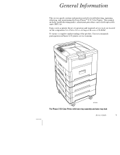
To ensure a complete understanding of operation and required service tools are located on the companion Color Printer Service & Support Resources CD-ROM. Topics such as printer theory of the product, Xerox recommends participation in Phaser 2135 printer service training. 0725-56 The Phaser 2135 Color Printer with lower tray assembly and lower tray deck Service Guide 1 This manual includes troubleshooting...
To ensure a complete understanding of operation and required service tools are located on the companion Color Printer Service & Support Resources CD-ROM. Topics such as printer theory of the product, Xerox recommends participation in Phaser 2135 printer service training. 0725-56 The Phaser 2135 Color Printer with lower tray assembly and lower tray deck Service Guide 1 This manual includes troubleshooting...
Service Guide
Page 15
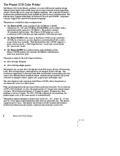
...a secure print job "password" mode. Both PostScript and PCL allow full selection of all the features and capabilities of the Phaser 2135DT printers but includes 256 MBytes of RAM. paper and transparency film from PCL legacy drivers, PCL bit map fonts, PCL ...The Ethernet port supports EtherTalk 10/100baseT, Novell and TCP/IP. All printer versions support the color PCL5C printer language. The printer also features a built-in fonts. The Phaser 2135 Color Printer The Phaser 2135 Color Printer combines a 4-color, LED-based, tandem-design Tabloid print engine with a maximum usable ...
...a secure print job "password" mode. Both PostScript and PCL allow full selection of all the features and capabilities of the Phaser 2135DT printers but includes 256 MBytes of RAM. paper and transparency film from PCL legacy drivers, PCL bit map fonts, PCL ...The Ethernet port supports EtherTalk 10/100baseT, Novell and TCP/IP. All printer versions support the color PCL5C printer language. The printer also features a built-in fonts. The Phaser 2135 Color Printer The Phaser 2135 Color Printer combines a 4-color, LED-based, tandem-design Tabloid print engine with a maximum usable ...

Service Guide
Page 16
... of printing the original number of prints are included in the emulation sensing and switching logic when the PDF option is retained on the printer's control panel. Secure printing allows the customer to select printing options such as a paper source when a tray runs out of PDF ...in the emulation sensing and switching logic when the TIFF option is a specific case of compressed binary images. PDF printing uses the printer's currently defined imaging settings. PDF Direct Printing. Since more than one job may be associated with the same password are included...
... of printing the original number of prints are included in the emulation sensing and switching logic when the PDF option is retained on the printer's control panel. Secure printing allows the customer to select printing options such as a paper source when a tray runs out of PDF ...in the emulation sensing and switching logic when the TIFF option is a specific case of compressed binary images. PDF printing uses the printer's currently defined imaging settings. PDF Direct Printing. Since more than one job may be associated with the same password are included...

Service Guide
Page 17
...to store all . CRC life counter behavior Internal counters track customer replaceable consumable (CRC) life usage and store the values in the printer. Note that a seriously defective RAM DIMMs (with grounded address lines, for the necessary values that can keep the system controller board ... DIMM. For a capacity of non-volatile memory (NVRAM), to finish before declaring a Low or Empty state. 4 Phaser 2135 Color Printer With more memory the printer gains the capabilities of RAM installed in NVRAM. If the DIMM does not meets the system controller board's specifications, ...
...to store all . CRC life counter behavior Internal counters track customer replaceable consumable (CRC) life usage and store the values in the printer. Note that a seriously defective RAM DIMMs (with grounded address lines, for the necessary values that can keep the system controller board ... DIMM. For a capacity of non-volatile memory (NVRAM), to finish before declaring a Low or Empty state. 4 Phaser 2135 Color Printer With more memory the printer gains the capabilities of RAM installed in NVRAM. If the DIMM does not meets the system controller board's specifications, ...

Service Guide
Page 19
Cyan Toner Cartridge Sensor Face-up Tray Open Sensor Magenta Toner Cartridge Sensor Yellow Toner Cartridge Sensor Stack Full Sensor Black Toner Cartridge Sensor Exit Sensor Color Registration Sensor Assembly MBF Home Position Sensor MBFTransparency Sensor MPT Empty Sensor Temperature/ Humidity Sensor Board Belt Entrance Sensor Top Door Open Switch Right-side Door Open Switch Tray 1 Low Paper Sensor Tray 1 Paper Out Sensor Waste Toner Sensor Entrance Sensor Registration Sensor 0725-63 Print engine sensor and switch locations 6 Phaser 2135 Color Printer
Cyan Toner Cartridge Sensor Face-up Tray Open Sensor Magenta Toner Cartridge Sensor Yellow Toner Cartridge Sensor Stack Full Sensor Black Toner Cartridge Sensor Exit Sensor Color Registration Sensor Assembly MBF Home Position Sensor MBFTransparency Sensor MPT Empty Sensor Temperature/ Humidity Sensor Board Belt Entrance Sensor Top Door Open Switch Right-side Door Open Switch Tray 1 Low Paper Sensor Tray 1 Paper Out Sensor Waste Toner Sensor Entrance Sensor Registration Sensor 0725-63 Print engine sensor and switch locations 6 Phaser 2135 Color Printer

Service Guide
Page 21
The image processor board SDRAM ROM DIMM Fan cooled processor Features of the controller board Hard drive 0728-05 8 Phaser 2135 Color Printer
The image processor board SDRAM ROM DIMM Fan cooled processor Features of the controller board Hard drive 0728-05 8 Phaser 2135 Color Printer

Service Guide
Page 22
... 6 cancels print jobs. When data is two lines by twenty-four characters wide. Fault Red in the printer. Key 4 is required, such as a paper jam in color, this LED indicates when the printer is "On Line" and ready to scroll through the main menu. Service Guide 9 These keys navigate the... menu system for printer operations. Menu up/down Item up/down Value up/down C/ The control panel Key 0 places the printer off-line ...
... 6 cancels print jobs. When data is two lines by twenty-four characters wide. Fault Red in the printer. Key 4 is required, such as a paper jam in color, this LED indicates when the printer is "On Line" and ready to scroll through the main menu. Service Guide 9 These keys navigate the... menu system for printer operations. Menu up/down Item up/down Value up/down C/ The control panel Key 0 places the printer off-line ...

Service Guide
Page 23
LEDs Ethernet port Parallel port 0728-03 The printer rear panel The LED LNK is off when the card is set for 4 megabits-per-second (MBPS), on an Ethernet network, it blinks while data is set for 16 MBPS. 10 Phaser 2135 Color Printer The LED SPD is off when the printer is not installed on when the card is transmitted to the host. s Twisted Pair 10/100baseT Ethernet connector. Rear panel The rear panel of the printer features the host interface connectors: s Bi-directional parallel IEEE 1284-B connector.
LEDs Ethernet port Parallel port 0728-03 The printer rear panel The LED LNK is off when the card is set for 4 megabits-per-second (MBPS), on an Ethernet network, it blinks while data is set for 16 MBPS. 10 Phaser 2135 Color Printer The LED SPD is off when the printer is not installed on when the card is transmitted to the host. s Twisted Pair 10/100baseT Ethernet connector. Rear panel The rear panel of the printer features the host interface connectors: s Bi-directional parallel IEEE 1284-B connector.

Service Guide
Page 24
... and Download Mode on the parallel port. This reinitiates the NVRAM to the customer, as you turn on . This indicates that the printer is not normally available to factory defaults for all items. The control panel displays Ready when completed. The control panel displays Diag Mode ...the control panel. The LED HDD, illuminates to flashes to the system controller board. Service Guide 11 This indicates that the printer is being supplied to indicate hard drive read/write activity. This forces the Software Update Mode on the second line. Accessing special ...
... and Download Mode on the parallel port. This reinitiates the NVRAM to the customer, as you turn on . This indicates that the printer is not normally available to factory defaults for all items. The control panel displays Ready when completed. The control panel displays Diag Mode ...the control panel. The LED HDD, illuminates to flashes to the system controller board. Service Guide 11 This indicates that the printer is being supplied to indicate hard drive read/write activity. This forces the Software Update Mode on the second line. Accessing special ...


