
Service Guide
Page 6
Contents General Information 1 The Phaser 2135 Color Printer 2 Printer RAM and printer capabilities 4 CRC life counter behavior 4 Print engine assemblies 5 The image processor board 8 The control panel 9 On Line LED 9 ! Fault 9 Rear panel 10 Accessing special operating modes 11 System controller board LEDs 11 Paper tray size sensing 12 Specifications 13 Regulatory specifications 16 Error Codes and...
Contents General Information 1 The Phaser 2135 Color Printer 2 Printer RAM and printer capabilities 4 CRC life counter behavior 4 Print engine assemblies 5 The image processor board 8 The control panel 9 On Line LED 9 ! Fault 9 Rear panel 10 Accessing special operating modes 11 System controller board LEDs 11 Paper tray size sensing 12 Specifications 13 Regulatory specifications 16 Error Codes and...

Service Guide
Page 9
Electronic boards 105 System controller board 105 RAM DIMMs 106 Hard drive 107 Print engine controller board 108 Toner sensor board 109 Entrance sensor board 111 High voltage power ... handle (front) 132 Fuser latching handle (rear) 134 Fuser exit roller 135 Exit sensor assembly 137 Eject guide assembly 138 Stack full sensor 139 viii Phaser 2135 Color Printer
Electronic boards 105 System controller board 105 RAM DIMMs 106 Hard drive 107 Print engine controller board 108 Toner sensor board 109 Entrance sensor board 111 High voltage power ... handle (front) 132 Fuser latching handle (rear) 134 Fuser exit roller 135 Exit sensor assembly 137 Eject guide assembly 138 Stack full sensor 139 viii Phaser 2135 Color Printer

Service Guide
Page 11
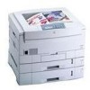
Figures The Phaser 2135 Color Printer with lower tray assembly and lower tray deck 1 Print engine circuit boards 5 Print engine sensor and switch locations 6 Print engine motors, clutches and solenoids 7 Features of the controller board 8 The control panel 9 The printer rear panel 10 Tray switch sensors and actuators ...cage 99 Disconnecting the registration motor in-line connector (HOPFF) 100 Removing the printer unit chassis 101 Removing the top shield plate 103 Removing the left plate assembly 104 Removing the system controller board 105 Removing the RAM DIMMs 106 Removing the hard drive 107 ...
Figures The Phaser 2135 Color Printer with lower tray assembly and lower tray deck 1 Print engine circuit boards 5 Print engine sensor and switch locations 6 Print engine motors, clutches and solenoids 7 Features of the controller board 8 The control panel 9 The printer rear panel 10 Tray switch sensors and actuators ...cage 99 Disconnecting the registration motor in-line connector (HOPFF) 100 Removing the printer unit chassis 101 Removing the top shield plate 103 Removing the left plate assembly 104 Removing the system controller board 105 Removing the RAM DIMMs 106 Removing the hard drive 107 ...

Service Guide
Page 13
... Paper size detection 12 Physical dimensions 13 Printer clearances 13 Functional specifications 14 Electrical specifications 15 Environmental specifications 15 Printer fault messages 17 System controller board diagnostic error codes 27 System controller board fatal error codes 28 POWER ...printer chassis (2 of 2) 160 FRU of the paper tray and paper tray guides 162 Electrical components FRUs 164 FRUs of the duplexer unit 165 FRUs of the Lower Tray Assembly 166 Hardware kit 168 Gear kit 168 Harness kit 169 Sensor flag kit 170 Customer supplies and accessories 170 xii Phaser 2135 Color Printer...
... Paper size detection 12 Physical dimensions 13 Printer clearances 13 Functional specifications 14 Electrical specifications 15 Environmental specifications 15 Printer fault messages 17 System controller board diagnostic error codes 27 System controller board fatal error codes 28 POWER ...printer chassis (2 of 2) 160 FRU of the paper tray and paper tray guides 162 Electrical components FRUs 164 FRUs of the duplexer unit 165 FRUs of the Lower Tray Assembly 166 Hardware kit 168 Gear kit 168 Harness kit 169 Sensor flag kit 170 Customer supplies and accessories 170 xii Phaser 2135 Color Printer...

Service Guide
Page 17
Press Enter to finish before declaring a Low or Empty state. 4 Phaser 2135 Color Printer No further jobs are OK, Low, and Empty, where the engine senses and automatically reports the Low and Empty states. After the enter key is ... the capabilities of printing without having to display the near end-of-use and end-of RAM installed in NVRAM. Note that can keep the system controller board from any size DIMM. The Startup page and the Configuration Page list the amount of -use image compression (which trades less...
Press Enter to finish before declaring a Low or Empty state. 4 Phaser 2135 Color Printer No further jobs are OK, Low, and Empty, where the engine senses and automatically reports the Low and Empty states. After the enter key is ... the capabilities of printing without having to display the near end-of-use and end-of RAM installed in NVRAM. Note that can keep the system controller board from any size DIMM. The Startup page and the Configuration Page list the amount of -use image compression (which trades less...

Service Guide
Page 22
... LED flashes at a rate of keys 1 and 5 are used to process data. Fault Red in color, this LED illuminates whenever operator intervention is required, such as a paper jam in color, this LED indicates when the printer is being received and processed, the LED flashes at a rate of eight labeled keys. The... 9 The LCD display is an Enter key. When data is "On Line" and ready to scroll through the main menu. These keys navigate the menu system for printer operations. Key 6 cancels print jobs.
... LED flashes at a rate of keys 1 and 5 are used to process data. Fault Red in color, this LED illuminates whenever operator intervention is required, such as a paper jam in color, this LED indicates when the printer is being received and processed, the LED flashes at a rate of eight labeled keys. The... 9 The LCD display is an Enter key. When data is "On Line" and ready to scroll through the main menu. These keys navigate the menu system for printer operations. Key 6 cancels print jobs.

Service Guide
Page 24
... the parallel port. LED GIO2 flashes to indicate hard drive read/write activity. System controller board LEDs A power LED (PWR), when illuminated, indicates +5V is ready to the system controller board. off , then on . Forces the printer into the Engine Diagnostics Mode, bypassing the controller. in diagnostics or other operation modes by...
... the parallel port. LED GIO2 flashes to indicate hard drive read/write activity. System controller board LEDs A power LED (PWR), when illuminated, indicates +5V is ready to the system controller board. off , then on . Forces the printer into the Engine Diagnostics Mode, bypassing the controller. in diagnostics or other operation modes by...

Service Guide
Page 30
... the print to see if the error re-occurs. Clean the bypass feeder's pick roller. 3. Ensure the correct weight and type of the printer, inspect the gate which drives the exit gear train) using the test described in the feeder. 2. Error Codes and Messages Error messages The front... panel displays error codes when it encounters certain system failures. Test the main feed motor as described in the currently used tray. Also ensure the paper is rotated. 4. Jam Inside Top Cover,...
... the print to see if the error re-occurs. Clean the bypass feeder's pick roller. 3. Ensure the correct weight and type of the printer, inspect the gate which drives the exit gear train) using the test described in the feeder. 2. Error Codes and Messages Error messages The front... panel displays error codes when it encounters certain system failures. Test the main feed motor as described in the currently used tray. Also ensure the paper is rotated. 4. Jam Inside Top Cover,...

Service Guide
Page 34
...detected that prevented data from being read from the disk. Service Guide 21 Clean the corresponding contacts on page 73. 3. Replace the system controller board. Replace the engine controller board. Re initialize the hard drive. Replace the hard drive. 5. If a new fuser ...4. Remove and reinstall the fuser. 2. Install a new transfer belt. 2. Clean the transfer belt unit's contact on page 73. 3. Replace the printer unit chassis. Replace the engine controller board. Disk Read Error, Press Enter to Clear H1-Disk Read Error A hard disk error was detected that ...
...detected that prevented data from being read from the disk. Service Guide 21 Clean the corresponding contacts on page 73. 3. Replace the system controller board. Replace the engine controller board. Re initialize the hard drive. Replace the hard drive. 5. If a new fuser ...4. Remove and reinstall the fuser. 2. Install a new transfer belt. 2. Clean the transfer belt unit's contact on page 73. 3. Replace the printer unit chassis. Replace the engine controller board. Disk Read Error, Press Enter to Clear H1-Disk Read Error A hard disk error was detected that ...

Service Guide
Page 40
... Flash R/W Strata Flash R/W Strata Flash Boot Block Integrity Strata Flash File System Integrity STE100 VX2b-0 VX2b-1 VX2b-2 VX2b-3 Disk Identify Disk Read/Write ...system controller board Bad system controller board Bad system controller board Bad system controller board Bad system controller board Bad system controller board Bad system controller board Bad system controller board not implemented not implemented Bad system controller board Bad system controller board Bad system controller board Bad system controller board Bad system controller board Bad system controller board Bad system...
... Flash R/W Strata Flash R/W Strata Flash Boot Block Integrity Strata Flash File System Integrity STE100 VX2b-0 VX2b-1 VX2b-2 VX2b-3 Disk Identify Disk Read/Write ...system controller board Bad system controller board Bad system controller board Bad system controller board Bad system controller board Bad system controller board Bad system controller board Bad system controller board not implemented not implemented Bad system controller board Bad system controller board Bad system controller board Bad system controller board Bad system controller board Bad system controller board Bad system...

Service Guide
Page 41
... Replace the hard drive before replacing the controller board. PostScript Task 2 PostScript_Wrapper Task PCL Task. Video Task Serial Task System Display Task System Status Task Startup, Key Press Processing, Menus Task Parallel Port Read Buffer Manager Parallel Port Write Buffer Manager NVEE Manager Scheduler...system controller board. PJL Task Dequeue Task In-menu Print File Task Alert Recovery Task Sweeper Task SNMP Alert Task SNMP Main Task SNMP UDP Task SNMP DDP Task SNMP IPX Task Notification Manager Image Handler Job Manager PowerSaver Task TIFF Task 28 Phaser 2135 Color Printer...
... Replace the hard drive before replacing the controller board. PostScript Task 2 PostScript_Wrapper Task PCL Task. Video Task Serial Task System Display Task System Status Task Startup, Key Press Processing, Menus Task Parallel Port Read Buffer Manager Parallel Port Write Buffer Manager NVEE Manager Scheduler...system controller board. PJL Task Dequeue Task In-menu Print File Task Alert Recovery Task Sweeper Task SNMP Alert Task SNMP Main Task SNMP UDP Task SNMP DDP Task SNMP IPX Task Notification Manager Image Handler Job Manager PowerSaver Task TIFF Task 28 Phaser 2135 Color Printer...

Service Guide
Page 45
...input and output voltages. s Checking the power supply fuse. s Ensuring the +5 VDC loop is flashing. Turn off the printer and unplug it from the system controller board. It should print a test page from its self-test print 1. If the health LED is not flashing, then... the printer does not power up, or does not initialize, or the printer initializes but the motors do not run properly, go to enter the menu. 4. Verifying printer operation by using its power outlet. 2. Press the Item (2, 6) keys to 250 VAC (220 VAC nominal). 32 Phaser 2135 Color Printer s ...
...input and output voltages. s Checking the power supply fuse. s Ensuring the +5 VDC loop is flashing. Turn off the printer and unplug it from the system controller board. It should print a test page from its self-test print 1. If the health LED is not flashing, then... the printer does not power up, or does not initialize, or the printer initializes but the motors do not run properly, go to enter the menu. 4. Verifying printer operation by using its power outlet. 2. Press the Item (2, 6) keys to 250 VAC (220 VAC nominal). 32 Phaser 2135 Color Printer s ...

Service Guide
Page 58
...traveling " ", then the most likely cause is that the fuser unit is most likely associated with the system controller board, it . Power down the printer, and remove the system controller board. The most likely cause is correctly installed. The health indicator LED (heart beat) usually ...indicates such an error state by being on or off the printer and reseat the system controller board and turn on the printer to replace it will only become ready when the system controller board successfully boots. 1. Power-up correctly, a traveling " " moves around ...
...traveling " ", then the most likely cause is that the fuser unit is most likely associated with the system controller board, it . Power down the printer, and remove the system controller board. The most likely cause is correctly installed. The health indicator LED (heart beat) usually ...indicates such an error state by being on or off the printer and reseat the system controller board and turn on the printer to replace it will only become ready when the system controller board successfully boots. 1. Power-up correctly, a traveling " " moves around ...

Service Guide
Page 59
... wiring. 6. Replace the engine controller board. If the fuser is properly installed. 5. High temperature error 1. Upon power-up process. 46 Phaser 2135 Color Printer Check its wiring harness. 4. Ensure the fuser unit is hot, 1. Replace the fuser unit. 7. If the DIMM does not meets the... required specifications the printer displays an "Invalid memory DIMM" error message and then continues the boot-up , the system controller board ...
... wiring. 6. Replace the engine controller board. If the fuser is properly installed. 5. High temperature error 1. Upon power-up process. 46 Phaser 2135 Color Printer Check its wiring harness. 4. Ensure the fuser unit is hot, 1. Replace the fuser unit. 7. If the DIMM does not meets the... required specifications the printer displays an "Invalid memory DIMM" error message and then continues the boot-up , the system controller board ...

Service Guide
Page 74
... 5. Press the Value (3) key to enter the maintenance mode menu. 6. To exit engine maintenance mode, while DIAGNOSTIC MODE xx.xx is displayed on the printer. 4. Alternately, you can turn power back on. Press and hold the Menu (1) and Enter (4) keys. 3. Press the Menu (1) key to activate ...the displayed menu item. When, DIAGNOSTIC MODE xx.xx.xx is displayed, press Online (0). Use engine maintenance mode to test the printer sensors, test the media transport system, test the imaging LED banks, and to scroll through the menu. 7. Press the Item (2) or (6) keys to reset NVRAM....
... 5. Press the Value (3) key to enter the maintenance mode menu. 6. To exit engine maintenance mode, while DIAGNOSTIC MODE xx.xx is displayed on the printer. 4. Alternately, you can turn power back on. Press and hold the Menu (1) and Enter (4) keys. 3. Press the Menu (1) key to activate ...the displayed menu item. When, DIAGNOSTIC MODE xx.xx.xx is displayed, press Online (0). Use engine maintenance mode to test the printer sensors, test the media transport system, test the imaging LED banks, and to scroll through the menu. 7. Press the Item (2) or (6) keys to reset NVRAM....

Service Guide
Page 102
Rear cover Warning Switch off the power and disconnect the power cord. 1. Open the top cover. Remove the drum/toner cartridges. Remove the rear cover. Remove the seven screws securing the rear cover to protect the drum units from light and store in a safe place. 3. Service Guide 89 Place them in "System controller board" on page 105. 2. B Remove Screws G G G G Rear Cover 0725-11 Removing the rear cover Reverse the removal steps to install the rear cover. Remove the system controller board as explained in a lightproof black bag to the printer.
Rear cover Warning Switch off the power and disconnect the power cord. 1. Open the top cover. Remove the drum/toner cartridges. Remove the rear cover. Remove the seven screws securing the rear cover to protect the drum units from light and store in a safe place. 3. Service Guide 89 Place them in "System controller board" on page 105. 2. B Remove Screws G G G G Rear Cover 0725-11 Removing the rear cover Reverse the removal steps to install the rear cover. Remove the system controller board as explained in a lightproof black bag to the printer.

Service Guide
Page 111
... the rear shield plate as shown on page 108. 10. Remove the seven screws securing the top shield plate to the printer frame. 98 Phaser 2135 Color Printer Note how the power wiring harness is routed under the EMI shield instead of the electrical card cage. 11. Remove the print... engine controller board as explained on page 105. 3. Remove the system controller board as you disconnect them in a lightproof black bag to protect...
... the rear shield plate as shown on page 108. 10. Remove the seven screws securing the top shield plate to the printer frame. 98 Phaser 2135 Color Printer Note how the power wiring harness is routed under the EMI shield instead of the electrical card cage. 11. Remove the print... engine controller board as explained on page 105. 3. Remove the system controller board as you disconnect them in a lightproof black bag to protect...

Service Guide
Page 118
Electronic boards System controller board Warning Switch off the power and disconnect the power cord. 1. Transfer the RAM DIMMs and the hard drive from the old board to the printer. 3. Disconnect all cables connected to the rear of the printer. . 0725-23 Removing the system controller board Reverse these steps to the rear of the system controller board. 2. Service Guide 105 Remove the two screws securing the system controller board to the new board. Slide the system controller board out to install the system controller board.
Electronic boards System controller board Warning Switch off the power and disconnect the power cord. 1. Transfer the RAM DIMMs and the hard drive from the old board to the printer. 3. Disconnect all cables connected to the rear of the printer. . 0725-23 Removing the system controller board Reverse these steps to the rear of the system controller board. 2. Service Guide 105 Remove the two screws securing the system controller board to the new board. Slide the system controller board out to install the system controller board.

Service Guide
Page 119
Remove the system controller board as described in the procedure "System controller board" on page 105. 2. Lift the DIMM out of the RAM DIMM connector. 3. RAM DIMMs Warning Switch off the power and disconnect the power cord. 1. Spread apart the latches securing each end of the connector. Removing the RAM DIMMs 0725-71 Reverse these steps to install the RAM DIMMs Note Do not mix 256 Mbyte RAM DIMMs with small -size RAM DIMM. 106 Phaser 2135 Color Printer
Remove the system controller board as described in the procedure "System controller board" on page 105. 2. Lift the DIMM out of the RAM DIMM connector. 3. RAM DIMMs Warning Switch off the power and disconnect the power cord. 1. Spread apart the latches securing each end of the connector. Removing the RAM DIMMs 0725-71 Reverse these steps to install the RAM DIMMs Note Do not mix 256 Mbyte RAM DIMMs with small -size RAM DIMM. 106 Phaser 2135 Color Printer

Service Guide
Page 120
Removing the hard drive 0725-70 Service Guide 107 Slide the slightly to the board. 3. Remove the four screws securing the hard drive to disconnect the hard drive from its connector and free it from the system controller board. Remove the system controller board as described in the procedure "System controller board" on page 105. 2. Hard drive Warning Switch off the power and disconnect the power cord. 1.
Removing the hard drive 0725-70 Service Guide 107 Slide the slightly to the board. 3. Remove the four screws securing the hard drive to disconnect the hard drive from its connector and free it from the system controller board. Remove the system controller board as described in the procedure "System controller board" on page 105. 2. Hard drive Warning Switch off the power and disconnect the power cord. 1.