Dimension Guide
Page 1
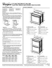
...CM) AND 30" (76.2 CM) ELECTRIC SINGLE AND DOUBLE BUILT-IN OVEN PRODUCT MODEL SERIES PRODUCT DIMENSIONS WOD51EC0A WOD51EC7A WOD93EC0A WOD93EC7A WOS51EC0A WOS51EC7A WOS92EC0A WOS92EC7A Electrical: To properly install your oven, you must determine the type of electrical connection you will be connected ... W 2820 W 5580 W 5610 W 240 VAC 15.4 A 15.5 A 30.7 A 30.8 A 208 VAC 13.4 A 13.6 A 26.8 A 27.0 A Because Whirlpool Corporation policy includes a continuous commitment to improve our products, we reserve the right to the proper electrical voltage and frequency as specified on double...
...CM) AND 30" (76.2 CM) ELECTRIC SINGLE AND DOUBLE BUILT-IN OVEN PRODUCT MODEL SERIES PRODUCT DIMENSIONS WOD51EC0A WOD51EC7A WOD93EC0A WOD93EC7A WOS51EC0A WOS51EC7A WOS92EC0A WOS92EC7A Electrical: To properly install your oven, you must determine the type of electrical connection you will be connected ... W 2820 W 5580 W 5610 W 240 VAC 15.4 A 15.5 A 30.7 A 30.8 A 208 VAC 13.4 A 13.6 A 26.8 A 27.0 A Because Whirlpool Corporation policy includes a continuous commitment to improve our products, we reserve the right to the proper electrical voltage and frequency as specified on double...
Dimension Guide
Page 2
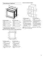
...)* recommended cutout height G. 24" (60.7 cm) cutout depth 30" (76.2 cm) models A. 30" (76.2 cm) min. Because Whirlpool Corporation policy includes a continuous commitment to top of cutout to improve Dimensions are for planning purposes only. bottom of cabinet door F. 28" (71... to floor D. 28¹⁄₂" (72.4 cm) cutout width E. 1¹⁄₂" (3.8 cm) min. Page 2 of cutout to change without cooktop installed above) A B Single Ovens Installed in Cabinet A B D F G E C B D F G E C 27" (68.6 cm) models A. 27" (68.6 cm) min. bottom of cabinet door F. 28"...
...)* recommended cutout height G. 24" (60.7 cm) cutout depth 30" (76.2 cm) models A. 30" (76.2 cm) min. Because Whirlpool Corporation policy includes a continuous commitment to top of cutout to improve Dimensions are for planning purposes only. bottom of cabinet door F. 28" (71... to floor D. 28¹⁄₂" (72.4 cm) cutout width E. 1¹⁄₂" (3.8 cm) min. Page 2 of cutout to change without cooktop installed above) A B Single Ovens Installed in Cabinet A B D F G E C B D F G E C 27" (68.6 cm) models A. 27" (68.6 cm) min. bottom of cabinet door F. 28"...
Installation Guide
Page 1
... ENCASTR 17 INSTALLATION REQUIREMENTS 2 Tools and Parts 2 Location Requirements 2 Electrical Requirements 5 INSTALLATION INSTRUCTIONS 6 Prepare Built-In Oven 6 Remove Oven Door 6 Positioning Oven Feet for local electrical inspector's use. WARNING You can be killed or seriously injured if you and others are not... manual and on your appliance. IMPORTANT: Save for Multiple Cabinet Cutout Heights .......7 Make Electrical Connection 10 Install Oven 12 Complete Installation 14 EXIGENCES D'INSTALLATION 17 Outillage et pièces 17 Exigences d'emplacement 18 Spé...
... ENCASTR 17 INSTALLATION REQUIREMENTS 2 Tools and Parts 2 Location Requirements 2 Electrical Requirements 5 INSTALLATION INSTRUCTIONS 6 Prepare Built-In Oven 6 Remove Oven Door 6 Positioning Oven Feet for local electrical inspector's use. WARNING You can be killed or seriously injured if you and others are not... manual and on your appliance. IMPORTANT: Save for Multiple Cabinet Cutout Heights .......7 Make Electrical Connection 10 Install Oven 12 Complete Installation 14 EXIGENCES D'INSTALLATION 17 Outillage et pièces 17 Exigences d'emplacement 18 Spé...
Installation Guide
Page 2
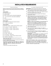
...models KEBK171B, KEBK101B, KEBK276B, KEBK206B, KEBS179B, KEBS109B, KEBS277B, KEBS279B, KEBS207B, KEBS209B, KEBU109B and KEBU209B. **Foam strip not included with double oven. Tools needed ■ Phillips screwdriver ■ Measuring tape ■ Hand or electric drill (for wall cabinet installations) ■ 1" (2.5 cm... installation, it is required. INSTALLATION REQUIREMENTS Tools and Parts Gather the required tools and parts before starting installation. double oven ■ Four grommets - IMPORTANT: To avoid damage to your builder or cabinet supplier to the junction box. It...
...models KEBK171B, KEBK101B, KEBK276B, KEBK206B, KEBS179B, KEBS109B, KEBS277B, KEBS279B, KEBS207B, KEBS209B, KEBU109B and KEBU209B. **Foam strip not included with double oven. Tools needed ■ Phillips screwdriver ■ Measuring tape ■ Hand or electric drill (for wall cabinet installations) ■ 1" (2.5 cm... installation, it is required. INSTALLATION REQUIREMENTS Tools and Parts Gather the required tools and parts before starting installation. double oven ■ Four grommets - IMPORTANT: To avoid damage to your builder or cabinet supplier to the junction box. It...
Installation Guide
Page 3
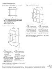
... in Cabinet A B D C F A G E D E 27" (68.6 cm) models A. 28¾" (72.8 cm) max. Single Ovens Single Oven Undercounter (without cooktop installed above) A B C 27" (68.6 cm) models A. 27" (68.6 cm) min. cabinet width B. 1" (2.5 cm) top of cutout to floor D. 25¹⁄₂"... cm)* recommended cutout height G. 24" (60.7 cm) cutout depth NOTE: The cutout height can be between 26 68.4 cm) and 29 74.8 cm) for single ovens. top of cutout to underside of countertop C. 5¹⁄₄" (13.3 cm) bottom of cutout to floor D. 25¹⁄₂" (64.8 cm) cutout ...
... in Cabinet A B D C F A G E D E 27" (68.6 cm) models A. 28¾" (72.8 cm) max. Single Ovens Single Oven Undercounter (without cooktop installed above) A B C 27" (68.6 cm) models A. 27" (68.6 cm) min. cabinet width B. 1" (2.5 cm) top of cutout to floor D. 25¹⁄₂"... cm)* recommended cutout height G. 24" (60.7 cm) cutout depth NOTE: The cutout height can be between 26 68.4 cm) and 29 74.8 cm) for single ovens. top of cutout to underside of countertop C. 5¹⁄₄" (13.3 cm) bottom of cutout to floor D. 25¹⁄₂" (64.8 cm) cutout ...
Installation Guide
Page 4
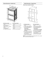
... height G. 24" (60.7 cm) cutout depth NOTE: The cutout height can be between 48⁷⁄₈" (124.1 cm) and 52 132.6 cm) for double ovens. 4 bottom of cutout to top of cabinet door F. 50¹⁄₄" (127.6 cm)* recommended cutout height G. 24" (60.7 cm) cutout depth 30" (76.2 cm... 124.0 cm) recessed height D. 23¹⁄₄" (59.1 cm) max. D. 25¹⁄₂" (64.8 cm) cutout width E. 1¹⁄₂" (3.8 cm) min. Double Ovens Double Ovens Installed in Cabinet A A C B D F E D 27" (68.6 cm) models A. 51 130.0 cm) max. Double...
... height G. 24" (60.7 cm) cutout depth NOTE: The cutout height can be between 48⁷⁄₈" (124.1 cm) and 52 132.6 cm) for double ovens. 4 bottom of cutout to top of cabinet door F. 50¹⁄₄" (127.6 cm)* recommended cutout height G. 24" (60.7 cm) cutout depth 30" (76.2 cm... 124.0 cm) recessed height D. 23¹⁄₄" (59.1 cm) max. D. 25¹⁄₂" (64.8 cm) cutout width E. 1¹⁄₂" (3.8 cm) min. Double Ovens Double Ovens Installed in Cabinet A A C B D F E D 27" (68.6 cm) models A. 51 130.0 cm) max. Double...
Installation Guide
Page 5
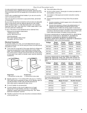
.... A copy of solid copper wire to the proper electrical voltage and frequency as specified on double ovens. For power requirements for models WOS51EC7A, WOS51EC0A, WOD51EC7A, WOD51EC0A, WOS92EC7A, WOS92EC0A, WOD93EC7A, WOD93EC0A, MEW7527A, MEW7530A, MEW7627A, MEW7630A, MEW9537A, MEW9627A, MEW9530A and MEW9630A, ...aluminum wiring to aluminum. Voltage 240 VAC Single Thermal 3690 W Single Convect 3720 W Double Thermal 7370 W Double Convect 7400 W ■ Oven must be connected directly to the junction box. 208 VAC 14.9 A 15.0 A 29.8 A 29.9 A For power requirements for models...
.... A copy of solid copper wire to the proper electrical voltage and frequency as specified on double ovens. For power requirements for models WOS51EC7A, WOS51EC0A, WOD51EC7A, WOD51EC0A, WOS92EC7A, WOS92EC0A, WOD93EC7A, WOD93EC0A, MEW7527A, MEW7530A, MEW7627A, MEW7630A, MEW9537A, MEW9627A, MEW9530A and MEW9630A, ...aluminum wiring to aluminum. Voltage 240 VAC Single Thermal 3690 W Single Convect 3720 W Double Thermal 7370 W Double Convect 7400 W ■ Oven must be connected directly to the junction box. 208 VAC 14.9 A 15.0 A 29.8 A 29.9 A For power requirements for models...
Installation Guide
Page 6
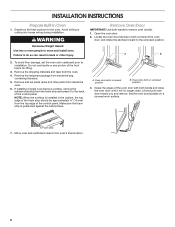
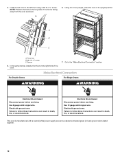
... When the cooktop is positioned against the cabinet face. Set the oven door(s) aside on the final location for lifting. 3. Remove the hardware package from the oven. 4. Remove and set the oven onto cardboard prior to installation. A. WARNING Excessive Weight Hazard Use ... INSTRUCTIONS Prepare Built-In Oven 1. Open the oven door. 2. Oven door latch in the cabinet, the top edge of the oven door with both hands to the oven's final location. 6 Move oven and cardboard close . Remove the shipping materials and tape from inside the oven. 6. Oven door latch in back ...
... When the cooktop is positioned against the cabinet face. Set the oven door(s) aside on the final location for lifting. 3. Remove the hardware package from the oven. 4. Remove and set the oven onto cardboard prior to installation. A. WARNING Excessive Weight Hazard Use ... INSTRUCTIONS Prepare Built-In Oven 1. Open the oven door. 2. Oven door latch in the cabinet, the top edge of the oven door with both hands to the oven's final location. 6 Move oven and cardboard close . Remove the shipping materials and tape from inside the oven. 6. Oven door latch in back ...
Installation Guide
Page 7
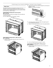
...is between 27⁵⁄₈" (70.2 cm) and 28⁵⁄₈" (72.7 cm) The oven feet do not need to position the feet for Multiple Cabinet Cutout Heights Single Ovens The positioning of your cabinet cutout. 2. They are positioned correctly as received. Using 2 or more people, ... surface. 5. In the same manner, remove the feet on its upright position. Using 2 or more people, place the oven on the right rear, left front, and left rear of the oven. 4. Remove the foot from the right front spacer by removing the #8-18 x ³⁄₈" screw. NOTE: ...
...is between 27⁵⁄₈" (70.2 cm) and 28⁵⁄₈" (72.7 cm) The oven feet do not need to position the feet for Multiple Cabinet Cutout Heights Single Ovens The positioning of your cabinet cutout. 2. They are positioned correctly as received. Using 2 or more people, ... surface. 5. In the same manner, remove the feet on its upright position. Using 2 or more people, place the oven on the right rear, left front, and left rear of the oven. 4. Remove the foot from the right front spacer by removing the #8-18 x ³⁄₈" screw. NOTE: ...
Installation Guide
Page 8
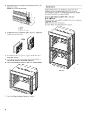
...remove, rotate and reinstall the feet on the right rear, left front, and left rear of the oven. Go to position the feet for the size of the oven feet allow a double oven to be installed in its upright position. NOTE: Do not remove the spacers. Reinstall the foot to...Electrical Connection" section. 4. 2. Rotate the foot 90° so the short side of the foot is positioned toward the top of the oven. 6. Double Ovens The positioning of your cabinet cutout. Spacer B. Cutout height is configured correctly as received. Spacers A A 7. Using 2 or more people, place the...
...remove, rotate and reinstall the feet on the right rear, left front, and left rear of the oven. Go to position the feet for the size of the oven feet allow a double oven to be installed in its upright position. NOTE: Do not remove the spacers. Reinstall the foot to...Electrical Connection" section. 4. 2. Rotate the foot 90° so the short side of the foot is positioned toward the top of the oven. 6. Double Ovens The positioning of your cabinet cutout. Spacer B. Cutout height is configured correctly as received. Spacers A A 7. Using 2 or more people, place the...
Installation Guide
Page 9
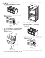
...;₈" screw. Spacer B. In the same manner, install a foot on a covered surface. 2. Spacer B. Using 2 or more people, place the oven on the left front spacer using a #8-18 x ³⁄₈" screw. NOTE: Position the foot so the short side of the foot is ...facing A toward the top of the oven. 4. A B C A. A B C A. Go to the "Make Electrical Connection" section. Foot C. #8-18 x ³⁄₈" screw 3. B C A. Install a foot ...
...;₈" screw. Spacer B. In the same manner, install a foot on a covered surface. 2. Spacer B. Using 2 or more people, place the oven on the left front spacer using a #8-18 x ³⁄₈" screw. NOTE: Position the foot so the short side of the foot is ...facing A toward the top of the oven. 4. A B C A. A B C A. Go to the "Make Electrical Connection" section. Foot C. #8-18 x ³⁄₈" screw 3. B C A. Install a foot ...
Installation Guide
Page 10
...these instructions can result in its upright position. Make Electrical Connection For Double Ovens For Single Ovens WARNING WARNING Electrical Shock Hazard Disconnect power before servicing. This oven is facing away from the oven as shown. 6. Use 8 gauge solid copper wire. Failure to follow these... foot B. #8-18 x ³⁄₈" screw C. Electrical Shock Hazard Disconnect power before servicing. Electrically ground oven. Using 2 or more people, place the oven in death, fire, or electrical shock. In the same manner, install a front foot on the left front ...
...these instructions can result in its upright position. Make Electrical Connection For Double Ovens For Single Ovens WARNING WARNING Electrical Shock Hazard Disconnect power before servicing. This oven is facing away from the oven as shown. 6. Use 8 gauge solid copper wire. Failure to follow these... foot B. #8-18 x ³⁄₈" screw C. Electrical Shock Hazard Disconnect power before servicing. Electrically ground oven. Using 2 or more people, place the oven in death, fire, or electrical shock. In the same manner, install a front foot on the left front ...
Installation Guide
Page 11
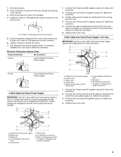
...;" (1.3 cm) 3-wire Cable from Home Power Supply ½" (1.3 cm) 4-Wire Cable from Home Power Supply IMPORTANT: Use the 4-wire cable from oven E. Connect the 2 red wires (C) together using a UL listed wire connector. 3. Red wires H. Connect the 2 white wires (D) and the green ...6. Connect the 2 red wires (G) together using a UL listed wire connector. 5. Junction box H I . White wires G. Route the flexible conduit from the oven to the green (or bare) ground wire (in Canada. Connect the 2 white wires (F) together using a UL listed wire connector. 4. Junction box C. White...
...;" (1.3 cm) 3-wire Cable from Home Power Supply ½" (1.3 cm) 4-Wire Cable from Home Power Supply IMPORTANT: Use the 4-wire cable from oven E. Connect the 2 red wires (C) together using a UL listed wire connector. 3. Red wires H. Connect the 2 white wires (D) and the green ...6. Connect the 2 red wires (G) together using a UL listed wire connector. 5. Junction box H I . White wires G. Route the flexible conduit from the oven to the green (or bare) ground wire (in Canada. Connect the 2 white wires (F) together using a UL listed wire connector. 4. Junction box C. White...
Installation Guide
Page 12
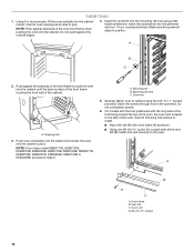
... B. Insert the grommet into the cabinet until the back surface of the front frame touches the front wall of the oven, the oven vent is taped to cabinet using a flatblade screwdriver. Push against the outside edges. 4. NOTE: If you have model ...KEBK171B, KEBK101B, KEBK276B, KEBK206B, KEBS179B, KEBS109B, KEBS277B, KEBS279B, KEBS207B, KEBS209B, KEBU109B or KEBU209B, proceed to push the oven into the mounting rail hole using the # 8-14 x 1" screws provided. A. Mounting rail B. A B D C A. Vent tab C. Shipping foot 3. See the...
... B. Insert the grommet into the cabinet until the back surface of the front frame touches the front wall of the oven, the oven vent is taped to cabinet using a flatblade screwdriver. Push against the outside edges. 4. NOTE: If you have model ...KEBK171B, KEBK101B, KEBK276B, KEBK206B, KEBS179B, KEBS109B, KEBS277B, KEBS279B, KEBS207B, KEBS209B, KEBU109B or KEBU209B, proceed to push the oven into the mounting rail hole using the # 8-14 x 1" screws provided. A. Mounting rail B. A B D C A. Vent tab C. Shipping foot 3. See the...
Installation Guide
Page 13
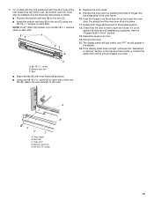
... E D C A. Rotate both hinge latches back to the vent (C) using two #8-18 x ¹⁄₄" screws on each side. See the "Prepare Built-In Oven" section. 13. Check that the door is used on each side. Vent tab C. See the following instructions to install. ■ Position the bottom vent trim (B) ... it is not, repeat the removal and installation procedures. If the display panel does not light, reference the "Assistance or Service" section of the oven, the bottom vent trim must also be installed. Vent ■ Align vent tab (B) with the short side of the foot toward the top of...
... E D C A. Rotate both hinge latches back to the vent (C) using two #8-18 x ¹⁄₄" screws on each side. See the "Prepare Built-In Oven" section. 13. Check that the door is used on each side. Vent tab C. See the following instructions to install. ■ Position the bottom vent trim (B) ... it is not, repeat the removal and installation procedures. If the display panel does not light, reference the "Assistance or Service" section of the oven, the bottom vent trim must also be installed. Vent ■ Align vent tab (B) with the short side of the foot toward the top of...
Installation Guide
Page 14
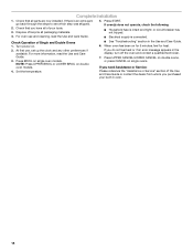
Dispose of the Use and Care Guide or contact the dealer from whom you do not feel for heat. Turn power on single ovens. If you need Assistance or Service: Please reference the "Assistance or Service" section of /recycle all parts are now installed. Check that you have all ... , set up the clock and any other preferences if available. NOTE: Press UPPER BROIL or LOWER BROIL on single oven models. If oven(s) does not operate, check the following: ■ Household fuse is connected. Press START. For more information, read the Use and Care Guide. 5. If there is ...
Dispose of the Use and Care Guide or contact the dealer from whom you do not feel for heat. Turn power on single ovens. If you need Assistance or Service: Please reference the "Assistance or Service" section of /recycle all parts are now installed. Check that you have all ... , set up the clock and any other preferences if available. NOTE: Press UPPER BROIL or LOWER BROIL on single oven models. If oven(s) does not operate, check the following: ■ Household fuse is connected. Press START. For more information, read the Use and Care Guide. 5. If there is ...
Energy Guide
Page 2
...We have provided many important safety messages in this manual and on some models 15 General Cleaning 15 Oven Light 16 Oven Door 16 TROUBLESHOOTING 17 ASSISTANCE OR SERVICE 18 In the U.S.A 18 Accessories 18 In Canada 18 WARRANTY ...don't follow instructions. TABLE OF CONTENTS OVEN SAFETY 2 PARTS AND FEATURES 4 ELECTRONIC OVEN CONTROLS 5 Display 5 Cancel 5 Oven Lights 5 Timer 5 Settings 6 Oven Temperature Control 7 Control Lockout 7 OVEN USE 8 Aluminum Foil 8 Positioning Racks and Bakeware 8 Bakeware 9 Meat Thermometer 9 Oven Vent(s 9 Baking 10 Broiling 10 ...
...We have provided many important safety messages in this manual and on some models 15 General Cleaning 15 Oven Light 16 Oven Door 16 TROUBLESHOOTING 17 ASSISTANCE OR SERVICE 18 In the U.S.A 18 Accessories 18 In Canada 18 WARRANTY ...don't follow instructions. TABLE OF CONTENTS OVEN SAFETY 2 PARTS AND FEATURES 4 ELECTRONIC OVEN CONTROLS 5 Display 5 Cancel 5 Oven Lights 5 Timer 5 Settings 6 Oven Temperature Control 7 Control Lockout 7 OVEN USE 8 Aluminum Foil 8 Positioning Racks and Bakeware 8 Bakeware 9 Meat Thermometer 9 Oven Vent(s 9 Baking 10 Broiling 10 ...
Energy Guide
Page 3
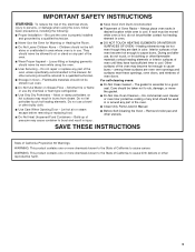
... Use Care When Opening Door - They should be used in or around any part of the oven. ■ Clean Only Parts Listed in injury. ■ Keep Oven Vent Ducts Unobstructed. ■ Placement of Oven Racks - Do not let potholder touch hot heating elements. Build-up of pressure may result in... not touch, or let clothing or other flammable materials contact heating elements or interior surfaces of oven until they are oven vent openings and surfaces near these openings, oven doors, and windows of oven doors. Do not use . Care should never be hot even though they have had sufficient ...
... Use Care When Opening Door - They should be used in or around any part of the oven. ■ Clean Only Parts Listed in injury. ■ Keep Oven Vent Ducts Unobstructed. ■ Placement of Oven Racks - Do not let potholder touch hot heating elements. Build-up of pressure may result in... not touch, or let clothing or other flammable materials contact heating elements or interior surfaces of oven until they are oven vent openings and surfaces near these openings, oven doors, and windows of oven doors. Do not use . Care should never be hot even though they have had sufficient ...
Energy Guide
Page 4
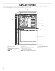
... have purchased may not match those of the items listed. Model and serial number plate (on double oven models) H. Lower oven (on center vent under control panel) D. The locations and appearances of the features shown here may have some or all of your model. Gasket F. Hidden ...
... have purchased may not match those of the items listed. Model and serial number plate (on double oven models) H. Lower oven (on center vent under control panel) D. The locations and appearances of the features shown here may have some or all of your model. Gasket F. Hidden ...
Energy Guide
Page 5
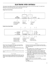
... the text display area. 3. Press TIMER SET/OFF to clear the display. Electronic display C. Settings J. Clean modes K. Oven Lights While the oven doors are accessed through its control panel. The time begins counting down in seconds. The locations and appearances of the items... shown here may have some or all of day. Temp/Time keypad C. ELECTRONIC OVEN CONTROLS This manual covers different models. Electronic display B. The Timer does not start the timer. "Press TIMER" will be set time. Clean ...
... the text display area. 3. Press TIMER SET/OFF to clear the display. Electronic display C. Settings J. Clean modes K. Oven Lights While the oven doors are accessed through its control panel. The time begins counting down in seconds. The locations and appearances of the items... shown here may have some or all of day. Temp/Time keypad C. ELECTRONIC OVEN CONTROLS This manual covers different models. Electronic display B. The Timer does not start the timer. "Press TIMER" will be set time. Clean ...


