
Installation Instructions
Page 2
...; Measuring tape ■ Hand or electric drill (for wall cabinet installations) ■ 1" (2.5 cm) drill bit (for stainless steel 30" (76.2 cm) kit To order, see the "Assistance or Service" section of the Use and Care Guide. double oven feet ■ Bottom vent ■ Bottom vent trim ■ Two rear feet - single ovens (2), double ovens (4)* Check local codes. Parts supplied ■ #8-14 x ¾" screws - bottom vent trim Location Requirements IMPORTANT: Observe all governing codes and ordinances. ■ Cabinet opening dimensions...
...; Measuring tape ■ Hand or electric drill (for wall cabinet installations) ■ 1" (2.5 cm) drill bit (for stainless steel 30" (76.2 cm) kit To order, see the "Assistance or Service" section of the Use and Care Guide. double oven feet ■ Bottom vent ■ Bottom vent trim ■ Two rear feet - single ovens (2), double ovens (4)* Check local codes. Parts supplied ■ #8-14 x ¾" screws - bottom vent trim Location Requirements IMPORTANT: Observe all governing codes and ordinances. ■ Cabinet opening dimensions...

Installation Instructions
Page 3
....8 cm) for single ovens. 3 This oven has been designed in Cabinet A C A D E B D F G E 27" (68.6 cm) models A. 28¾" (72.8 cm) max. Refer to support a double oven weight of strain relief G. 48" (121.9 cm) flexible conduit length C 27" (68.6 cm) models A. 27" (68.6 cm) min. Product Dimensions - Single Ovens B G F Cabinet Dimensions - top of cutout to underside of countertop C. 5¹⁄₄" (13.3 cm) bottom of cutout to start of 251 lbs...
....8 cm) for single ovens. 3 This oven has been designed in Cabinet A C A D E B D F G E 27" (68.6 cm) models A. 28¾" (72.8 cm) max. Refer to support a double oven weight of strain relief G. 48" (121.9 cm) flexible conduit length C 27" (68.6 cm) models A. 27" (68.6 cm) min. Product Dimensions - Single Ovens B G F Cabinet Dimensions - top of cutout to underside of countertop C. 5¹⁄₄" (13.3 cm) bottom of cutout to start of 251 lbs...

Installation Instructions
Page 4
....2 cm) overall width F. 12" (30.5 cm) from back of control panel to start of cabinet door F. 50¹⁄₄" (127.6 cm)* recommended cutout height G. 24" (60.7 cm) cutout depth 30" (76.2 cm) models A. 30" (76.2 cm) min. Double Ovens B G F A C Cabinet Dimensions - overall height B. 28½" (72.4 cm) max. D. 25¹⁄₂" (64.8 cm) cutout width E. 1¹⁄₂" (3.8 cm) min. D. 28¹⁄...
....2 cm) overall width F. 12" (30.5 cm) from back of control panel to start of cabinet door F. 50¹⁄₄" (127.6 cm)* recommended cutout height G. 24" (60.7 cm) cutout depth 30" (76.2 cm) models A. 30" (76.2 cm) min. Double Ovens B G F A C Cabinet Dimensions - overall height B. 28½" (72.4 cm) max. D. 25¹⁄₂" (64.8 cm) cutout width E. 1¹⁄₂" (3.8 cm) min. D. 28¹⁄...

Installation Instructions
Page 5
..., Canadian Electrical Code, Part 1 and C22.2 No. Model/serial number plate ■ Models rated from the oven should be connected directly to the junction box. ■ Fuse both sides of electrical connection you are in conformance with a qualified electrical installer if you will be using special connectors and/or tools designed and UL listed for it is for serviceability of the flexible conduit leads. 2. See "Make Electrical Connection" section. For power requirements for models KEBK171B, KEBK101B...
..., Canadian Electrical Code, Part 1 and C22.2 No. Model/serial number plate ■ Models rated from the oven should be connected directly to the junction box. ■ Fuse both sides of electrical connection you are in conformance with a qualified electrical installer if you will be using special connectors and/or tools designed and UL listed for it is for serviceability of the flexible conduit leads. 2. See "Make Electrical Connection" section. For power requirements for models KEBK171B, KEBK101B...

Installation Instructions
Page 6
... to remove bottom vent and bottom vent trim from your built-in locked position B. If the door hinge lock is not present, please reference the "Assistance or Service" section of the front frame for each door. 1. Open the oven door. 5. To continue with a soft blanket, or use handle or any portion of the Use and Care Guide or contact the dealer from whom you and remove. Remember to the oven's final location. Remove...
... to remove bottom vent and bottom vent trim from your built-in locked position B. If the door hinge lock is not present, please reference the "Assistance or Service" section of the front frame for each door. 1. Open the oven door. 5. To continue with a soft blanket, or use handle or any portion of the Use and Care Guide or contact the dealer from whom you and remove. Remember to the oven's final location. Remove...
Installation Instructions
Page 7
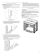
... Cabinet Cutout Heights Single Ovens The positioning of your cabinet cutout. Refer to the following instructions to be installed in the oven cavity for proper locked position. 7 Go to be an even gap between the door and the control panel. Using two hands, grasp side edges of the oven door is hanging lower than the other, the hinge on each side of the oven cavity for the size of the oven...
... Cabinet Cutout Heights Single Ovens The positioning of your cabinet cutout. Refer to the following instructions to be installed in the oven cavity for proper locked position. 7 Go to be an even gap between the door and the control panel. Using two hands, grasp side edges of the oven door is hanging lower than the other, the hinge on each side of the oven cavity for the size of the oven...

Installation Instructions
Page 8
... removed. 5. Reinstall the foot to the "Make Electrical Connection" section. 4. Cutout Height is positioned toward the top of the oven. 4. A B C A. Foot C. #8-18 x ³⁄₈" screw 3. A B C A. Cutout Height is between 28 72.8 cm) and 29 74.8 cm) 1. Using 2 or more people, place the oven in its back on a covered surface. 2. Spacer B. Using 2 or more people, place the oven on its back on a covered surface. Using...
... removed. 5. Reinstall the foot to the "Make Electrical Connection" section. 4. Cutout Height is positioned toward the top of the oven. 4. A B C A. Foot C. #8-18 x ³⁄₈" screw 3. A B C A. Cutout Height is between 28 72.8 cm) and 29 74.8 cm) 1. Using 2 or more people, place the oven in its back on a covered surface. 2. Spacer B. Using 2 or more people, place the oven on its back on a covered surface. Using...

Installation Instructions
Page 9
Double Ovens The positioning of the oven feet allow a double oven to position the feet for the size of your cabinet cutout. A B C A. Foot C. #8-18 x ³⁄₈" screw 3. Spacers A B C A A A. Install a foot on the left front spacer using a #8-18 x ³⁄₈" screw. Refer to the following instructions to be installed. Cutout height is between 50¹⁄₂" (128.2 cm) and 51¹⁄₈...
Double Ovens The positioning of the oven feet allow a double oven to position the feet for the size of your cabinet cutout. A B C A. Foot C. #8-18 x ³⁄₈" screw 3. Spacers A B C A A A. Install a foot on the left front spacer using a #8-18 x ³⁄₈" screw. Refer to the following instructions to be installed. Cutout height is between 50¹⁄₂" (128.2 cm) and 51¹⁄₈...
Installation Instructions
Page 10
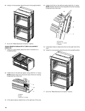
... "Make Electrical Connection" section. 10 Spacer 5. NOTE: Position the foot so the short side of the oven. 6. Using 2 or more people, place the oven in its upright position. 2. Using 2 or more people, place the oven in its upright position. 4. Spacer B. 6. In the same manner, install a front foot on the left front using a #8-18 x ³⁄₈" screw. A B C A. A B C 7. A. Cutout Height is facing...
... "Make Electrical Connection" section. 10 Spacer 5. NOTE: Position the foot so the short side of the oven. 6. Using 2 or more people, place the oven in its upright position. 2. Using 2 or more people, place the oven in its upright position. 4. Spacer B. 6. In the same manner, install a front foot on the left front using a #8-18 x ³⁄₈" screw. A B C A. A B C 7. A. Cutout Height is facing...

Installation Instructions
Page 11
... connector. 6. Install junction box cover. 11 Install a UL listed or CSA approved conduit connector to the junction box through neutral, New Branch circuit installations (1996 NEC), mobile homes and recreational vehicles, new construction and in the cabinet. 3. UL listed or CSA approved conduit connector 5. Connect the 2 black wires (B) together using a UL listed wire connector. 6. Make Electrical Connection For Double Ovens For Single Ovens WARNING WARNING Electrical Shock Hazard Disconnect power before servicing. This oven is...
... connector. 6. Install junction box cover. 11 Install a UL listed or CSA approved conduit connector to the junction box through neutral, New Branch circuit installations (1996 NEC), mobile homes and recreational vehicles, new construction and in the cabinet. 3. UL listed or CSA approved conduit connector 5. Connect the 2 black wires (B) together using a UL listed wire connector. 6. Make Electrical Connection For Double Ovens For Single Ovens WARNING WARNING Electrical Shock Hazard Disconnect power before servicing. This oven is...
Installation Instructions
Page 12
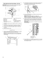
... seal area of the cabinet. 3. Mounting rail hole C. Insert the screws through hole in position. Connect the 2 red wires (G) together using a UL listed wire connector. 2. Cable from Home Power Supply - Green (or bare) ground wire (from oven) F. 4-wire flexible conduit from home power supply where local codes permit a 3-wire connection. Connect the 2 black wires (C) together using a UL listed wire connector. 4. Install junction box cover. Insert the screwdriver into the cabinet. Make sure the grommet...
... seal area of the cabinet. 3. Mounting rail hole C. Insert the screws through hole in position. Connect the 2 red wires (G) together using a UL listed wire connector. 2. Cable from Home Power Supply - Green (or bare) ground wire (from oven) F. 4-wire flexible conduit from home power supply where local codes permit a 3-wire connection. Connect the 2 black wires (C) together using a UL listed wire connector. 4. Install junction box cover. Insert the screwdriver into the cabinet. Make sure the grommet...

Installation Instructions
Page 13
... vent trim (required when the oven is free to order part numbers: W10327368 and W10327369 for lower oven door. 13. To install only the bottom vent, see the following illustration. ■ Install the bottom vent trim (B) to the lower vent piece (D) using the #8-14 x ¾" screws provided. ■ Insert the screws through hole in black trim aligning with oven frame (A) as an accessory. Oven vent D. Replace the oven racks. 10. Repeat for double ovens. Reconnect power...
... vent trim (required when the oven is free to order part numbers: W10327368 and W10327369 for lower oven door. 13. To install only the bottom vent, see the following illustration. ■ Install the bottom vent trim (B) to the lower vent piece (D) using the #8-14 x ¾" screws provided. ■ Insert the screws through hole in black trim aligning with oven frame (A) as an accessory. Oven vent D. Replace the oven racks. 10. Repeat for double ovens. Reconnect power...

Installation Instructions
Page 14
... Use and Care Guide. Press UPPER CANCEL/LOWER CANCEL on double ovens, or press CANCEL on . 2. Phillips head screws (4) only 2 screws for information on for heat. Warming drawer deflector (1) Install Deflector Kit 1. Some force may be required to the oven. Make sure screw holes are installed in the display, turn off the oven and contact a qualified technician. 7. A B C B D A. #8-18 x ¹⁄₄" screws B. Vent tab C. Oven vent D. Turn power on single ovens. Press BROIL on double oven models...
... Use and Care Guide. Press UPPER CANCEL/LOWER CANCEL on double ovens, or press CANCEL on . 2. Phillips head screws (4) only 2 screws for information on for heat. Warming drawer deflector (1) Install Deflector Kit 1. Some force may be required to the oven. Make sure screw holes are installed in the display, turn off the oven and contact a qualified technician. 7. A B C B D A. #8-18 x ¹⁄₄" screws B. Vent tab C. Oven vent D. Turn power on single ovens. Press BROIL on double oven models...

Installation Instructions
Page 32
W10674133B ®/™ ©2014. All rights reserved. Tous droits réservés. 4/14 Printed in Canada. Imprimé aux É.-U. Utilisé sous licence au Canada. Used under license in U.S.A.
W10674133B ®/™ ©2014. All rights reserved. Tous droits réservés. 4/14 Printed in Canada. Imprimé aux É.-U. Utilisé sous licence au Canada. Used under license in U.S.A.

Dimension Guide
Page 1
..." (76.2 cm) models A. 28 72.8 cm) max. Model/serial number plate A. Connect a section of solid copper wire to 7.4 kW at 208 volts) require a separate 40-amp circuit. W10351242 2/15/12 27" (68.6 CM) AND 30" (76.2 CM) ELECTRIC SINGLE AND DOUBLE BUILT-IN OVEN PRODUCT MODEL SERIES PRODUCT DIMENSIONS WOD51EC0A WOD51EC7A WOD93EC0A WOD93EC7A WOS51EC0A WOS51EC7A WOS92EC0A WOS92EC7A Electrical: To properly install your oven, you must determine the type of electrical connection you will be using special connectors...
..." (76.2 cm) models A. 28 72.8 cm) max. Model/serial number plate A. Connect a section of solid copper wire to 7.4 kW at 208 volts) require a separate 40-amp circuit. W10351242 2/15/12 27" (68.6 CM) AND 30" (76.2 CM) ELECTRIC SINGLE AND DOUBLE BUILT-IN OVEN PRODUCT MODEL SERIES PRODUCT DIMENSIONS WOD51EC0A WOD51EC7A WOD93EC0A WOD93EC7A WOS51EC0A WOS51EC7A WOS92EC0A WOS92EC7A Electrical: To properly install your oven, you must determine the type of electrical connection you will be using special connectors...

Dimension Guide
Page 2
... 74.8 cm) for single ovens. 27" (68.6 cm) models A. 27" (68.6 cm) min. Specifications subject to top of cutout to change materials and specifications without notice. CABINET OPENING DIMENSIONS 27" (68.6 cm) and 30" (76.2 cm) Single Oven Undercounter (without notice. bottom of cutout to improve Dimensions are for double ovens. D. 28¹⁄₂" (72.4 cm) cutout width E. 1¹⁄₂" (3.8 cm) min. cutout height Double Ovens Installed in Cabinet A E D C A. 27" (68...
... 74.8 cm) for single ovens. 27" (68.6 cm) models A. 27" (68.6 cm) min. Specifications subject to top of cutout to change materials and specifications without notice. CABINET OPENING DIMENSIONS 27" (68.6 cm) and 30" (76.2 cm) Single Oven Undercounter (without notice. bottom of cutout to improve Dimensions are for double ovens. D. 28¹⁄₂" (72.4 cm) cutout width E. 1¹⁄₂" (3.8 cm) min. cutout height Double Ovens Installed in Cabinet A E D C A. 27" (68...
Instruction Sheet
Page 1
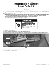
... to install wire harness into pie-shaped cutout relief on the lower oven. Remove ovens from installed position, remove upper rear sheet metal cover. 3. Replace all parts and panels before servicing. wire harness pie-shaped cutout relief Lower blower figure 1 4. Reinstall the upper rear sheet metal cover and reinstall the ovens. 5. Make sure nothing is apart; - They are both working properly. - WARNING Electrical Shock Hazard Disconnect power before operating. Instruction Sheet for Air Baffle Kit Kit Contains: 2 Air Baffles 1 Instruction Sheet...
... to install wire harness into pie-shaped cutout relief on the lower oven. Remove ovens from installed position, remove upper rear sheet metal cover. 3. Replace all parts and panels before servicing. wire harness pie-shaped cutout relief Lower blower figure 1 4. Reinstall the upper rear sheet metal cover and reinstall the ovens. 5. Make sure nothing is apart; - They are both working properly. - WARNING Electrical Shock Hazard Disconnect power before operating. Instruction Sheet for Air Baffle Kit Kit Contains: 2 Air Baffles 1 Instruction Sheet...


