Installation Guide
Page 1
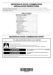
...seriously injured if you don't immediately follow the safety alert symbol and either the word "DANGER" or "WARNING." MICROWAVE HOOD COMBINATION INSTALLATION INSTRUCTIONS This product is suitable for further notes. This is the safety alert symbol. Table of ... cover different models. We have provided many important safety messages in Rear Wall 7 Attach Mounting Plate to reduce the chance of Contents MICROWAVE HOOD COMBINATION SAFETY 1 INSTALLATION REQUIREMENTS 2 Tools and Parts 2 Remove Cardboard Template 2 Location Requirements 2 Product Dimensions 3 Electrical Requirements 3...
...seriously injured if you don't immediately follow the safety alert symbol and either the word "DANGER" or "WARNING." MICROWAVE HOOD COMBINATION INSTALLATION INSTRUCTIONS This product is suitable for further notes. This is the safety alert symbol. Table of ... cover different models. We have provided many important safety messages in Rear Wall 7 Attach Mounting Plate to reduce the chance of Contents MICROWAVE HOOD COMBINATION SAFETY 1 INSTALLATION REQUIREMENTS 2 Tools and Parts 2 Remove Cardboard Template 2 Location Requirements 2 Product Dimensions 3 Electrical Requirements 3...
Installation Guide
Page 2
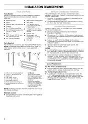
...-head bolts (2) B. 1/4-20 x 3" flat-head bolts (2) C. Sheet metal screws (2) G. Power supply cord bushing (1) H. Cut along the perforation to exist above the microwave oven so that the materials used will be combined. See "Installation Dimensions" illustration. ■ Minimum one 2" x 4" (50.8 x 101.6 mm) wood wall stud and...using a rectangular to round transition piece, the 3" (7.6 cm) clearance needs to separate the template from the top of the microwave oven packaging is at least 6" (15.2 cm) of the cardboard packaging. 2. See User Instructions.) NOTE: Depending on ...
...-head bolts (2) B. 1/4-20 x 3" flat-head bolts (2) C. Sheet metal screws (2) G. Power supply cord bushing (1) H. Cut along the perforation to exist above the microwave oven so that the materials used will be combined. See "Installation Dimensions" illustration. ■ Minimum one 2" x 4" (50.8 x 101.6 mm) wood wall stud and...using a rectangular to round transition piece, the 3" (7.6 cm) clearance needs to separate the template from the top of the microwave oven packaging is at least 6" (15.2 cm) of the cardboard packaging. 2. See User Instructions.) NOTE: Depending on ...
Installation Guide
Page 3
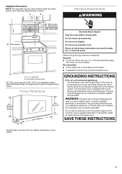
... Do not use an extension cord. Recommended: ■ A time-delay fuse or time-delay circuit breaker. ■ A separate circuit serving only this microwave oven. The plug must be inside the upper cabinet. Do not use an adapter. Required: ■ A 120 volt, 60 Hz, AC only, 15-...supply cord is equipped with a cord having a grounding wire with a fuse or circuit breaker. Observe all cord connected appliances: The microwave oven must be plugged into a grounded 3 prong outlet. Consult a qualified electrician or serviceman if the grounding instructions are not completely ...
... Do not use an extension cord. Recommended: ■ A time-delay fuse or time-delay circuit breaker. ■ A separate circuit serving only this microwave oven. The plug must be inside the upper cabinet. Do not use an adapter. Required: ■ A 120 volt, 60 Hz, AC only, 15-...supply cord is equipped with a cord having a grounding wire with a fuse or circuit breaker. Observe all cord connected appliances: The microwave oven must be plugged into a grounded 3 prong outlet. Consult a qualified electrician or serviceman if the grounding instructions are not completely ...
Installation Guide
Page 4
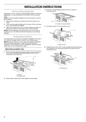
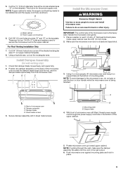
...Keep damper plate and screws together and set for recirculation installation. If the mounting plate is attached to the microwave oven, do not grip or use the door or door handle while the microwave oven is set aside. 4 A A. For wall or roof venting, changes must be made to the... the mounting plate may be in the foam packaging, or it aside. 3. NOTE: To avoid possible damage to back of microwave oven exterior. Remove any remaining contents from the microwave oven cavity. 2. Remove 2 screws attaching blower motor to the work surface, cover the work surface. 1. Lift blower motor ...
...Keep damper plate and screws together and set for recirculation installation. If the mounting plate is attached to the microwave oven, do not grip or use the door or door handle while the microwave oven is set aside. 4 A A. For wall or roof venting, changes must be made to the... the mounting plate may be in the foam packaging, or it aside. 3. NOTE: To avoid possible damage to back of microwave oven exterior. Remove any remaining contents from the microwave oven cavity. 2. Remove 2 screws attaching blower motor to the work surface, cover the work surface. 1. Lift blower motor ...
Installation Guide
Page 5
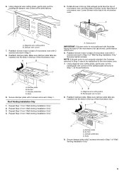
... blower motor to back of "Wall Venting Installation Only." 5 A B C A. Damper plate B. Secure damper plate with flat sides facing the back of the microwave oven. Repeat Step 3 from "Wall Venting Installation Only." 3. AB A. A A B A. Securely tighten screws. Repeat Step 1 from "Wall Venting Installation Only...." Make sure damper plate tabs are inserted into the slots in the top of the microwave oven. Make sure damper plate tabs are inserted into the slots in Step 3 cannot be poor. 6. Slots 9. 6. Exhaust ...
... blower motor to back of "Wall Venting Installation Only." 5 A B C A. Damper plate B. Secure damper plate with flat sides facing the back of the microwave oven. Repeat Step 3 from "Wall Venting Installation Only." 3. AB A. A A B A. Securely tighten screws. Repeat Step 1 from "Wall Venting Installation Only...." Make sure damper plate tabs are inserted into the slots in the top of the microwave oven. Make sure damper plate tabs are inserted into the slots in Step 3 cannot be poor. 6. Slots 9. 6. Exhaust ...
Installation Guide
Page 6
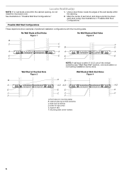
...(s) NOTE: If no wall studs exist within the cabinet opening vertical centerline C. See illustrations in "Possible Wall Stud Configurations." Cabinet opening , do not install the microwave oven. 1. Support tabs F. Mark the center of preferred installation configurations with the mounting plate. Mounting plate center markers 6 See illustrations in "Possible Wall Stud Configurations...
...(s) NOTE: If no wall studs exist within the cabinet opening vertical centerline C. See illustrations in "Possible Wall Stud Configurations." Cabinet opening , do not install the microwave oven. 1. Support tabs F. Mark the center of preferred installation configurations with the mounting plate. Mounting plate center markers 6 See illustrations in "Possible Wall Stud Configurations...
Installation Guide
Page 7
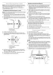
... a minimum of 1 wall stud, preferably 2, using a minimum of 1 lag screw, preferably 2. 1. These represent the mounting plate's end holes and bottom edge. 4. Mark Rear Wall The microwave oven must be on a level line with front edge of cabinet. Draw the 2 vertical, plumb lines down from the centerline. 5.
... a minimum of 1 wall stud, preferably 2, using a minimum of 1 lag screw, preferably 2. 1. These represent the mounting plate's end holes and bottom edge. 4. Mark Rear Wall The microwave oven must be on a level line with front edge of cabinet. Draw the 2 vertical, plumb lines down from the centerline. 5.
Installation Guide
Page 8
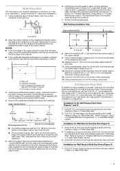
...the lag screws. Remove all lag screws and bolts. The template has trim lines to use as guides. ■ If the wall behind the microwave oven (as at both end holes of mounting plate, making sure it is maintained. Push the 2 bolts with the holes in Rear Wall"... mounting plate. 2. Prepare Upper Cabinet 1. Push the bolt with the vertical centerline on the wall. 2. Insert a lag screw into wall stud(s) in Step 2 of the microwave oven. Drywall 5. Disconnect power to go through both ends. 1. Upper-cabinet template D 10" (25.4 cm) F E 10" G (25.4 cm) 8 Attach Mounting ...
...the lag screws. Remove all lag screws and bolts. The template has trim lines to use as guides. ■ If the wall behind the microwave oven (as at both end holes of mounting plate, making sure it is maintained. Push the 2 bolts with the holes in Rear Wall"... mounting plate. 2. Prepare Upper Cabinet 1. Push the bolt with the vertical centerline on the wall. 2. Insert a lag screw into wall stud(s) in Step 2 of the microwave oven. Drywall 5. Disconnect power to go through both ends. 1. Upper-cabinet template D 10" (25.4 cm) F E 10" G (25.4 cm) 8 Attach Mounting ...
Installation Guide
Page 9
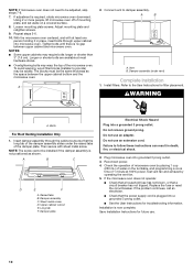
... on the back of the shaded rectangular area "F" on Upper Cabinet Template. 8. Handle the microwave oven gently. 1. Secure damper assembly with 2 sheet metal screws. With front of microwave oven still tilted, thread power supply cord through the wall, make sure the damper assembly fits... Mounting plate B. Support tabs 4. Using a keyhole saw, cut out the rectangular area. Damper assembly C. Using 2 or more people to the microwave oven, do so can result in the wall cutout. 6. These are for the power supply cord. Place a washer on support tabs at points...
... on the back of the shaded rectangular area "F" on Upper Cabinet Template. 8. Handle the microwave oven gently. 1. Secure damper assembly with 2 sheet metal screws. With front of microwave oven still tilted, thread power supply cord through the wall, make sure the damper assembly fits... Mounting plate B. Support tabs 4. Using a keyhole saw, cut out the rectangular area. Damper assembly C. Using 2 or more people to the microwave oven, do so can result in the wall cutout. 6. These are for the power supply cord. Place a washer on support tabs at points...
Installation Guide
Page 10
... these instructions can result in place, insert bolts through the cabinet cutout so that a circuit breaker has not tripped. If the microwave oven does not operate: ■ Check that a household fuse has not blown, or that the long tab of the damper... Long tab F. If the problem continues, call an electrician. ■ Check that the power supply cord is plugged into a grounded 3 prong outlet. With the microwave oven centered, and with sheet metal screw. NOTE: The screw cannot be adjusted, skip steps 7-9. 7. Sheet metal screw D. Test vent fan and exhaust by placing...
... these instructions can result in place, insert bolts through the cabinet cutout so that a circuit breaker has not tripped. If the microwave oven does not operate: ■ Check that a household fuse has not blown, or that the long tab of the damper... Long tab F. If the problem continues, call an electrician. ■ Check that the power supply cord is plugged into a grounded 3 prong outlet. With the microwave oven centered, and with sheet metal screw. NOTE: The screw cannot be adjusted, skip steps 7-9. 7. Sheet metal screw D. Test vent fan and exhaust by placing...
Installation Guide
Page 11
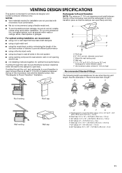
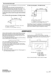
... is used, be sure there is at least 3" (7.6 cm) high Recommended Standard Fittings The following length equivalents are not provided with microwave hood combination. ■ We do not recommend using caulking compound to seal exterior wall or roof opening around cap ■ not installing...venting through the wall, be sure to round transition piece F. Vent extension piece, at least 3" (7.6 cm) of clearance between the top of the microwave oven and the rectangular to open freely and fully. Rectangular to round transition piece: 3¹⁄₄" x 10" to 6" = 5 ft (8.3 ...
... is used, be sure there is at least 3" (7.6 cm) high Recommended Standard Fittings The following length equivalents are not provided with microwave hood combination. ■ We do not recommend using caulking compound to seal exterior wall or roof opening around cap ■ not installing...venting through the wall, be sure to round transition piece F. Vent extension piece, at least 3" (7.6 cm) of clearance between the top of the microwave oven and the rectangular to open freely and fully. Rectangular to round transition piece: 3¹⁄₄" x 10" to 6" = 5 ft (8.3 ...
Installation Guide
Page 12
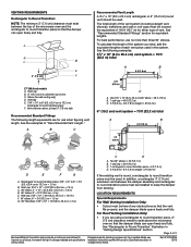
...to round transition piece must be installed to keep the damper from your model number located on the front frame of the microwave oven. Replacement Parts If any of the installation hardware needs to round transition piece must not exceed the equivalent of 140 ft... of vent. All rights reserved. 8/14 Printed in pairs. When you call, you will need , add the equivalent lengths of the system you need the microwave oven model number and serial number. See the following examples: 3¹⁄₄" x 10" (8.3 x 25.4 cm) vent system = 73 ft (22.2 m) total A B 6 ft ...
...to round transition piece must be installed to keep the damper from your model number located on the front frame of the microwave oven. Replacement Parts If any of the installation hardware needs to round transition piece must not exceed the equivalent of 140 ft... of vent. All rights reserved. 8/14 Printed in pairs. When you call, you will need , add the equivalent lengths of the system you need the microwave oven model number and serial number. See the following examples: 3¹⁄₄" x 10" (8.3 x 25.4 cm) vent system = 73 ft (22.2 m) total A B 6 ft ...
Dimension Guide
Page 1
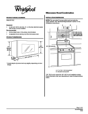
..., 60 Hz, AC only, 15- A B 30" (76.2 cm) min. Recommended: • A time-delay fuse or time-delay circuit breaker. • A separate circuit serving only this microwave oven. upper cabinet and side cabinet depth 17¹⁄₈" (43.5 cm) (0.5 cm) 16¹⁄₄" (41.3 cm) 66" (167.6 cm) min. (42...
..., 60 Hz, AC only, 15- A B 30" (76.2 cm) min. Recommended: • A time-delay fuse or time-delay circuit breaker. • A separate circuit serving only this microwave oven. upper cabinet and side cabinet depth 17¹⁄₈" (43.5 cm) (0.5 cm) 16¹⁄₄" (41.3 cm) 66" (167.6 cm) min. (42...
Dimension Guide
Page 2
...to round transition piece must be installed to change without notice. See the following length equivalents are for either type of the microwave oven and the . Ref. See "Rectangular to without notice. change materials and specifications Installation Instructions packed with product. In ... 05/15 rectangular to exist above the microwave oven so that the damper . A B C Recommended Vent Length A 31⁄4" x 10" (8.3 x 25.4 cm) rectangular or 6" (15.2 cm) round vent should be free of 2 Because Whirlpool Corporation policy includes a continuous commitment to ...
...to round transition piece must be installed to change without notice. See the following length equivalents are for either type of the microwave oven and the . Ref. See "Rectangular to without notice. change materials and specifications Installation Instructions packed with product. In ... 05/15 rectangular to exist above the microwave oven so that the damper . A B C Recommended Vent Length A 31⁄4" x 10" (8.3 x 25.4 cm) rectangular or 6" (15.2 cm) round vent should be free of 2 Because Whirlpool Corporation policy includes a continuous commitment to ...


