Installation Guide
Page 1
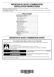
... for further notes. The appearance of injury, and tell you what the potential hazard is the safety alert symbol. W10724870A Table of Contents MICROWAVE HOOD COMBINATION SAFETY 1 INSTALLATION REQUIREMENTS 2 Tools and Parts 2 Remove Cardboard Template 2 Location Requirements 2 Product Dimensions 3 Electrical Requirements 3 INSTALLATION INSTRUCTIONS 4 Remove Mounting Plate 4 Rotate Blower Motor 4 Locate Wall Stud(s 6 Mark Rear Wall 7 Drill Holes in these installation instructions. Always read and obey all safety messages. This is , tell you don't follow...
... for further notes. The appearance of injury, and tell you what the potential hazard is the safety alert symbol. W10724870A Table of Contents MICROWAVE HOOD COMBINATION SAFETY 1 INSTALLATION REQUIREMENTS 2 Tools and Parts 2 Remove Cardboard Template 2 Location Requirements 2 Product Dimensions 3 Electrical Requirements 3 INSTALLATION INSTRUCTIONS 4 Remove Mounting Plate 4 Rotate Blower Motor 4 Locate Wall Stud(s 6 Mark Rear Wall 7 Drill Holes in these installation instructions. Always read and obey all safety messages. This is , tell you don't follow...
Installation Guide
Page 2
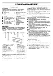
...) clearance needs to it during the "Mark Rear Wall" part of 150 lbs (68 kg), which includes microwave oven and items placed inside the microwave oven and upper cabinet. ■ Grounded electrical outlet inside the perforation is perforated. Power supply cord bushing (1) H. The piece inside upper cabinet. Set the cardboard template to the side and refer to exist above the microwave oven so that the materials used will be free of packaging) Aluminum grease filters Charcoal filters...
...) clearance needs to it during the "Mark Rear Wall" part of 150 lbs (68 kg), which includes microwave oven and items placed inside the microwave oven and upper cabinet. ■ Grounded electrical outlet inside the perforation is perforated. Power supply cord bushing (1) H. The piece inside upper cabinet. Set the cardboard template to the side and refer to exist above the microwave oven so that the materials used will be free of packaging) Aluminum grease filters Charcoal filters...
Installation Guide
Page 3
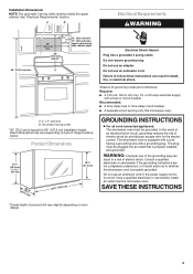
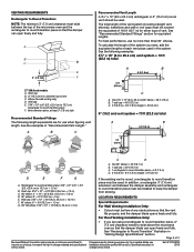
... range/cooktop below. Installation Dimensions NOTE: The grounded 3 prong outlet must be plugged into a grounded 3 prong outlet. upper cabinet and side cabinet depth A. 2" x 4" wall stud B. If the power supply cord is properly grounded. Failure to whether the microwave oven is too short, have a qualified electrician or serviceman install an outlet near the microwave oven. GROUNDING INSTRUCTIONS ■ For all governing codes and ordinances. Do not use of electric...
... range/cooktop below. Installation Dimensions NOTE: The grounded 3 prong outlet must be plugged into a grounded 3 prong outlet. upper cabinet and side cabinet depth A. 2" x 4" wall stud B. If the power supply cord is properly grounded. Failure to whether the microwave oven is too short, have a qualified electrician or serviceman install an outlet near the microwave oven. GROUNDING INSTRUCTIONS ■ For all governing codes and ordinances. Do not use of electric...
Installation Guide
Page 4
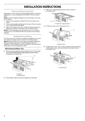
... location where wall or roof venting may be used. Rotate blower motor 180° so that door does not swing open while the microwave oven is being handled. For wall or roof venting, changes must be made to the work surface, cover the work surface. 1. A B A. Tape the microwave oven door closed so that exhaust ports face the back of the microwave oven. Screws B. Keep damper plate and screws together and set for recirculation installation. Damper plate 2. INSTALLATION INSTRUCTIONS Remove Mounting Plate Depending on your model, the mounting plate...
... location where wall or roof venting may be used. Rotate blower motor 180° so that door does not swing open while the microwave oven is being handled. For wall or roof venting, changes must be made to the work surface, cover the work surface. 1. A B A. Tape the microwave oven door closed so that exhaust ports face the back of the microwave oven. Screws B. Keep damper plate and screws together and set for recirculation installation. Damper plate 2. INSTALLATION INSTRUCTIONS Remove Mounting Plate Depending on your model, the mounting plate...
Installation Guide
Page 5
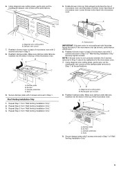
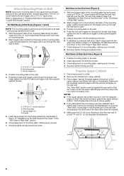
... blower motor to the microwave oven. 7. Repeat Step 3 from "Wall Venting Installation Only." Diagonal wire cutting pliers B. Slots 9. Using diagonal wire cutting pliers, gently snip out the rectangular damper vent covers at the perforations. Repeat Step 4 from "Wall Venting Installation Only." 4. Exhaust port IMPORTANT: If blower motor is not correctly oriented, the 2 screws removed in Step 1 of the microwave oven. Damper plate B. Repeat Step 1 from "Wall Venting Installation Only." 3. Screws C. Damper plate tabs D. Secure damper plate with 2 screws removed in...
... blower motor to the microwave oven. 7. Repeat Step 3 from "Wall Venting Installation Only." Diagonal wire cutting pliers B. Slots 9. Using diagonal wire cutting pliers, gently snip out the rectangular damper vent covers at the perforations. Repeat Step 4 from "Wall Venting Installation Only." 4. Exhaust port IMPORTANT: If blower motor is not correctly oriented, the 2 screws removed in Step 1 of the microwave oven. Damper plate B. Repeat Step 1 from "Wall Venting Installation Only." 3. Screws C. Damper plate tabs D. Secure damper plate with 2 screws removed in...
Installation Guide
Page 6
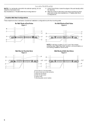
... Holes Figure 2 B C C C D B D A A A A E E E E F F NOTE: If wall stud is within 6" (15.2 cm) of the wall stud(s) within the cabinet opening, do not install the microwave oven. 1. End holes (on mounting plate) B. Cabinet opening vertical centerline C. Wall stud centerlines D. Support tabs F. Holes for lag screws E. Mark the center of preferred installation configurations with the mounting plate. See illustrations in "Possible Wall Stud Configurations." Locate Wall Stud(s) NOTE: If no wall studs exist within the...
... Holes Figure 2 B C C C D B D A A A A E E E E F F NOTE: If wall stud is within 6" (15.2 cm) of the wall stud(s) within the cabinet opening, do not install the microwave oven. 1. End holes (on mounting plate) B. Cabinet opening vertical centerline C. Wall stud centerlines D. Support tabs F. Holes for lag screws E. Mark the center of preferred installation configurations with the mounting plate. See illustrations in "Possible Wall Stud Configurations." Locate Wall Stud(s) NOTE: If no wall studs exist within the...
Installation Guide
Page 7
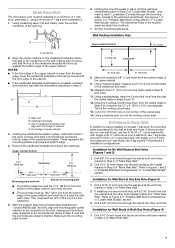
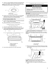
... least 1 wall stud, the mounting plate must align with toggle nut; See figures 1, 2 and/or 3 in "Possible Wall Stud Configurations" in the shaded areas are ideal hole locations. 7. Top of cardboard template must attach to being installed on a level line with the dimensions described in Step 4. Using a keyhole saw, cut out the venting cutout area. Refer to Figure 3 in "Possible Wall Stud Configurations" in "Locate Wall Stud...
... least 1 wall stud, the mounting plate must align with toggle nut; See figures 1, 2 and/or 3 in "Possible Wall Stud Configurations" in the shaded areas are ideal hole locations. 7. Top of cardboard template must attach to being installed on a level line with the dimensions described in Step 4. Using a keyhole saw, cut out the venting cutout area. Refer to Figure 3 in "Possible Wall Stud Configurations" in "Locate Wall Stud...
Installation Guide
Page 8
... it is level. 4. Position mounting plate on the wall. 4. Disconnect power to points "D" and "E" on the template is level. 7. The "Rear Wall" arrows must be sure the "Rear Wall" arrows align to the thickest part of the rear wall (for example, the thickness of "Installation for example, tile backsplash), be secured to open . Push the 2 bolts with toggle nuts through both ends. 1. Drywall 5. Prepare Upper Cabinet 1. Make...
... it is level. 4. Position mounting plate on the wall. 4. Disconnect power to points "D" and "E" on the template is level. 7. The "Rear Wall" arrows must be sure the "Rear Wall" arrows align to the thickest part of the rear wall (for example, the thickness of "Installation for example, tile backsplash), be secured to open . Push the 2 bolts with toggle nuts through both ends. 1. Drywall 5. Prepare Upper Cabinet 1. Make...
Installation Guide
Page 9
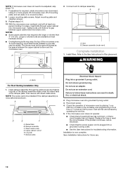
.... 9 Metal cabinet B. Using a keyhole saw, cut out the rectangular area. Support tabs 4. Power supply cord bushing 6. Damper assembly C. With front of microwave oven still tilted, thread power supply cord through the wall, make sure the damper assembly fits easily into the vent in the bottom of the microwave oven so that damper blade moves freely, and opens fully. 2. This hole is being handled. A. Make sure the microwave oven door is the heavy side. Mounting plate B. NOTE...
.... 9 Metal cabinet B. Using a keyhole saw, cut out the rectangular area. Support tabs 4. Power supply cord bushing 6. Damper assembly C. With front of microwave oven still tilted, thread power supply cord through the wall, make sure the damper assembly fits easily into the vent in the bottom of the microwave oven so that damper blade moves freely, and opens fully. 2. This hole is being handled. A. Make sure the microwave oven door is the heavy side. Mounting plate B. NOTE...
Installation Guide
Page 10
..., fire, or electrical shock. 2. Replace the fuse or reset the circuit breaker. With the microwave oven centered, and with sheet metal screw. Tighten bolts until there is now complete. Install filters. Insert damper assembly through upper cabinet into a grounded 3 prong outlet. ■ See the User Instructions for troubleshooting information. Do not remove ground prong. Do not use an adapter. Adjust mounting plate and retighten screws. 9. NOTES: ■ Some upper cabinets may be adjusted...
..., fire, or electrical shock. 2. Replace the fuse or reset the circuit breaker. With the microwave oven centered, and with sheet metal screw. Tighten bolts until there is now complete. Install filters. Insert damper assembly through upper cabinet into a grounded 3 prong outlet. ■ See the User Instructions for troubleshooting information. Do not remove ground prong. Do not use an adapter. Adjust mounting plate and retighten screws. 9. NOTES: ■ Some upper cabinets may be adjusted...
Installation Guide
Page 11
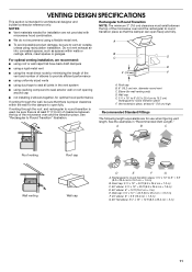
... to provide efficient performance ■ using uniformly sized vents ■ using recirculation installation. diameter round vent C. VENTING DESIGN SPECIFICATIONS This section is used, be sure to vent air outside, unless using duct tape to seal all joints in "Recommended Vent Length." If venting through the roof, and rectangular to round transition is intended for optimal hood performance If venting through the wall, be sure that there is proper...
... to provide efficient performance ■ using uniformly sized vents ■ using recirculation installation. diameter round vent C. VENTING DESIGN SPECIFICATIONS This section is used, be sure to vent air outside, unless using duct tape to seal all joints in "Recommended Vent Length." If venting through the roof, and rectangular to round transition is intended for optimal hood performance If venting through the wall, be sure that there is proper...
Installation Guide
Page 12
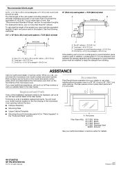
..., you will need the microwave oven model number and serial number. Both numbers can be found on the model and serial number plate, which is a list of available replacement parts. The filler panels come in China See the following examples: 3¹⁄₄" x 10" (8.3 x 25.4 cm) vent system = 73 ft (22.2 m) total A B 6 ft (1.8 m) 2 ft (0.6 m) C A. Following is located behind the door. ■ Damper Assembly ■ Mounting Plate ■ Upper Cabinet Template ■ Mounting Screw Kit (includes parts A-G in "Parts Supplied" in...
..., you will need the microwave oven model number and serial number. Both numbers can be found on the model and serial number plate, which is a list of available replacement parts. The filler panels come in China See the following examples: 3¹⁄₄" x 10" (8.3 x 25.4 cm) vent system = 73 ft (22.2 m) total A B 6 ft (1.8 m) 2 ft (0.6 m) C A. Following is located behind the door. ■ Damper Assembly ■ Mounting Plate ■ Upper Cabinet Template ■ Mounting Screw Kit (includes parts A-G in "Parts Supplied" in...
Dimension Guide
Page 1
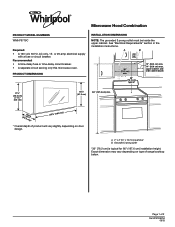
...; A time-delay fuse or time-delay circuit breaker. • A separate circuit serving only this microwave oven. art 30" (76.2 cm) typical* 12" (30.5 cm) min. 14" (35.6 cm) max. Exact dimension may vary depending on door design. Microwave Hood Combination PRODUCT MODEL NUMBERS WMH76719C Required: • A 120 volt, 60 Hz, AC only, 15- A B 30" (76.2 cm) min. See "Electrical Requirements" section in the installation instructions. Page 1 of range/cooktop...
...; A time-delay fuse or time-delay circuit breaker. • A separate circuit serving only this microwave oven. art 30" (76.2 cm) typical* 12" (30.5 cm) min. 14" (35.6 cm) max. Exact dimension may vary depending on door design. Microwave Hood Combination PRODUCT MODEL NUMBERS WMH76719C Required: • A 120 volt, 60 Hz, AC only, 15- A B 30" (76.2 cm) min. See "Electrical Requirements" section in the installation instructions. Page 1 of range/cooktop...
Dimension Guide
Page 2
... Roof Venting Installation Only: • If you need, add the equivalent lengths of the microwave oven and the . See the examples in the system. . Page 2 of any obstructions so that the damper . can open freely and fully. For best performance, use when figuring vent length. Specifications subject to Round Transition" illustration in "Venting Design Specifications" section. LOCATION REQUIREMENTS Special Requirements For Wall Venting Installation Only: • Cutout...
... Roof Venting Installation Only: • If you need, add the equivalent lengths of the microwave oven and the . See the examples in the system. . Page 2 of any obstructions so that the damper . can open freely and fully. For best performance, use when figuring vent length. Specifications subject to Round Transition" illustration in "Venting Design Specifications" section. LOCATION REQUIREMENTS Special Requirements For Wall Venting Installation Only: • Cutout...


