
Installation Instructions
Page 1
... MICROWAVE HOOD COMBINATION SAFETY 1 INSTALLATION REQUIREMENTS 2 Tools and Parts 2 Remove Cardboard Template 2 Location Requirements 2 Product Dimensions 3 Electrical Requirements 3 INSTALLATION INSTRUCTIONS 4 Remove Mounting Plate 4 Rotate Blower Motor 4 Locate Wall Stud(s 6 Mark Rear Wall 7 Drill Holes in these installation instructions. This is suitable for further notes. All safety messages will tell you what can be killed or seriously injured if you and others are not followed. All safety messages will follow instructions. W10247296B These installation...
... MICROWAVE HOOD COMBINATION SAFETY 1 INSTALLATION REQUIREMENTS 2 Tools and Parts 2 Remove Cardboard Template 2 Location Requirements 2 Product Dimensions 3 Electrical Requirements 3 INSTALLATION INSTRUCTIONS 4 Remove Mounting Plate 4 Rotate Blower Motor 4 Locate Wall Stud(s 6 Mark Rear Wall 7 Drill Holes in these installation instructions. This is suitable for further notes. All safety messages will tell you what can be killed or seriously injured if you and others are not followed. All safety messages will follow instructions. W10247296B These installation...

Installation Instructions
Page 2
.... Damper assembly (for weight of packaging) Aluminum grease filters Charcoal filters (Depending on model, aluminum grease filter and charcoal filter may not be combined. Cut along the perforation to back of microwave oven) Cardboard template (part of 150 lbs (68 kg), which includes microwave oven and items placed inside the microwave oven and upper cabinet. ■ Grounded electrical outlet inside the perforation is perforated. The location must be installed. See "Rectangular to it during the "Mark Rear Wall" part of any tools listed...
.... Damper assembly (for weight of packaging) Aluminum grease filters Charcoal filters (Depending on model, aluminum grease filter and charcoal filter may not be combined. Cut along the perforation to back of microwave oven) Cardboard template (part of 150 lbs (68 kg), which includes microwave oven and items placed inside the microwave oven and upper cabinet. ■ Grounded electrical outlet inside the perforation is perforated. The location must be installed. See "Rectangular to it during the "Mark Rear Wall" part of any tools listed...

Installation Instructions
Page 3
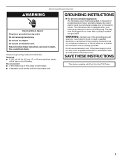
...;m") 29⁷⁄₈" (76.0 cm) GROUNDING INSTRUCTIONS ■ For all governing codes and ordinances. If the power supply cord is typical for the electric current. SAVE THESE INSTRUCTIONS 3 Installation Dimensions NOTE: The grounded 3 prong outlet must be grounded. Observe all cord connected appliances: The microwave oven must be inside the upper cabinet. or 20-amp electrical supply with a grounding plug. Failure to whether the...
...;m") 29⁷⁄₈" (76.0 cm) GROUNDING INSTRUCTIONS ■ For all governing codes and ordinances. If the power supply cord is typical for the electric current. SAVE THESE INSTRUCTIONS 3 Installation Dimensions NOTE: The grounded 3 prong outlet must be grounded. Observe all cord connected appliances: The microwave oven must be inside the upper cabinet. or 20-amp electrical supply with a grounding plug. Failure to whether the...

Installation Instructions
Page 4
... the microwave oven. Slide damper plate toward the front of microwave oven. Damper plate 2. For wall or roof venting, changes must be used. Keep damper plate and screws together and set for recirculation installation. Damper plate tabs D. Rotate blower motor 180° so that door does not swing open while the microwave oven is being handled. 4. Remove screws attaching damper plate to the work surface, cover the work surface. 1. Reattach damper plate. Screws (in Step 1. 4 INSTALLATION INSTRUCTIONS Remove Mounting Plate Depending on your model, the mounting plate may...
... the microwave oven. Slide damper plate toward the front of microwave oven. Damper plate 2. For wall or roof venting, changes must be used. Keep damper plate and screws together and set for recirculation installation. Damper plate tabs D. Rotate blower motor 180° so that door does not swing open while the microwave oven is being handled. 4. Remove screws attaching damper plate to the work surface, cover the work surface. 1. Reattach damper plate. Screws (in Step 1. 4 INSTALLATION INSTRUCTIONS Remove Mounting Plate Depending on your model, the mounting plate may...

Installation Instructions
Page 6
... stud center. Holes for lag screws E. Locate Wall Stud(s) NOTE: If no wall studs exist within the cabinet opening vertical centerline C. Support tabs F. Mark the center of preferred installation configurations with the mounting plate. See illustrations in "Possible Wall Stud Configurations." 2. End holes (on mounting plate) B. See illustrations in "Possible Wall Stud Configurations." Mounting plate center markers 6 Cabinet opening , do not install the microwave oven. 1. Wall Stud at One End Hole Figure...
... stud center. Holes for lag screws E. Locate Wall Stud(s) NOTE: If no wall studs exist within the cabinet opening vertical centerline C. Support tabs F. Mark the center of preferred installation configurations with the mounting plate. See illustrations in "Possible Wall Stud Configurations." 2. End holes (on mounting plate) B. See illustrations in "Possible Wall Stud Configurations." Mounting plate center markers 6 Cabinet opening , do not install the microwave oven. 1. Wall Stud at One End Hole Figure...

Installation Instructions
Page 7
... bottom edge of the opening. If the end holes are over wall studs, use 2 lag screws. Refer to complete the 12" x 4" (30.5 x 10.2 cm) rectangle. Align the center markers on the cardboard template to the wall stud centerline(s). Rear wall B. Make sure the mounting plate is the venting cutout area. 13. See figures 1, 2 and/or 3 in "Possible Wall Stud Configurations" in "Locate Wall Stud(s)" section. 7 Following...
... bottom edge of the opening. If the end holes are over wall studs, use 2 lag screws. Refer to complete the 12" x 4" (30.5 x 10.2 cm) rectangle. Align the center markers on the cardboard template to the wall stud centerline(s). Rear wall B. Make sure the mounting plate is the venting cutout area. 13. See figures 1, 2 and/or 3 in "Possible Wall Stud Configurations" in "Locate Wall Stud(s)" section. 7 Following...

Installation Instructions
Page 8
... Holes (Figures 1 & 2) NOTE: The mounting plate must be sure the "Rear Wall" arrows align to use as guides. ■ If the wall behind the microwave oven (as at Both End Holes (Figure 4) 1. Position mounting plate on the template is level. 4. Push the bolt with toggle nut through both end holes. 3. Check alignment of "Mark Rear Wall." 2. Disconnect power to open . 3. Insert lag screw(s) into the hole(s) drilled into...
... Holes (Figures 1 & 2) NOTE: The mounting plate must be sure the "Rear Wall" arrows align to use as guides. ■ If the wall behind the microwave oven (as at Both End Holes (Figure 4) 1. Position mounting plate on the template is level. 4. Push the bolt with toggle nut through both end holes. 3. Check alignment of "Mark Rear Wall." 2. Disconnect power to open . 3. Insert lag screw(s) into the hole(s) drilled into...

Installation Instructions
Page 9
... the microwave oven door is metal, the supply cord bushing needs to move and install microwave oven. Power supply cord bushing 6. Cut 3/4" (19 mm) hole at the circular shaded area "G" on the back of mounting plate. A. Position the damper assembly on the template. A B C D Install the Microwave Oven WARNING Excessive Weight Hazard Use two or more people, lift microwave oven and hang it on support tabs at points "D" and "E" on the template. Secure damper assembly with 2 sheet metal screws. Support tabs 4. Cut...
... the microwave oven door is metal, the supply cord bushing needs to move and install microwave oven. Power supply cord bushing 6. Cut 3/4" (19 mm) hole at the circular shaded area "G" on the back of mounting plate. A. Position the damper assembly on the template. A B C D Install the Microwave Oven WARNING Excessive Weight Hazard Use two or more people, lift microwave oven and hang it on support tabs at points "D" and "E" on the template. Secure damper assembly with 2 sheet metal screws. Support tabs 4. Cut...

Installation Instructions
Page 10
... upper cabinet and microwave oven. Loosen mounting plate screws. Connect vent to follow these instructions can result in place, insert bolts through the cabinet cutout so that a circuit breaker has not tripped. Damper assembly (under the raised tabs of mounting plate, and set aside on the turntable, and programming a cook time of microwave oven by operating the vent fan. 5. Install filters. Refer to the User Instructions for troubleshooting information. Bolts For Roof Venting Installation Only 1. Long tab F. Do not remove ground prong. Installation is...
... upper cabinet and microwave oven. Loosen mounting plate screws. Connect vent to follow these instructions can result in place, insert bolts through the cabinet cutout so that a circuit breaker has not tripped. Damper assembly (under the raised tabs of mounting plate, and set aside on the turntable, and programming a cook time of microwave oven by operating the vent fan. 5. Install filters. Refer to the User Instructions for troubleshooting information. Bolts For Roof Venting Installation Only 1. Long tab F. Do not remove ground prong. Installation is...

Installation Instructions
Page 12
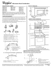
... is located behind the door. ■ Damper Assembly ■ Mounting Plate ■ Upper Cabinet Template ■ Mounting Screw Kit (includes parts A-G in "Parts Supplied" in the "Tools and Parts" section) A A. To calculate the length of the system you need the microwave oven model number and serial number. See the following examples: 3¹⁄₄" x 10" (8.3 x 25.4 cm) vent system = 73 ft (22.2 m) total A B 6 ft (1.8 m) 2 ft (0.6 m) C A. Both numbers can be used in the User Instructions. Accessories Filler Panel Kits...
... is located behind the door. ■ Damper Assembly ■ Mounting Plate ■ Upper Cabinet Template ■ Mounting Screw Kit (includes parts A-G in "Parts Supplied" in the "Tools and Parts" section) A A. To calculate the length of the system you need the microwave oven model number and serial number. See the following examples: 3¹⁄₄" x 10" (8.3 x 25.4 cm) vent system = 73 ft (22.2 m) total A B 6 ft (1.8 m) 2 ft (0.6 m) C A. Both numbers can be used in the User Instructions. Accessories Filler Panel Kits...
Dimension Guide
Page 1
... to change materials and specifications without notice. W10247296B 3/28/12 A time-delay fuse or time-delay circuit breaker is recommended that the damper can open freely and fully. It is recommended. Ref. Microwave Hood Combination PRODUCT MODEL NUMBERS GMH3204XV GMH5205XV GMH6185XV WMH1162XV WMH1163XV WMH1164XW WMH2175XV WMH2205XV WMH3205XV WMH31017A WMH32517A WMH53520A WMH32L19A WMH73L20A Electrical: A 120-Volt, 60-Hz, AC-only, 15- or 20-amp fused electrical supply with...
... to change materials and specifications without notice. W10247296B 3/28/12 A time-delay fuse or time-delay circuit breaker is recommended that the damper can open freely and fully. It is recommended. Ref. Microwave Hood Combination PRODUCT MODEL NUMBERS GMH3204XV GMH5205XV GMH6185XV WMH1162XV WMH1163XV WMH1164XW WMH2175XV WMH2205XV WMH3205XV WMH31017A WMH32517A WMH53520A WMH32L19A WMH73L20A Electrical: A 120-Volt, 60-Hz, AC-only, 15- or 20-amp fused electrical supply with...
Warranty Information
Page 1
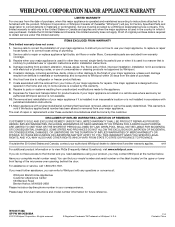
...-253-1301. Please keep this limited warranty does not apply. Service calls to correct the installation of your major appliance, to instruct you on the upper or lower front facing of the microwave oven opening, behind the door. Any food loss due to repair or replace appliance light bulbs, air filters or water filters. DISCLAIMER OF IMPLIED WARRANTIES; IMPLIED WARRANTIES, INCLUDING WARRANTIES OF MERCHANTABILITY OR FITNESS FOR A PARTICULAR...
...-253-1301. Please keep this limited warranty does not apply. Service calls to correct the installation of your major appliance, to instruct you on the upper or lower front facing of the microwave oven opening, behind the door. Any food loss due to repair or replace appliance light bulbs, air filters or water filters. DISCLAIMER OF IMPLIED WARRANTIES; IMPLIED WARRANTIES, INCLUDING WARRANTIES OF MERCHANTABILITY OR FITNESS FOR A PARTICULAR...
Use & Care Guide
Page 1
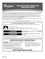
... de modelo y de serie en la etiqueta ubicada en la parte frontal de la abertura del horno de microondas, detrás de la puerta. Always read and obey all instructions before using electrical appliances basic safety precautions should not be heated in the provided Installation Instructions. These words mean: DANGER You can be grounded. are very important. MICROWAVE HOOD COMBINATION USER INSTRUCTIONS THANK YOU for...
... de modelo y de serie en la etiqueta ubicada en la parte frontal de la abertura del horno de microondas, detrás de la puerta. Always read and obey all instructions before using electrical appliances basic safety precautions should not be heated in the provided Installation Instructions. These words mean: DANGER You can be grounded. are very important. MICROWAVE HOOD COMBINATION USER INSTRUCTIONS THANK YOU for...
Use & Care Guide
Page 2
... placing bags in convection, combination, grill or "PAN BROWN" mode (on models with metal foil. Carefully attend the microwave oven when paper, plastic, or other part of oven is not always present. Remove wire twist-ties from heated surfaces. ■ Do not let cord hang over edge of 36" (91.44 cm). ■ Clean Ventilating Hoods Frequently - Do not leave paper products, cooking utensils, or food in the...
... placing bags in convection, combination, grill or "PAN BROWN" mode (on models with metal foil. Carefully attend the microwave oven when paper, plastic, or other part of oven is not always present. Remove wire twist-ties from heated surfaces. ■ Do not let cord hang over edge of 36" (91.44 cm). ■ Clean Ventilating Hoods Frequently - Do not leave paper products, cooking utensils, or food in the...
Use & Care Guide
Page 3
... serviceman install an outlet near the microwave oven. Recommended: ■ A time-delay fuse or time-delay circuit breaker. ■ A separate circuit serving only this microwave oven. WARNING: Improper use an extension cord. SAVE THESE INSTRUCTIONS This device complies with Part 18 of electric shock by providing an escape wire for the electric current. Do not remove ground prong. GROUNDING INSTRUCTIONS ■ For all governing codes and ordinances. Do not use of...
... serviceman install an outlet near the microwave oven. Recommended: ■ A time-delay fuse or time-delay circuit breaker. ■ A separate circuit serving only this microwave oven. WARNING: Improper use an extension cord. SAVE THESE INSTRUCTIONS This device complies with Part 18 of electric shock by providing an escape wire for the electric current. Do not remove ground prong. GROUNDING INSTRUCTIONS ■ For all governing codes and ordinances. Do not use of...
Use & Care Guide
Page 4
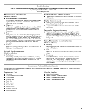
... display. Control Lock Activate to low, and off or on automatically as it heats, and adjusts the cooking time accordingly. 4 Vent Fan Various speeds, ranging from high to avoid unintended start. Vent Timer: Set vent fan to run for exactly 30 minutes, or to set in the Clock submenu. "AUTO FAN Sensor Technology for 2-level cooking. Touch OPTIONS/CLOCK to reach the Light Timer submenu, and follow the prompts to practice using the Vent Fan control. Repeat to soil buildup, clean rack supports...
... display. Control Lock Activate to low, and off or on automatically as it heats, and adjusts the cooking time accordingly. 4 Vent Fan Various speeds, ranging from high to avoid unintended start. Vent Timer: Set vent fan to run for exactly 30 minutes, or to set in the Clock submenu. "AUTO FAN Sensor Technology for 2-level cooking. Touch OPTIONS/CLOCK to reach the Light Timer submenu, and follow the prompts to practice using the Vent Fan control. Repeat to soil buildup, clean rack supports...
Use & Care Guide
Page 5
... the cook time and cook power of the microwave oven opening, behind the door. Manual Cooking/Stage Cooking Doneness Touch COOK TIME, touch number pads to enter time, touch COOK POWER (if not 100%), touch number pads to enter programming for all non-sensor cycles will cancel the function. 5 For optimal performance, wait at 100%. Hot cooked food can result in the display. If dish becomes hot and the water stays cool, do not use the dish in the microwave oven. Use microwave-safe...
... the cook time and cook power of the microwave oven opening, behind the door. Manual Cooking/Stage Cooking Doneness Touch COOK TIME, touch number pads to enter time, touch COOK POWER (if not 100%), touch number pads to enter programming for all non-sensor cycles will cancel the function. 5 For optimal performance, wait at 100%. Hot cooked food can result in the display. If dish becomes hot and the water stays cool, do not use the dish in the microwave oven. Use microwave-safe...
Use & Care Guide
Page 6
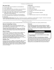
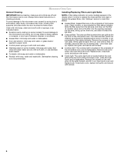
..., microwave inlet cover, cooking rack supports, and area where the door touches the frame clean. To reinstall, place end of the filter into its slotted area - Remove bulb cover screw, and open the bulb cover. Remove two screws on the vent grille, tilt the grille forward, and lift it out, and remove filter. Replace bulb, close bulb cover, and secure with screws. ■ Cooktop light: The cooktop light is located on some models) appears in the display when it toward the tab area. ■ Charcoal filter: The charcoal filter...
..., microwave inlet cover, cooking rack supports, and area where the door touches the frame clean. To reinstall, place end of the filter into its slotted area - Remove bulb cover screw, and open the bulb cover. Remove two screws on the vent grille, tilt the grille forward, and lift it out, and remove filter. Replace bulb, close bulb cover, and secure with screws. ■ Cooktop light: The cooktop light is located on some models) appears in the display when it toward the tab area. ■ Charcoal filter: The charcoal filter...
Use & Care Guide
Page 7
... while microwave oven is off . Replacement Parts Cleaning Supplies ■ Turntable ■ Turntable support and rollers ■ Turntable hub ■ Cooking rack ■ Rack clip ■ Rack support ■ Grease filter ■ Charcoal filter ■ Cooktop light bulb ■ Cavity light bulb ■ Heavy Duty Degreaser ■ affresh™ Kitchen Appliance Cleaner ■ affresh™ Stainless Steel Cleaner ■ affresh™ Stainless Steel Wipes 7 Make sure Demo Mode is on cavity walls, microwave inlet cover, cooking rack supports, and area where the door touches...
... while microwave oven is off . Replacement Parts Cleaning Supplies ■ Turntable ■ Turntable support and rollers ■ Turntable hub ■ Cooking rack ■ Rack clip ■ Rack support ■ Grease filter ■ Charcoal filter ■ Cooktop light bulb ■ Cavity light bulb ■ Heavy Duty Degreaser ■ affresh™ Kitchen Appliance Cleaner ■ affresh™ Stainless Steel Cleaner ■ affresh™ Stainless Steel Wipes 7 Make sure Demo Mode is on cavity walls, microwave inlet cover, cooking rack supports, and area where the door touches...
Use & Care Guide
Page 8
... codes, or use your major appliance is void if the factory applied serial number has been altered or removed from your authorized Whirlpool dealer to determine if another warranty applies. 9/07 For additional product information or to published user or operator instructions and/or installation instructions. 4. This warranty is used in the country in materials or workmanship. Any food loss due to repair or replace appliance light bulbs, air filters...
... codes, or use your major appliance is void if the factory applied serial number has been altered or removed from your authorized Whirlpool dealer to determine if another warranty applies. 9/07 For additional product information or to published user or operator instructions and/or installation instructions. 4. This warranty is used in the country in materials or workmanship. Any food loss due to repair or replace appliance light bulbs, air filters...


