Installation Guide
Page 1
These installation instructions cover different models. Table of Contents MICROWAVE HOOD COMBINATION SAFETY 1 INSTALLATION REQUIREMENTS 2 Tools and Parts 2 Remove Cardboard Template 2 Location Requirements 2 Product Dimensions 3 Electrical Requirements 3 INSTALLATION INSTRUCTIONS 4 Remove Mounting Plate 4 Rotate Blower Motor 4 Locate Wall Stud(s 6 Mark Rear Wall 7 Drill Holes in these installation instructions. Always read and ...
These installation instructions cover different models. Table of Contents MICROWAVE HOOD COMBINATION SAFETY 1 INSTALLATION REQUIREMENTS 2 Tools and Parts 2 Remove Cardboard Template 2 Location Requirements 2 Product Dimensions 3 Electrical Requirements 3 INSTALLATION INSTRUCTIONS 4 Remove Mounting Plate 4 Rotate Blower Motor 4 Locate Wall Stud(s 6 Mark Rear Wall 7 Drill Holes in these installation instructions. Always read and ...
Installation Guide
Page 2
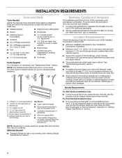
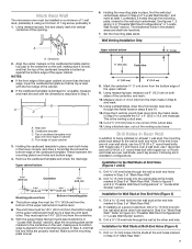
...bolts (2) C. Z\v" x 2" lag screws (2) F. The piece inside upper cabinet. The location must be sure to Round Transition" illustration in "Venting Design Specifications" section. 2 See "Installation Dimensions" illustration. ■■ Minimum one 2" x 4" (50.8 x 101.6 mm) wood wall stud and minimum C\," (10 mm) thickness drywall or plaster/lath within cabinet opening where ...NOTE: Depending on reordering, see "Replacement Parts" section. Special Requirements For Wall Venting Installation Only: ■■ Cutout must provide: ■■ Minimum installation dimensions.
...bolts (2) C. Z\v" x 2" lag screws (2) F. The piece inside upper cabinet. The location must be sure to Round Transition" illustration in "Venting Design Specifications" section. 2 See "Installation Dimensions" illustration. ■■ Minimum one 2" x 4" (50.8 x 101.6 mm) wood wall stud and minimum C\," (10 mm) thickness drywall or plaster/lath within cabinet opening where ...NOTE: Depending on reordering, see "Replacement Parts" section. Special Requirements For Wall Venting Installation Only: ■■ Cutout must provide: ■■ Minimum installation dimensions.
Installation Guide
Page 3
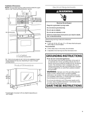
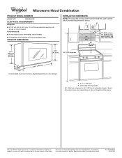
... an extension cord. Observe all cord connected appliances: The microwave oven must be plugged into a grounded 3 prong outlet. Exact dimensions may vary depending on door design. If the power supply cord is properly grounded. Recommended: ■■ A time-delay fuse...(30.5 cm) min. 14" (35.6 cm) max. GROUNDING INSTRUCTIONS I For all governing codes and ordinances. A. 2" x 4" wall stud B. Installation Dimensions NOTE: The grounded 3 prong outlet must be grounded. Do not use of product will vary slightly depending on type of electric shock by providing an...
... an extension cord. Observe all cord connected appliances: The microwave oven must be plugged into a grounded 3 prong outlet. Exact dimensions may vary depending on door design. If the power supply cord is properly grounded. Recommended: ■■ A time-delay fuse...(30.5 cm) min. 14" (35.6 cm) max. GROUNDING INSTRUCTIONS I For all governing codes and ordinances. A. 2" x 4" wall stud B. Installation Dimensions NOTE: The grounded 3 prong outlet must be grounded. Do not use of product will vary slightly depending on type of electric shock by providing an...
Installation Guide
Page 7
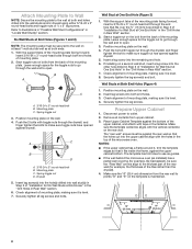
... cardboard template in place, mark both holes in Step 3 of "Mark Rear Wall." Using measuring tape, measure out 6" (15.2 cm) on a level line with the dimensions described in steps 8 and 10. 12. Using a keyhole saw, cut out the venting cutout area. If the end holes are over wall studs, use two...
... cardboard template in place, mark both holes in Step 3 of "Mark Rear Wall." Using measuring tape, measure out 6" (15.2 cm) on a level line with the dimensions described in steps 8 and 10. 12. Using a keyhole saw, cut out the venting cutout area. If the end holes are over wall studs, use two...
Installation Guide
Page 8
... installed) has a partial wall covering (for the toggle nuts to go through both end holes drilled into both ends. 1. Make sure the 10" (25.4 cm) dimension from the back of the mounting plate. Start toggle nuts on bolts from the rear wall to the wall on the rear wall. Start a toggle...
... installed) has a partial wall covering (for the toggle nuts to go through both end holes drilled into both ends. 1. Make sure the 10" (25.4 cm) dimension from the back of the mounting plate. Start toggle nuts on bolts from the rear wall to the wall on the rear wall. Start a toggle...
Dimension Guide
Page 1
...167.6 cm) installation height. PRODUCT DIMENSIONS INSTALLATION DIMENSIONS NOTE: The grounded 3 prong outlet must be inside the upper cabinet. Grounded 3 prong outlet * 30" (76.2 cm) is typical for planning purposes only. W10823831A 06/30/2016 Because Whirlpool Corporation includes a continuous commitment to .... A B 30" (76.2 cm) min. 30" (76.2 cm) typical* 12" (30.5 cm) min. 14" (35.6 cm) max. Exact dimensions may vary depending on door design. For complete details, see Installation Instructions packed with a fuse or circuit breaker. A. 2" x 4" wall stud B. Ref. Microwave...
...167.6 cm) installation height. PRODUCT DIMENSIONS INSTALLATION DIMENSIONS NOTE: The grounded 3 prong outlet must be inside the upper cabinet. Grounded 3 prong outlet * 30" (76.2 cm) is typical for planning purposes only. W10823831A 06/30/2016 Because Whirlpool Corporation includes a continuous commitment to .... A B 30" (76.2 cm) min. 30" (76.2 cm) typical* 12" (30.5 cm) min. 14" (35.6 cm) max. Exact dimensions may vary depending on door design. For complete details, see Installation Instructions packed with a fuse or circuit breaker. A. 2" x 4" wall stud B. Ref. Microwave...


