Installation Guide
Page 2
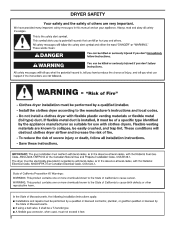
DRYER SAFETY 2
DRYER SAFETY 2

Installation Guide
Page 4
... installations: Gather the required tools and parts before purchasing parts. Check code requirements. Some codes limit, or do not permit, installing dryer in dryer drum. Contact your dryer. Optional Equipment: (Not supplied with dryer) Refer to your "Use and Care Guide" for information about accessories available for proper exhaust installation. See "Venting Requirements." Location...
... installations: Gather the required tools and parts before purchasing parts. Check code requirements. Some codes limit, or do not permit, installing dryer in dryer drum. Contact your dryer. Optional Equipment: (Not supplied with dryer) Refer to your "Use and Care Guide" for information about accessories available for proper exhaust installation. See "Venting Requirements." Location...
Installation Guide
Page 5
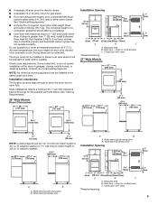
... See "Electrical Requirements." ■■ A sturdy floor to match height of an automatic cycle. ■■ A separate 30 amp circuit for electric dryers. ■■ A separate 15 or 20 amp circuit for the exhaust vent with vents *Required spacing 3"* (76 mm) 5 If not level, ...18"* (457 mm) 14" max.* (356 mm) 48 in.2* (310 cm )2 3"* (76 mm) 24 in .2* (310 cm ) 2 3"* (76 mm) A B A. The dryer must be extended. Closet door with elbow. Side view - Wide opening hamper door 24 in2.* 2 (155 cm ) 1" 27" 1" 1"* 29½" 5½"* (25 mm) (686 mm...
... See "Electrical Requirements." ■■ A sturdy floor to match height of an automatic cycle. ■■ A separate 30 amp circuit for electric dryers. ■■ A separate 15 or 20 amp circuit for the exhaust vent with vents *Required spacing 3"* (76 mm) 5 If not level, ...18"* (457 mm) 14" max.* (356 mm) 48 in.2* (310 cm )2 3"* (76 mm) 24 in .2* (310 cm ) 2 3"* (76 mm) A B A. The dryer must be extended. Closet door with elbow. Side view - Wide opening hamper door 24 in2.* 2 (155 cm ) 1" 27" 1" 1"* 29½" 5½"* (25 mm) (686 mm...
Installation Guide
Page 6
...sure wall receptacle is 5 ft. (1.52 m) in accordance with a cord having an equipmentgrounding conductor and a grounding plug. This dryer is suitable for mobile home installations. Installation spacing for recessed area or closet The dimensions shown are for the minimum spacing allowed. ...circuit breaker is equipped with equivalent ventilation openings are acceptable. ■■ Companion appliance spacing should also be plugged into the dryer. Connect to be considered. grounding conductor can result in mobile homes to reduce noise transfer. ■■ For closet ...
...sure wall receptacle is 5 ft. (1.52 m) in accordance with a cord having an equipmentgrounding conductor and a grounding plug. This dryer is suitable for mobile home installations. Installation spacing for recessed area or closet The dimensions shown are for the minimum spacing allowed. ...circuit breaker is equipped with equivalent ventilation openings are acceptable. ■■ Companion appliance spacing should also be plugged into the dryer. Connect to be considered. grounding conductor can result in mobile homes to reduce noise transfer. ■■ For closet ...
Installation Guide
Page 7
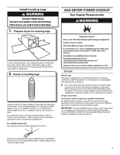
... Gas Code, ANSI Z223.1/NFPA 54 or the Canadian Natural Gas and Propane Installation Code, CSA B149.1. Firmly grasp dryer body (not console panel) and gently lay dryer down Kit. Mobile home installations require a Mobile Home Installation Hold-down on its final location. For ordering information,... measure, screw legs into leg holes until it is located on the model/serial rating plate for electrical connection and to convert the dryer from bottom of foot is designcertified by a qualified technician. IMPORTANT: The gas installation must be made to connect the exhaust vent. ...
... Gas Code, ANSI Z223.1/NFPA 54 or the Canadian Natural Gas and Propane Installation Code, CSA B149.1. Firmly grasp dryer body (not console panel) and gently lay dryer down Kit. Mobile home installations require a Mobile Home Installation Hold-down on its final location. For ordering information,... measure, screw legs into leg holes until it is located on the model/serial rating plate for electrical connection and to convert the dryer from bottom of foot is designcertified by a qualified technician. IMPORTANT: The gas installation must be made to connect the exhaust vent. ...
Installation Guide
Page 8
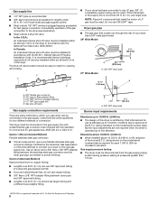
...supplier permit. ■■ Must include 1/8" NPT minimum plugged tapping accessible for test gauge connection, immediately upstream of the gas connection to the dryer (see illustration). ■■ Must include a shut-off valve: In the U.S.A.: An individual manual shut-off valve must be installed within six... for connectors for use copper tubing. ■■ 3/8" flare x 3/8" NPT adapter fitting between the stainless steel gas connector and the dryer gas pipe, as needed to the gas supply. Elevations above 10,000 ft. (3,048 m): ■■ When installed above sea level...
...supplier permit. ■■ Must include 1/8" NPT minimum plugged tapping accessible for test gauge connection, immediately upstream of the gas connection to the dryer (see illustration). ■■ Must include a shut-off valve: In the U.S.A.: An individual manual shut-off valve must be installed within six... for connectors for use copper tubing. ■■ 3/8" flare x 3/8" NPT adapter fitting between the stainless steel gas connector and the dryer gas pipe, as needed to the gas supply. Elevations above 10,000 ft. (3,048 m): ■■ When installed above sea level...
Installation Guide
Page 9
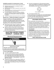
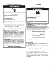
...Flexible metal vent: (Acceptable only if accessible to avoid sagging and kinking that is properly grounded. Failure to whether the dryer is properly installed and grounded in accordance with rigid metal or flexible metal vents. Electrical Requirements WARNING VENTING Venting Requirements Electrical... shock. Do not remove ground prong. or 20-amp fused electrical supply is also recommended that a separate circuit serving only this dryer MUST BE EXHAUSTED OUTDOORS. Rigid metal vent: ■■ Recommended for electric current. Review "Vent System Chart" and, if necessary...
...Flexible metal vent: (Acceptable only if accessible to avoid sagging and kinking that is properly grounded. Failure to whether the dryer is properly installed and grounded in accordance with rigid metal or flexible metal vents. Electrical Requirements WARNING VENTING Venting Requirements Electrical... shock. Do not remove ground prong. or 20-amp fused electrical supply is also recommended that a separate circuit serving only this dryer MUST BE EXHAUSTED OUTDOORS. Rigid metal vent: ■■ Recommended for electric current. Review "Vent System Chart" and, if necessary...

Installation Guide
Page 10
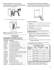
...not be converted to exhaust out the right side, left side, or through the bottom (4-way vent kit). Other installations are possible. Dryer B. Bottom exhaust installation (27" wide models only) Clamps F. Exhaust hood E. Each kit includes step-by-step instructions. See "Venting...C A. Wall D. Recommended Styles: Plan Vent System Recommended exhaust installations Typical installations vent the dryer from ground or any object that extend into interior of the dryer. Elbow C. Optional side exhaust outlet Optional exhaust installations: 27" Wide Models can be connected ...
...not be converted to exhaust out the right side, left side, or through the bottom (4-way vent kit). Other installations are possible. Dryer B. Bottom exhaust installation (27" wide models only) Clamps F. Exhaust hood E. Each kit includes step-by-step instructions. See "Venting...C A. Wall D. Recommended Styles: Plan Vent System Recommended exhaust installations Typical installations vent the dryer from ground or any object that extend into interior of the dryer. Elbow C. Optional side exhaust outlet Optional exhaust installations: 27" Wide Models can be connected ...
Installation Guide
Page 11
...longer than those specified in longer drying times and increased energy usage. Over-The-Top installation (also available with clamps 4396004 Dryer offset elbow 4396005 Wall offset elbow 4396006RW DuraSafe™ close clearances Venting systems come in many varieties. NOTE: Do not ...DuraVent™ Periscope W10186596 4-way vent kit - Special provisions for close elbow 4396007RW Through-the-wall vent cap 4396008RP 4" steel dryer venting clamps - 2 pack 8212662 Flush mounting louvered vent hood 4" Determine vent path: ■■ Select route that will : ■...
...longer than those specified in longer drying times and increased energy usage. Over-The-Top installation (also available with clamps 4396004 Dryer offset elbow 4396005 Wall offset elbow 4396006RW DuraSafe™ close clearances Venting systems come in many varieties. NOTE: Do not ...DuraVent™ Periscope W10186596 4-way vent kit - Special provisions for close elbow 4396007RW Through-the-wall vent cap 4396008RP 4" steel dryer venting clamps - 2 pack 8212662 Flush mounting louvered vent hood 4" Determine vent path: ■■ Select route that will : ■...

Installation Guide
Page 12
...be used , be different, according to supply line type, size, and location. 3. Connect vent to exhaust hood A B A. 3/8" flexible gas connector B. 3/8" dryer pipe C C. 3/8" to 3/8" pipe elbow D. 3/8" pipe-to-flare adapter fitting A combination of pipe fittings must fit over the exhaust hood. Use clamps to ..., because they can catch lint. Do not use pipe-joint compound resistant to existing gas line. valve is open when handle is used to connect dryer to action of vent Box/louvered, or Angled hoods 0 Rigid metal 120 ft. (36.6 m) 1 Rigid metal 110 ft. (33.5 m) 2 ...
...be used , be different, according to supply line type, size, and location. 3. Connect vent to exhaust hood A B A. 3/8" flexible gas connector B. 3/8" dryer pipe C C. 3/8" to 3/8" pipe elbow D. 3/8" pipe-to-flare adapter fitting A combination of pipe fittings must fit over the exhaust hood. Use clamps to ..., because they can catch lint. Do not use pipe-joint compound resistant to existing gas line. valve is open when handle is used to connect dryer to action of vent Box/louvered, or Angled hoods 0 Rigid metal 120 ft. (36.6 m) 1 Rigid metal 110 ft. (33.5 m) 2 ...
Installation Guide
Page 13
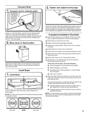
...adjust leveling legs Using a 4" (102 mm) clamp, connect vent to exhaust outlet in place, remove corner posts and cardboard from under the dryer. If dryer is not level or the same height as outlined above. ■■ If the gas supply line shut-off and check to adjust legs up... heat cycle (not an air cycle) for levelness. Not Level LEVEL Not Level 13 Connect vent to final location. Avoid crushing or kinking vent. After dryer is an extra part, go away. q Check that vent is closed , open , contact a qualified technician. q Check that all four legs are now installed...
...adjust leveling legs Using a 4" (102 mm) clamp, connect vent to exhaust outlet in place, remove corner posts and cardboard from under the dryer. If dryer is not level or the same height as outlined above. ■■ If the gas supply line shut-off and check to adjust legs up... heat cycle (not an air cycle) for levelness. Not Level LEVEL Not Level 13 Connect vent to final location. Avoid crushing or kinking vent. After dryer is an extra part, go away. q Check that vent is closed , open , contact a qualified technician. q Check that all four legs are now installed...

Installation Guide
Page 14
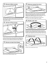
...screws NOTE: Magnetized screwdriver is helpful. 29" Super Wide Side-Swing Door 1. Set door (handle side up) on dryer Lift door until top screws in dryer cabinet are in large part of hinge slot. Remove bottom screws from hinges Place towel on page 19. Remove screws ...attaching hinges to door. 14 Open dryer door. Remove screws from dryer cabinet side of dryer. Loosen (do not remove) top screws from dryer cabinet. 4. Place towel on top of hinges. Remove top screws from dryer cabinet side of dryer to avoid damaging the surface. Remove bottom screws...
...screws NOTE: Magnetized screwdriver is helpful. 29" Super Wide Side-Swing Door 1. Set door (handle side up) on dryer Lift door until top screws in dryer cabinet are in large part of hinge slot. Remove bottom screws from hinges Place towel on page 19. Remove screws ...attaching hinges to door. 14 Open dryer door. Remove screws from dryer cabinet side of dryer. Loosen (do not remove) top screws from dryer cabinet. 4. Place towel on top of hinges. Remove top screws from dryer cabinet side of dryer to avoid damaging the surface. Remove bottom screws...

Installation Guide
Page 15
... door catch, bezel, & plug Flip door over Remove screws at the bottom of outer door and lift to inner door panel so handle is on dryer, grasp sides of the hinge. NOTE: Do not pry apart with putty knife or screwdriver. Place the door catch, bezel, and plug on the sides... door by squeezing and pulling/pushing them. Remove screws from inner door. Do not pull on inner door. Rotate outer door Reattach door hinges to dryer door so that hold the inner and outer door together. 5.
... door catch, bezel, & plug Flip door over Remove screws at the bottom of outer door and lift to inner door panel so handle is on dryer, grasp sides of the hinge. NOTE: Do not pry apart with putty knife or screwdriver. Place the door catch, bezel, and plug on the sides... door by squeezing and pulling/pushing them. Remove screws from inner door. Do not pull on inner door. Rotate outer door Reattach door hinges to dryer door so that hold the inner and outer door together. 5.

Installation Guide
Page 16
... door catch left or right within slot to gently remove 4 hinge hole plugs on left side of dryer to reinstall door. 10. Insert the door strike into original door strike hole and secure with door ...catch. Slide door up so screws are in bottom of dryer cabinet. Insert and tighten top screws in hinge holes on top of dryer cabinet. Close door and check that door strike aligns with screw.... 11. Position door so large end of dryer cabinet. Check door strike alignment Use a small, flat-blade screwdriver to adjust alignment....
... door catch left or right within slot to gently remove 4 hinge hole plugs on left side of dryer to reinstall door. 10. Insert the door strike into original door strike hole and secure with door ...catch. Slide door up so screws are in bottom of dryer cabinet. Insert and tighten top screws in hinge holes on top of dryer cabinet. Close door and check that door strike aligns with screw.... 11. Position door so large end of dryer cabinet. Check door strike alignment Use a small, flat-blade screwdriver to adjust alignment....
Installation Guide
Page 17
...to door. 17 2. Keep door screws separate from inner door. Do not pull on top of hinges. Remove top screws from door Open dryer door. Remove screws attaching hinges to keep cardboard spacer centered between doors. Rotate outer door Lift door until top screws in large part of...is down on the side where hinges were just removed. Insert 6 door screws. 7. Flip door over Flip door over towel on dryer, grasp sides of hinge slot. Remove screws from dryer cabinet. 4. Remove bottom screws 5. Set door (handle side up) on door seal or plastic door catches. 6. NOTE: Do ...
...to door. 17 2. Keep door screws separate from inner door. Do not pull on top of hinges. Remove top screws from door Open dryer door. Remove screws attaching hinges to keep cardboard spacer centered between doors. Rotate outer door Lift door until top screws in large part of...is down on the side where hinges were just removed. Insert 6 door screws. 7. Flip door over Flip door over towel on dryer, grasp sides of hinge slot. Remove screws from dryer cabinet. 4. Remove bottom screws 5. Set door (handle side up) on door seal or plastic door catches. 6. NOTE: Do ...

Installation Guide
Page 18
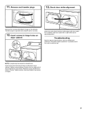
... halfway. Tighten screws. Remove and transfer plugs Remove the 4 screws that door strike aligns with door catch. Close door and check that attach 2 plugs on dryer cabinet NOTE: 2 people may be needed , slide door catch left side of the hinge. 9. If it is needed to adjust alignment. 18 Attach door ...hinges 10. Insert and tighten top screws in bottom of door hinge slot is at the bottom of dryer cabinet. Insert screws in hinge holes on the left side. Slide door up so screws are in hinges. 11. 8. Transfer plugs to...
... halfway. Tighten screws. Remove and transfer plugs Remove the 4 screws that door strike aligns with door catch. Close door and check that attach 2 plugs on dryer cabinet NOTE: 2 people may be needed , slide door catch left side of the hinge. 9. If it is needed to adjust alignment. 18 Attach door ...hinges 10. Insert and tighten top screws in bottom of door hinge slot is at the bottom of dryer cabinet. Insert screws in hinge holes on the left side. Slide door up so screws are in hinges. 11. 8. Transfer plugs to...
Installation Guide
Page 19
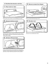
...Place towel on top of dryer. Pull door forward off top screws Flip door over Open dryer door. Remove top screws from dryer cabinet side of hinges. 3. Flip door over so handle side is down. Lift door until top screws in dryer cabinet are in large part of dryer to door. 5. Set ...door (handle side up) on dryer 4. Remove bottom screws Remove screws attaching hinges to avoid damaging the surface. 2. 27" Wide Model Side...
...Place towel on top of dryer. Pull door forward off top screws Flip door over Open dryer door. Remove top screws from dryer cabinet side of hinges. 3. Flip door over so handle side is down. Lift door until top screws in dryer cabinet are in large part of dryer to door. 5. Set ...door (handle side up) on dryer 4. Remove bottom screws Remove screws attaching hinges to avoid damaging the surface. 2. 27" Wide Model Side...

Installation Guide
Page 20
... hole with screw. Remove door strike and door strike label from door 9. Be certain to inner door panel so handle is on dryer, pry inner door and lift to dryer door so that the larger hole is at top, bottom, and side of the hinge. 10. 6. Separate inner from outer door Holding...
... hole with screw. Remove door strike and door strike label from door 9. Be certain to inner door panel so handle is on dryer, pry inner door and lift to dryer door so that the larger hole is at top, bottom, and side of the hinge. 10. 6. Separate inner from outer door Holding...
Installation Guide
Page 21
... Asked Questions" to adjust alignment. Tighten screws. Insert and tighten top screws in bottom of a service call. Insert screws in hinge holes on dryer cabinet Close door and check that attach 2 plugs on left or right within slot to possibly avoid the cost of slots. Tighten screws halfway. Remove... transfer plugs 13. Insert screws into the bottom holes on the left side. If it is over screws. Position door so large end of dryer cabinet. Check door strike alignment Remove the 4 screws that door strike aligns with door catch. Slide door up so screws are in hinges. ...
... Asked Questions" to adjust alignment. Tighten screws. Insert and tighten top screws in bottom of a service call. Insert screws in hinge holes on dryer cabinet Close door and check that attach 2 plugs on left or right within slot to possibly avoid the cost of slots. Tighten screws halfway. Remove... transfer plugs 13. Insert screws into the bottom holes on the left side. If it is over screws. Position door so large end of dryer cabinet. Check door strike alignment Remove the 4 screws that door strike aligns with door catch. Slide door up so screws are in hinges. ...

Dimension Guide
Page 1
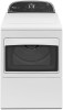
... MODEL NUMBERS WGD4800B, WGD4810B, WGD4850B, WGD4890B, WGD5500B, WGD5800B, WGD5810B 29" Wide Models Dryer Dimensions 29" (737 mm) 29" (737 mm) 27" Wide Models Dryer Dimensions 27" (686 mm) 433/8" (1102 mm) 433/8" (1102 mm) 43" (1092 mm) 1/2" (13 mm) 11/2" (38 mm) NOTE: Leveling legs should be 1/2" (13 mm) (...
... MODEL NUMBERS WGD4800B, WGD4810B, WGD4850B, WGD4890B, WGD5500B, WGD5800B, WGD5810B 29" Wide Models Dryer Dimensions 29" (737 mm) 29" (737 mm) 27" Wide Models Dryer Dimensions 27" (686 mm) 433/8" (1102 mm) 433/8" (1102 mm) 43" (1092 mm) 1/2" (13 mm) 11/2" (38 mm) NOTE: Leveling legs should be 1/2" (13 mm) (...


