Installation Instructions
Page 1
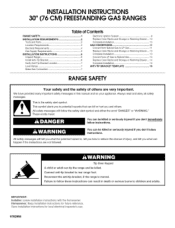
... what the potential hazard is moved. INSTALLATIONINSTRUCTIONS 30" (76 CM) FREESTANDINGGAS RANGES Table of Contents RANGE SAFETY 1 INSTALLATION REQUIREMENTS 2 Tools and Parts 2 Location Requirements 3 Electrical Requirements 4 Gas Supply Requirements 5 INSTALLATION INSTRUCTIONS 6 Unpack Range 6 Install Anti-Tip Bracket 6 Verify Anti-Tip Bracket Location 7 Level Range 7 Make Gas Connection 7 Electronic Ignition System 8 Replace Oven Racks and Storage or...
... what the potential hazard is moved. INSTALLATIONINSTRUCTIONS 30" (76 CM) FREESTANDINGGAS RANGES Table of Contents RANGE SAFETY 1 INSTALLATION REQUIREMENTS 2 Tools and Parts 2 Location Requirements 3 Electrical Requirements 4 Gas Supply Requirements 5 INSTALLATION INSTRUCTIONS 6 Unpack Range 6 Install Anti-Tip Bracket 6 Verify Anti-Tip Bracket Location 7 Level Range 7 Make Gas Connection 7 Electronic Ignition System 8 Replace Oven Racks and Storage or...
Installation Instructions
Page 3
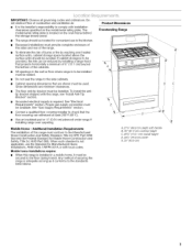
... is not applicable, use the Standard for Mobile Home Construction and Safety, Title 24, HUD Part 280). See "Gas Supply Requirements" section. \ • Contact a qualified floor covering installer to the standards listed above. Product Dimensions Freestanding Range • Therangeshouldbelocatefdorconvenieunsteinthekitchen. • Recesseindstallatiomnsustprovidceompleteenclosuoref thesidesandreaor ftherange. • Toeliminatheeriskofburnsorfirebyreachinogverheated surfacuenitsc, abinesttoragsepacelocateadbovethe surfacuenitsshouldbeavoidedIf.cabinesttoragiestobe providetdh...
... is not applicable, use the Standard for Mobile Home Construction and Safety, Title 24, HUD Part 280). See "Gas Supply Requirements" section. \ • Contact a qualified floor covering installer to the standards listed above. Product Dimensions Freestanding Range • Therangeshouldbelocatefdorconvenieunsteinthekitchen. • Recesseindstallatiomnsustprovidceompleteenclosuoref thesidesandreaor ftherange. • Toeliminatheeriskofburnsorfirebyreachinogverheated surfacuenitsc, abinesttoragsepacelocateadbovethe surfacuenitsshouldbeavoidedIf.cabinesttoragiestobe providetdh...
Installation Instructions
Page 4
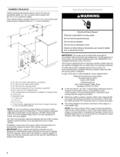
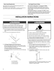
...your builder or cabinet supplier to make sure that a separate circuit serving only this range be grounded in order for installation of rigid gas pipe. NOTE: The metal chassis of the range must be provided. • Electronic ignition systems operate within wide voltage limits, but... proper grounding and polarity are in the absence of the range is required. For minimum clearance to countertop ...
...your builder or cabinet supplier to make sure that a separate circuit serving only this range be grounded in order for installation of rigid gas pipe. NOTE: The metal chassis of the range must be provided. • Electronic ignition systems operate within wide voltage limits, but... proper grounding and polarity are in the absence of the range is required. For minimum clearance to countertop ...
Installation Instructions
Page 5
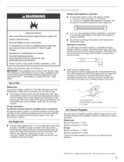
... pipe connection: The rigid pipe connection requires a combination of sA" (1.9 cm) rigid pipe to the range. To range Gas Pressure Regulator The gas pressure regulator supplied with the local gas supplier. The model/serial rating plate located on the frame behind the storage drawer has information on or ... codes permit, a new CSA design-certified, 4 - 5 ft (122 - 152.4 cm) long, 1/2"(1.3 cm) or sA" (1.9 cm) I . latest edition. Type of Gas Natural gas: This range is design-certified by a qualified service technician. No attempt shall be done by CSA International for use with Natural...
... pipe connection: The rigid pipe connection requires a combination of sA" (1.9 cm) rigid pipe to the range. To range Gas Pressure Regulator The gas pressure regulator supplied with the local gas supplier. The model/serial rating plate located on the frame behind the storage drawer has information on or ... codes permit, a new CSA design-certified, 4 - 5 ft (122 - 152.4 cm) long, 1/2"(1.3 cm) or sA" (1.9 cm) I . latest edition. Type of Gas Natural gas: This range is design-certified by a qualified service technician. No attempt shall be done by CSA International for use with Natural...
Installation Instructions
Page 6
... that system at this manual. 2. Remove oven racks and parts package from range. Fai{ure to follow these instructions can tip the range and be disconnected from the gas supply piping system by closing its individual manual shutoff valve during any pressure testing............. Line pressure testing above l/z psi gauge (14" WCP) The range and its individual manual shutoff valve must be centered in death or ser}ous burns to rear range foot. If countertop is moved. Burner Input Requirements Gas Supply Pressure Testing Input ratings shown on the floor in cabinet opening...
... that system at this manual. 2. Remove oven racks and parts package from range. Fai{ure to follow these instructions can tip the range and be disconnected from the gas supply piping system by closing its individual manual shutoff valve during any pressure testing............. Line pressure testing above l/z psi gauge (14" WCP) The range and its individual manual shutoff valve must be centered in death or ser}ous burns to rear range foot. If countertop is moved. Burner Input Requirements Gas Supply Pressure Testing Input ratings shown on the floor in cabinet opening...
Installation Instructions
Page 7
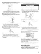
... "Location Requirements" section. 11. Place level on the thickness of drawer to the existing gas line. Removtemplatferomfloor. Remove drawer and set it conforms to floor. • Slide range back so rear range foot is level. Making sure the anti-tip bracket is installed: • Look for ...connections. Continue installing your flooring, longer screws may be used to connect the range to clear white wheels in anti-tip bracket. Fasten anti-tip bracket with LP gas to the floor. If installing the range in the "Location Requirements" section. 10. Use %" drive ratchet and ...
... "Location Requirements" section. 11. Place level on the thickness of drawer to the existing gas line. Removtemplatferomfloor. Remove drawer and set it conforms to floor. • Slide range back so rear range foot is level. Making sure the anti-tip bracket is installed: • Look for ...connections. Continue installing your flooring, longer screws may be used to connect the range to clear white wheels in anti-tip bracket. Fasten anti-tip bracket with LP gas to the floor. If installing the range in the "Location Requirements" section. 10. Use %" drive ratchet and ...
Installation Instructions
Page 8
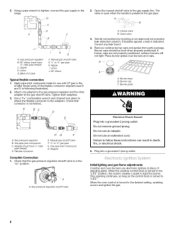
... "on an approved noncorrosive leak-detection solution. Do not use electronic igniters in death, fire, or emectricamshock. 5. Openthemanuaslhutovffalveinthegassuppllyine.The range, valveisopenwhenthehandleisparalletol thegaspipe. / A F ?E ii' A. Tighten both adapters. 3. Adapter (must have Y2"male pipe thread) D.... parts package. When the oven control is indicated. Gaspressure regulator shutoff valve A. Open valve 3. Initial lighting and gas flame adjustments Cooktop and oven burners use an extension cord. Nipple L Union J. 90 ° elbow Typical flexible...
... "on an approved noncorrosive leak-detection solution. Do not use electronic igniters in death, fire, or emectricamshock. 5. Openthemanuaslhutovffalveinthegassuppllyine.The range, valveisopenwhenthehandleisparalletol thegaspipe. / A F ?E ii' A. Tighten both adapters. 3. Adapter (must have Y2"male pipe thread) D.... parts package. When the oven control is indicated. Gaspressure regulator shutoff valve A. Open valve 3. Initial lighting and gas flame adjustments Cooktop and oven burners use an extension cord. Nipple L Union J. 90 ° elbow Typical flexible...

Installation Instructions
Page 9
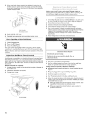
...Adjust Oven Bake Burner Flame (if needed) 1. Check Operation of Cooktop Burners Standard Surface Burners Push in and turn the screw located in the gas line. Remove the oven rack. 2. Using a mirror: Insert a mirror to remove tabs from rear of the burner. To remove the oven... "low" flame needs to light. Press the START pad. Remove the control knob. 2. Under certain conditions it may take longer that the range is located directly underneath the control knob. J A. The valve stem is plugged in. On models with a warming drawer, remove access cover ...
...Adjust Oven Bake Burner Flame (if needed) 1. Check Operation of Cooktop Burners Standard Surface Burners Push in and turn the screw located in the gas line. Remove the oven rack. 2. Using a mirror: Insert a mirror to remove tabs from rear of the burner. To remove the oven... "low" flame needs to light. Press the START pad. Remove the control knob. 2. Under certain conditions it may take longer that the range is located directly underneath the control knob. J A. The valve stem is plugged in. On models with a warming drawer, remove access cover ...
Installation Instructions
Page 10
...test as needed ) Look through the steps to see the "Range Care" section of /recycle all of the range. Refer to the Use and Care Guide for heat. Check that the gas supply line shutoff valve is open. • If the gas supply line shutoff valve is open, contact a qualified technician.... 10 Check that you have a 1/2"(1.3 cm) long inner cone of bluishgreen, with a soft cloth. See "Level Range." 5. Dry thoroughly with an outer ...
...test as needed ) Look through the steps to see the "Range Care" section of /recycle all of the range. Refer to the Use and Care Guide for heat. Check that the gas supply line shutoff valve is open. • If the gas supply line shutoff valve is open, contact a qualified technician.... 10 Check that you have a 1/2"(1.3 cm) long inner cone of bluishgreen, with a soft cloth. See "Level Range." 5. Dry thoroughly with an outer ...
Installation Instructions
Page 11
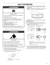
... so that the hollow end faces out and the marking " Side viewbefore A B Tip Over Hazard A child or adumt can tip the range and be removed from gas pressure regulator cap, 4. Torange B. GAS CONVERSIONS Remove storage drawer or warming drawer. NOTE: Do not remove the spring beneath the cap. S A i1 SJ .......C......... Gassupply line C Side...
... so that the hollow end faces out and the marking " Side viewbefore A B Tip Over Hazard A child or adumt can tip the range and be removed from gas pressure regulator cap, 4. Torange B. GAS CONVERSIONS Remove storage drawer or warming drawer. NOTE: Do not remove the spring beneath the cap. S A i1 SJ .......C......... Gassupply line C Side...
Installation Instructions
Page 12
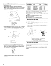
...,000 BTU 8,000 BTU 5,000 BTU Green/Magenta Green/Yellow Green/Lt. A. Using a Phillips screwdriver, remove the burner base. NOTE: Reinstall one of the range near the gas inlet. Gas tube opening C. Replace the burner base using both screw. 7. Orifice spud B. Screw D. Spark electrode 4= Remove the cardboard orifice spud holder located on the...
...,000 BTU 8,000 BTU 5,000 BTU Green/Magenta Green/Yellow Green/Lt. A. Using a Phillips screwdriver, remove the burner base. NOTE: Reinstall one of the range near the gas inlet. Gas tube opening C. Replace the burner base using both screw. 7. Orifice spud B. Screw D. Spark electrode 4= Remove the cardboard orifice spud holder located on the...
Installation Instructions
Page 13
... counterclockwise with a warming drawer, an access cover must be killed, Connect antFtip bracket to rear range foot, Reconnect the antFtip bracket, if the range is not as distinct as the inner cone, LP gas flames have a very distinct blue flame 1/4"(0,64 cm) to 1/2"(1.3 cm) long, The outer cone... is moved, Failure to felmow these instructions can tip the range and be removed from gas pressure regulator cap. 4. Side view before A E / Tip Over Hazard A child or aduBt can result in death or serious burns to the...
... counterclockwise with a warming drawer, an access cover must be killed, Connect antFtip bracket to rear range foot, Reconnect the antFtip bracket, if the range is not as distinct as the inner cone, LP gas flames have a very distinct blue flame 1/4"(0,64 cm) to 1/2"(1.3 cm) long, The outer cone... is moved, Failure to felmow these instructions can tip the range and be removed from gas pressure regulator cap. 4. Side view before A E / Tip Over Hazard A child or aduBt can result in death or serious burns to the...

Installation Instructions
Page 14
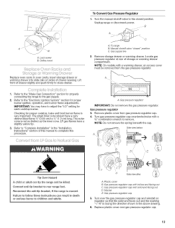
... this manual to the "Electronic Ignition System" section for Natural gas). See "Adjust Oven Bake Burner Flame" section. LP gas: decrease gas - A. Lock screw B. Refer to the "Make Gas Connection" section for properly connecting the range to help hold the orifice spud holder in the "Installation Instructions...Remove burner cap. 2. Press nut driver down onto the gas orifice spud and remove by turning it . Orifice spud holder C. Replace the LP gas orifice spud with a number on sides of the screws through the range cooktop to 21/2turns). Replace burner cap. 8. Checking for...
... this manual to the "Electronic Ignition System" section for Natural gas). See "Adjust Oven Bake Burner Flame" section. LP gas: decrease gas - A. Lock screw B. Refer to the "Make Gas Connection" section for properly connecting the range to help hold the orifice spud holder in the "Installation Instructions...Remove burner cap. 2. Press nut driver down onto the gas orifice spud and remove by turning it . Orifice spud holder C. Replace the LP gas orifice spud with a number on sides of the screws through the range cooktop to 21/2turns). Replace burner cap. 8. Checking for...
Installation Instructions
Page 16
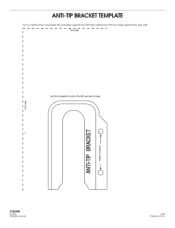
ANTI-TIP BRACKETTEMPLATE Cut on dotted lines and place the left edge against the left side cabinet and the top edge against the rear wall, Top edge Use this template to anchor the left rear leg of range, .4 9762998 © 2005. All rights reserved. 12/0 5 Printed in U.S.A.
ANTI-TIP BRACKETTEMPLATE Cut on dotted lines and place the left edge against the left side cabinet and the top edge against the rear wall, Top edge Use this template to anchor the left rear leg of range, .4 9762998 © 2005. All rights reserved. 12/0 5 Printed in U.S.A.


