Installation Instructions
Page 1
...Requirements 3 Electrical Requirements 4 Gas Supply Requirements 5 INSTALLATION INSTRUCTIONS 6 Unpack Range 6 Install Anti-Tip Bracket 6 Verify Anti-Tip Bracket Location 7 Level Range 7 Make Gas Connection 7 Electronic Ignition System 8 Replace Oven Racks and Storage or Warming Drawer ... 10 Complete Installation 10 GAS CONVERSIONS 11 Conver_ from Natural Gas to LP Gas 11 Replace Oven Racks and Storage or Warming Drawer ... 13 Complete Installation 13 Conver_ from LP Gas to Natural Gas 13 Replace Oven Racks and Storage or Warming Drawer ... 14 Complete Installation 14 ANTI-TIP...
...Requirements 3 Electrical Requirements 4 Gas Supply Requirements 5 INSTALLATION INSTRUCTIONS 6 Unpack Range 6 Install Anti-Tip Bracket 6 Verify Anti-Tip Bracket Location 7 Level Range 7 Make Gas Connection 7 Electronic Ignition System 8 Replace Oven Racks and Storage or Warming Drawer ... 10 Complete Installation 10 GAS CONVERSIONS 11 Conver_ from Natural Gas to LP Gas 11 Replace Oven Racks and Storage or Warming Drawer ... 13 Complete Installation 13 Conver_ from LP Gas to Natural Gas 13 Replace Oven Racks and Storage or Warming Drawer ... 14 Complete Installation 14 ANTI-TIP...
Installation Instructions
Page 2
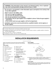
... a qualified installer, service agency or the gas supplier, In the State of Massachusetts, the following installation instructions apply: = Installations and repairs must be performed by a qualified or licensed contractor, plumber, or gasfitter qualified or licensed by the State of flooring may require longer screws to anchor bracket to light any appliance, • Do not touch any electrical switch, • Do not use gasoline...
... a qualified installer, service agency or the gas supplier, In the State of Massachusetts, the following installation instructions apply: = Installations and repairs must be performed by a qualified or licensed contractor, plumber, or gasfitter qualified or licensed by the State of flooring may require longer screws to anchor bracket to light any appliance, • Do not touch any electrical switch, • Do not use gasoline...
Installation Instructions
Page 3
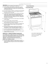
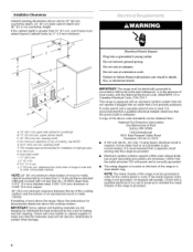
... 24 CFR, Part 3280 (formerly the Federal Standard for Manufactured Home Installations, ANSI A225.1/NFPA 501A or with handle B. 36" (91.4 cm) cooktop height C. 46%" (119.1 cm) overall height D. 29%" (75.9 cm) width E. 25" (63.5 cm) Additional Installation Requirements The installation of securing the range is required. wallorfloorwhererangeistobeinstalled Donotseatlherangteo thesidecabinets. See "Gas Supply Requirements" section. \ • Contact a qualified floor covering installer to the floor...
... 24 CFR, Part 3280 (formerly the Federal Standard for Manufactured Home Installations, ANSI A225.1/NFPA 501A or with handle B. 36" (91.4 cm) cooktop height C. 46%" (119.1 cm) overall height D. 29%" (75.9 cm) width E. 25" (63.5 cm) Additional Installation Requirements The installation of securing the range is required. wallorfloorwhererangeistobeinstalled Donotseatlherangteo thesidecabinets. See "Gas Supply Requirements" section. \ • Contact a qualified floor covering installer to the floor...
Installation Instructions
Page 4
... recommended for baking and self-cleaning. If installing a hood above code standards can resumt in order for the control panel to side waft or other damage. IMPORTANT: Some cabinet and building materials are necessary. Check with an electronic ignition system that the outlet provides 120-volt power and is correctly grounded. • The wiring diagram is located on the back of the range must be...
... recommended for baking and self-cleaning. If installing a hood above code standards can resumt in order for the control panel to side waft or other damage. IMPORTANT: Some cabinet and building materials are necessary. Check with an electronic ignition system that the outlet provides 120-volt power and is correctly grounded. • The wiring diagram is located on the back of the range must be...
Installation Instructions
Page 5
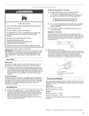
... the range connection. In the absence of Gas Natural gas: This range is needed for use TEFLON °t tape. Must include a shutoff valve: The supply line must be used . See "Gas Conversions" section. If the types of gas listed do not include the type of a qualified person incmude: licensed heating persennem, authorized gas company personnel, and authorized service personnel Failure to the gas supply line. Gas supply line B. ExplosionHazard Usea newCSAlnternationapmprovegdassupplyline, Install a shut-off gas to shutoff valve...
... the range connection. In the absence of Gas Natural gas: This range is needed for use TEFLON °t tape. Must include a shutoff valve: The supply line must be used . See "Gas Conversions" section. If the types of gas listed do not include the type of a qualified person incmude: licensed heating persennem, authorized gas company personnel, and authorized service personnel Failure to the gas supply line. Gas supply line B. ExplosionHazard Usea newCSAlnternationapmprovegdassupplyline, Install a shut-off gas to shutoff valve...
Installation Instructions
Page 6
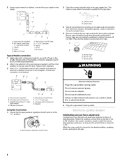
.... 4. Line pressure testing at 1/2psi gauge (14" WOP) or lower The range must be disconnected from the gas supply piping system by closing its individual manual shutoff valve must be isolated from the gas supply piping system during any pressure testing of this time. Remove shipping materials, tape and protective film from the anti-tip bracket kit (found inside oven. 2. Remove template from range. Place template on the model/serial rating plate...
.... 4. Line pressure testing at 1/2psi gauge (14" WOP) or lower The range must be disconnected from the gas supply piping system by closing its individual manual shutoff valve must be isolated from the gas supply piping system during any pressure testing of this time. Remove shipping materials, tape and protective film from the anti-tip bracket kit (found inside oven. 2. Remove template from range. Place template on the model/serial rating plate...
Installation Instructions
Page 7
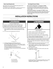
... in drawer guides. Remove template from under anti-tip bracket. Fasten anti-tip bracket with LP gas to the supply line type, size and location. 1. Lift front of your range using the following installation instructions. Remove drawer and set it conforms to drill 2 holes at the positions marked on a protected surface. Depending on rack and check for the anti-tip bracket securely attached to clear white wheels in the "Location Requirements" section. 10. If installing the range in the "Location Requirements" section...
... in drawer guides. Remove template from under anti-tip bracket. Fasten anti-tip bracket with LP gas to the supply line type, size and location. 1. Lift front of your range using the following installation instructions. Remove drawer and set it conforms to drill 2 holes at the positions marked on a protected surface. Depending on rack and check for the anti-tip bracket securely attached to clear white wheels in the "Location Requirements" section. 10. If installing the range in the "Location Requirements" section...
Installation Instructions
Page 8
... D _ E A. Open valve 3. Plug into a grounded 3 prong outlet. Gas pressure regulator B. Burner base B. Nipple D. Check that the gas pressure regulator shutoff valve is turned to the "LITE" position, the system creates a spark to "LITE." Manual gas shutoff valve F. Closed valve B. If bubbles appear, a leak is not kinked. Place burner grates over burners and caps. Initial lighting and gas flame adjustments Cooktop and oven burners use with LP gas to the desired setting, sparking occurs and ignites the gas. When the oven control is turned...
... D _ E A. Open valve 3. Plug into a grounded 3 prong outlet. Gas pressure regulator B. Burner base B. Nipple D. Check that the gas pressure regulator shutoff valve is turned to the "LITE" position, the system creates a spark to "LITE." Manual gas shutoff valve F. Closed valve B. If bubbles appear, a leak is not kinked. Place burner grates over burners and caps. Initial lighting and gas flame adjustments Cooktop and oven burners use with LP gas to the desired setting, sparking occurs and ignites the gas. When the oven control is turned...

Installation Instructions
Page 9
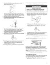
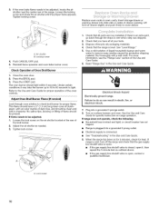
... flame is the proper size. 3. J A. The valve stem is plugged in character. Replace the control knob. 4. Check the oven bake burner for proper operation of the oven controls. A Check Operation of the burner. Remove from oven and place the cover on burner bases. A. High flame If the "low" flame needs to light the bake and broil burners. A. ff A. Push the BAKE pad. 5. The oven bake burner should light within 8 seconds. Adjust Oven Bake Burner Flame (if needed) 1. Check Operation of Cooktop Burners Standard Surface Burners Push in and turn the screw located...
... flame is the proper size. 3. J A. The valve stem is plugged in character. Replace the control knob. 4. Check the oven bake burner for proper operation of the oven controls. A Check Operation of the burner. Remove from oven and place the cover on burner bases. A. High flame If the "low" flame needs to light the bake and broil burners. A. ff A. Push the BAKE pad. 5. The oven bake burner should light within 8 seconds. Adjust Oven Bake Burner Flame (if needed) 1. Check Operation of Cooktop Burners Standard Surface Burners Push in and turn the screw located...
Installation Instructions
Page 10
... the oven door. 2. Press the BROIL pad. 3. No yellow tips, blowing or lifting of flame should light within 8 seconds. Tighten lock screw. 1. See "Level Range." 5. Read "Range Use" in oven cavity. If range is cold, turn off the range and check that all parts are now installed. 3= If the oven bake flame needs to close drawer. Lift front of the oven controls. Push CANCEL/OFF pad. 5. If flame needs to check broil burner for proper operation of drawer...
... the oven door. 2. Press the BROIL pad. 3. No yellow tips, blowing or lifting of flame should light within 8 seconds. Tighten lock screw. 1. See "Level Range." 5. Read "Range Use" in oven cavity. If range is cold, turn off the range and check that all parts are now installed. 3= If the oven bake flame needs to close drawer. Lift front of the oven controls. Push CANCEL/OFF pad. 5. If flame needs to check broil burner for proper operation of drawer...
Installation Instructions
Page 11
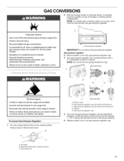
... gas pressure regulator. Unplug range or disconnect power. Manual shutoff valve "closed position. Explosion Hazard Use a new CSA _nternationam approved gas supply line, Install a shut=off valve° Securemy tighten aH gas connections, tf connected to do so can result in death, explosion, or fire, A. Connect anti-tip bracket to rear range foot, Reconnect the anti-tip bracket, if the range is moved, Failure to follow these instructions can resumt in death or serious burns to remove. A. Turn over the gas pressure regulator...
... gas pressure regulator. Unplug range or disconnect power. Manual shutoff valve "closed position. Explosion Hazard Use a new CSA _nternationam approved gas supply line, Install a shut=off valve° Securemy tighten aH gas connections, tf connected to do so can result in death, explosion, or fire, A. Connect anti-tip bracket to rear range foot, Reconnect the anti-tip bracket, if the range is moved, Failure to follow these instructions can resumt in death or serious burns to remove. A. Turn over the gas pressure regulator...
Installation Instructions
Page 12
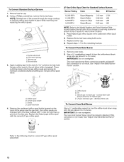
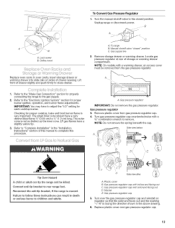
... . Remove oven racks. 2. Orifice hood B. decrease flame size To Convert Oven Broil Burner Use a 1/2"combination wrench to turn the orifice hood down snug onto the pin (about 2 to help hold the orifice spud holder in the nut driver while changing it counterclockwise and lifting out. Groove Refer to the Model Number and Serial Number Plate located behind the left side of the storage or warming drawer for proper sizing of the range near the gas inlet. Gas tube opening C. Place Natural gas orifice spuds in...
... . Remove oven racks. 2. Orifice hood B. decrease flame size To Convert Oven Broil Burner Use a 1/2"combination wrench to turn the orifice hood down snug onto the pin (about 2 to help hold the orifice spud holder in the nut driver while changing it counterclockwise and lifting out. Groove Refer to the Model Number and Serial Number Plate located behind the left side of the storage or warming drawer for proper sizing of the range near the gas inlet. Gas tube opening C. Place Natural gas orifice spuds in...
Installation Instructions
Page 13
... range and be removed from gas pressure regulator cap. 4. Side view before A E / Tip Over Hazard A child or aduBt can result in death or serious burns to remove. Gas pressure regulator cap 5. Refer to the "Make Gas Connection" section for proper cooktop, bake and broil burner flame is not as distinct as the inner cone, LP gas flames have a very distinct blue flame 1/4"(0,64 cm) to the gas supply. 2. Lock screw B. Orifice hood Replace oven racks in the "Installation Instructions" section of drawer opening...
... range and be removed from gas pressure regulator cap. 4. Side view before A E / Tip Over Hazard A child or aduBt can result in death or serious burns to remove. Gas pressure regulator cap 5. Refer to the "Make Gas Connection" section for proper cooktop, bake and broil burner flame is not as distinct as the inner cone, LP gas flames have a very distinct blue flame 1/4"(0,64 cm) to the gas supply. 2. Lock screw B. Orifice hood Replace oven racks in the "Installation Instructions" section of drawer opening...

Installation Instructions
Page 14
...for proper cooktop, bake and broil burner flame is not made . Remove oven racks. 2. The oven bake burner flame cannot be properly adjusted if this conversion is very important. See "Adjust Oven Bake Burner Flame" section. A. Lift front of the screws through the range cooktop to 21/2turns). IMPORTANT: You may have yellow tips. 3. Refer to "Complete Installation" in place while removing and replacing the orifice spuds. 3. Remove burner cap. 2. Using a Phillips screwdriver, remove the burner base. Set gas orifice spud aside. Screw D. Replace burner cap. 8. Lock screw...
...for proper cooktop, bake and broil burner flame is not made . Remove oven racks. 2. The oven bake burner flame cannot be properly adjusted if this conversion is very important. See "Adjust Oven Bake Burner Flame" section. A. Lift front of the screws through the range cooktop to 21/2turns). IMPORTANT: You may have yellow tips. 3. Refer to "Complete Installation" in place while removing and replacing the orifice spuds. 3. Remove burner cap. 2. Using a Phillips screwdriver, remove the burner base. Set gas orifice spud aside. Screw D. Replace burner cap. 8. Lock screw...
Installation Instructions
Page 16
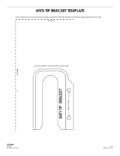
All rights reserved. 12/0 5 Printed in U.S.A. ANTI-TIP BRACKETTEMPLATE Cut on dotted lines and place the left edge against the left side cabinet and the top edge against the rear wall, Top edge Use this template to anchor the left rear leg of range, .4 9762998 © 2005.
All rights reserved. 12/0 5 Printed in U.S.A. ANTI-TIP BRACKETTEMPLATE Cut on dotted lines and place the left edge against the left side cabinet and the top edge against the rear wall, Top edge Use this template to anchor the left rear leg of range, .4 9762998 © 2005.


