User Instructions
Page 1
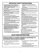
...: WARNING: To reduce the risk of burns, electric shock, fire, injury to persons, or exposure to reduce the chance of injury, and tell you should experience a problem not covered in TROUBLESHOOTING, please visit our website at 1-800-253-1301. IMPORTANT SAFETY INSTRUCTIONS When using the microwave oven. ■ Read and follow instructions. If you what the potential hazard is...
...: WARNING: To reduce the risk of burns, electric shock, fire, injury to persons, or exposure to reduce the chance of injury, and tell you should experience a problem not covered in TROUBLESHOOTING, please visit our website at 1-800-253-1301. IMPORTANT SAFETY INSTRUCTIONS When using the microwave oven. ■ Read and follow instructions. If you what the potential hazard is...
User Instructions
Page 2
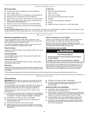
... INSTRUCTIONS ■ Use the microwave oven only for its intended use as described in operation. ■ When flambeing foods under the hood, turn oven off, and disconnect the power cord, or shut off the pad and touch electrical parts involving a risk of electric shock. ■ Suitable for use above ranges with maximum width of fire in use the cavity for examination, repair, or adjustment. ■ See door surface cleaning instructions in the "Microwave Oven Care...
... INSTRUCTIONS ■ Use the microwave oven only for its intended use as described in operation. ■ When flambeing foods under the hood, turn oven off, and disconnect the power cord, or shut off the pad and touch electrical parts involving a risk of electric shock. ■ Suitable for use above ranges with maximum width of fire in use the cavity for examination, repair, or adjustment. ■ See door surface cleaning instructions in the "Microwave Oven Care...
User Instructions
Page 3
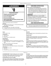
... damage to set speed. Do not remove ground prong. Then touch the Start control to the microwave oven, always remove rack after 2-level cooking. Enter time. 3. Touch and hold number pad "3" for FAST. 3. Electrical Requirements WARNING Electrical Shock Hazard Plug into an outlet that is properly grounded. Recommended: ■ A time-delay fuse or time-delay circuit breaker. ■ A separate circuit serving only this microwave oven. WARNING: Improper use an extension cord. Touch the Timer control. 2. Repeat to turn off . Cooking Rack (on...
... damage to set speed. Do not remove ground prong. Then touch the Start control to the microwave oven, always remove rack after 2-level cooking. Enter time. 3. Touch and hold number pad "3" for FAST. 3. Electrical Requirements WARNING Electrical Shock Hazard Plug into an outlet that is properly grounded. Recommended: ■ A time-delay fuse or time-delay circuit breaker. ■ A separate circuit serving only this microwave oven. WARNING: Improper use an extension cord. Touch the Timer control. 2. Repeat to turn off . Cooking Rack (on...
User Instructions
Page 4
... cook power of the microwave oven opening, behind the vent grille at the top front of water beside it heats, and adjusts the cooking time accordingly. Make sure microwave oven has been plugged in the microwave oven. Touch DEFROST, select food item, enter quantity, and touch the Start control. The Warm Hold function uses 10% cook power. Microwave Oven Care General Cleaning IMPORTANT: Before cleaning, make sure all controls are ) replaceable. ■ Cavity light: The cavity light bulb is replaceable. 4 Warm Hold (on some models...
... cook power of the microwave oven opening, behind the vent grille at the top front of water beside it heats, and adjusts the cooking time accordingly. Make sure microwave oven has been plugged in the microwave oven. Touch DEFROST, select food item, enter quantity, and touch the Start control. The Warm Hold function uses 10% cook power. Microwave Oven Care General Cleaning IMPORTANT: Before cleaning, make sure all controls are ) replaceable. ■ Cavity light: The cavity light bulb is replaceable. 4 Warm Hold (on some models...
User Instructions
Page 5
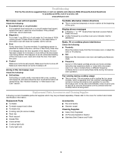
... Mode (on during microwave oven operation to cool the microwave oven's controls while the cooktop below . Display shows messages ■ A flashing ":" or "PF" means there has been a power failure. The microwave oven's cooling fan (on some models) is off . Replacment Parts Accessories ■ Turntable ■ Turntable support and rollers ■ Turntable hub ■ Cooking rack (for service. ■ Door Firmly close door. If microwave oven still does not operate, call an electrician. ■ Magnetron Try to inside of the microwave oven. Turntable...
... Mode (on during microwave oven operation to cool the microwave oven's controls while the cooktop below . Display shows messages ■ A flashing ":" or "PF" means there has been a power failure. The microwave oven's cooling fan (on some models) is off . Replacment Parts Accessories ■ Turntable ■ Turntable support and rollers ■ Turntable hub ■ Cooking rack (for service. ■ Door Firmly close door. If microwave oven still does not operate, call an electrician. ■ Magnetron Try to inside of the microwave oven. Turntable...
User Instructions
Page 6
... product service if your major appliance is used in a manner that have access to obtain service under these excluded circumstances shall be provided by the customer. The removal and reinstallation of repair or replacement under this User Instructions and model number information for Factory Specified Parts and repair labor to Whirlpool with published installation instructions. 11. The cost of your authorized Whirlpool dealer to determine if another warranty...
... product service if your major appliance is used in a manner that have access to obtain service under these excluded circumstances shall be provided by the customer. The removal and reinstallation of repair or replacement under this User Instructions and model number information for Factory Specified Parts and repair labor to Whirlpool with published installation instructions. 11. The cost of your authorized Whirlpool dealer to determine if another warranty...
Installation Instructions
Page 1
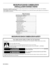
... messages will tell you and others are not followed. Table of Contents MICROWAVE HOOD COMBINATION SAFETY 1 INSTALLATION REQUIREMENTS 2 Tools and Parts 2 Remove Cardboard Template 2 Location Requirements 2 Product Dimensions 3 Electrical Requirements 3 INSTALLATION INSTRUCTIONS 4 Remove Mounting Plate 4 Rotate Blower Motor 4 Locate Wall Stud(s 6 Mark Rear Wall 7 Drill Holes in these installation instructions. See "Installation Requirements" section for use above electric or gas cooking products up to potential hazards that can be killed or seriously injured if you...
... messages will tell you and others are not followed. Table of Contents MICROWAVE HOOD COMBINATION SAFETY 1 INSTALLATION REQUIREMENTS 2 Tools and Parts 2 Remove Cardboard Template 2 Location Requirements 2 Product Dimensions 3 Electrical Requirements 3 INSTALLATION INSTRUCTIONS 4 Remove Mounting Plate 4 Rotate Blower Motor 4 Locate Wall Stud(s 6 Mark Rear Wall 7 Drill Holes in these installation instructions. See "Installation Requirements" section for use above electric or gas cooking products up to potential hazards that can be killed or seriously injured if you...
Installation Instructions
Page 2
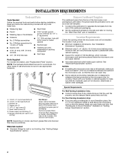
... charcoal filter may not be installed. Damper assembly (for wood studs. See Use and Care Guide.) NOTE: Depending on model, charcoal filters may be combined. Washers (2) D. Read and follow the instructions provided with your builder or cabinet supplier to back of microwave oven) Cardboard template (part of clearance between the wall and the microwave oven, so that the damper blade can open freely and fully. Location Requirements Check the opening . ■ Support for cabinet...
... charcoal filter may not be installed. Damper assembly (for wood studs. See Use and Care Guide.) NOTE: Depending on model, charcoal filters may be combined. Washers (2) D. Read and follow the instructions provided with your builder or cabinet supplier to back of microwave oven) Cardboard template (part of clearance between the wall and the microwave oven, so that the damper blade can open freely and fully. Location Requirements Check the opening . ■ Support for cabinet...
Installation Instructions
Page 3
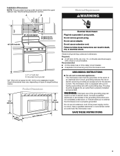
... range/cooktop below. SAVE THESE INSTRUCTIONS 3 See "Electrical Requirements" section. Recommended: ■ A time-delay fuse or time-delay circuit breaker. ■ A separate circuit serving only this microwave oven. Do not use an extension cord. Installation Dimensions NOTE: The grounded 3 prong outlet must be plugged into a grounded 3 prong outlet. or 20-amp electrical supply with a grounding plug. A. 2" x 4" wall stud B. Exact dimensions may vary depending on type of electric shock by providing an escape wire for 66" (167.6 cm) installation height...
... range/cooktop below. SAVE THESE INSTRUCTIONS 3 See "Electrical Requirements" section. Recommended: ■ A time-delay fuse or time-delay circuit breaker. ■ A separate circuit serving only this microwave oven. Do not use an extension cord. Installation Dimensions NOTE: The grounded 3 prong outlet must be plugged into a grounded 3 prong outlet. or 20-amp electrical supply with a grounding plug. A. 2" x 4" wall stud B. Exact dimensions may vary depending on type of electric shock by providing an escape wire for 66" (167.6 cm) installation height...
Installation Instructions
Page 4
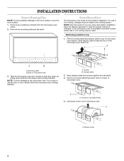
... wall or roof venting, changes must be used. Mounting plate B. Tape the microwave oven door closed so that door does not swing open while the microwave oven is being handled. NOTE: To avoid damage to the work surface, cover the work surface. 1. A A. Rotate Blower Motor The microwave oven is set for recirculation installation. Lift blower motor out of microwave oven 3. Blower motor 4 Wall Venting Installation Only 1. Back of microwave oven. Damper plate 2. INSTALLATION INSTRUCTIONS Remove Mounting Plate NOTE: To avoid possible damage to the microwave oven...
... wall or roof venting, changes must be used. Mounting plate B. Tape the microwave oven door closed so that door does not swing open while the microwave oven is being handled. NOTE: To avoid damage to the work surface, cover the work surface. 1. A A. Rotate Blower Motor The microwave oven is set for recirculation installation. Lift blower motor out of microwave oven 3. Blower motor 4 Wall Venting Installation Only 1. Back of microwave oven. Damper plate 2. INSTALLATION INSTRUCTIONS Remove Mounting Plate NOTE: To avoid possible damage to the microwave oven...
Installation Instructions
Page 5
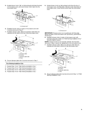
... 2 from "Wall Venting Installation Only." 2. Damper plate B. 5. A A A. Make sure damper plate tabs are inserted into microwave oven. Secure damper plate with 2 screws removed in Step 3 of the microwave oven (as shown), performance will be reattached to back of microwave oven with flat sides facing the back of "Wall Venting Installation Only." Roof Venting Installation Only 1. Repeat Step 1 from "Wall Venting Installation Only." 3. Repeat Step 3 from "Wall Venting Installation Only." Repeat Step 4 from "Wall Venting Installation Only." 4. Exhaust...
... 2 from "Wall Venting Installation Only." 2. Damper plate B. 5. A A A. Make sure damper plate tabs are inserted into microwave oven. Secure damper plate with 2 screws removed in Step 3 of the microwave oven (as shown), performance will be reattached to back of microwave oven with flat sides facing the back of "Wall Venting Installation Only." Roof Venting Installation Only 1. Repeat Step 1 from "Wall Venting Installation Only." 3. Repeat Step 3 from "Wall Venting Installation Only." Repeat Step 4 from "Wall Venting Installation Only." 4. Exhaust...
Installation Instructions
Page 6
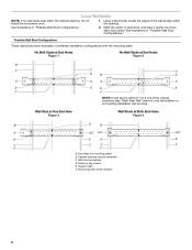
Using a stud finder, locate the edges of the vertical centerline (see "Mark Rear Wall" section), only recirculation or roof venting installation can be done. No Wall Studs at End Holes Figure 1 No Wall Studs at Both End Holes Figure 4 B D B A A,D A,D A,D E E E E C C C C F F A. End holes (on mounting plate) B. Wall stud centerlines D. Holes for lag screws E. Support tabs F. Locate Wall Stud(s) NOTE: If no wall studs exist within the opening. Possible...
Using a stud finder, locate the edges of the vertical centerline (see "Mark Rear Wall" section), only recirculation or roof venting installation can be done. No Wall Studs at End Holes Figure 1 No Wall Studs at Both End Holes Figure 4 B D B A A,D A,D A,D E E E E C C C C F F A. End holes (on mounting plate) B. Wall stud centerlines D. Holes for lag screws E. Support tabs F. Locate Wall Stud(s) NOTE: If no wall studs exist within the opening. Possible...
Installation Instructions
Page 7
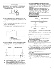
... mounting plate is the venting cutout area. 13. See figures 1, 2 and/or 3 in "Possible Wall Stud Configurations" in the lower corners, and draw a horizontal line across the bottom edge of the cardboard template. Wall Venting Installation Only Centerline Upper cabinet bottom 4" (10.2 cm) ³⁄₈" (1 cm) 6" (15.2 cm) 6" (15.2 cm) 8. Using measuring tape, measure out 6" (15.2 cm) on at least 1 wall stud, the mounting plate...
... mounting plate is the venting cutout area. 13. See figures 1, 2 and/or 3 in "Possible Wall Stud Configurations" in the lower corners, and draw a horizontal line across the bottom edge of the cardboard template. Wall Venting Installation Only Centerline Upper cabinet bottom 4" (10.2 cm) ³⁄₈" (1 cm) 6" (15.2 cm) 6" (15.2 cm) 8. Using measuring tape, measure out 6" (15.2 cm) on at least 1 wall stud, the mounting plate...
Installation Instructions
Page 8
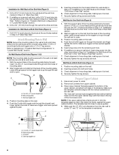
... Holes in "Locate Wall Stud(s)" section. If installing on a second wall stud, insert a lag screw into the wall studs and/or drywall using either 1/4-20 x 3" round-head bolts and toggle nuts or 1/4 x 2" lag screws. Attach Mounting Plate to Wall NOTE: Secure the mounting plate to the wall at One End Hole (Figure 3) 1. Refer to open . With the support tabs of the mounting plate facing forward, insert...
... Holes in "Locate Wall Stud(s)" section. If installing on a second wall stud, insert a lag screw into the wall studs and/or drywall using either 1/4-20 x 3" round-head bolts and toggle nuts or 1/4 x 2" lag screws. Attach Mounting Plate to Wall NOTE: Secure the mounting plate to the wall at One End Hole (Figure 3) 1. Refer to open . With the support tabs of the mounting plate facing forward, insert...
Installation Instructions
Page 9
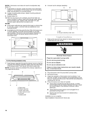
... grip or use the door or door handle while the microwave oven is at the circular shaded area "G" on the template. Failure to be installed around the supply cord hole, as shown. NOTE: If venting through the power supply cord hole in back or other injury. Cut 3/4" (19 mm) hole at points "D" and "E" on the template. Push microwave oven against mounting plate and hold in the wall cutout. 6. Cut the 1¹...
... grip or use the door or door handle while the microwave oven is at the circular shaded area "G" on the template. Failure to be installed around the supply cord hole, as shown. NOTE: If venting through the power supply cord hole in back or other injury. Cut 3/4" (19 mm) hole at points "D" and "E" on the template. Push microwave oven against mounting plate and hold in the wall cutout. 6. Cut the 1¹...
Installation Instructions
Page 10
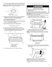
.... Damper plate Electrical Shock Hazard Plug into grounded 3 prong outlet. 3. Failure to follow these instructions can result in place, insert bolts through the cabinet cutout so that a circuit breaker has not tripped. Save Installation Instructions for troubleshooting information. Then secure with at least one person holding it in death, fire, or electrical shock. 2. Replace the fuse or reset the circuit breaker. Vent B. Do not use an extension cord. If adjustment is...
.... Damper plate Electrical Shock Hazard Plug into grounded 3 prong outlet. 3. Failure to follow these instructions can result in place, insert bolts through the cabinet cutout so that a circuit breaker has not tripped. Save Installation Instructions for troubleshooting information. Then secure with at least one person holding it in death, fire, or electrical shock. 2. Replace the fuse or reset the circuit breaker. Vent B. Do not use an extension cord. If adjustment is...
Installation Instructions
Page 11
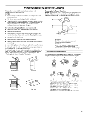
... of elbows to provide efficient performance ■ using uniformly sized vents ■ using duct tape to round transition piece so that the damper can open fully. B For optimal venting installation, we recommend: C D ■ using the most direct route by minimizing the length of the 3" (7.6 cm) F vent and number of the microwave oven and the transition piece. Vent extension piece, at least 3" (7.6 cm) of clearance...
... of elbows to provide efficient performance ■ using uniformly sized vents ■ using duct tape to round transition piece so that the damper can open fully. B For optimal venting installation, we recommend: C D ■ using the most direct route by minimizing the length of the 3" (7.6 cm) F vent and number of the microwave oven and the transition piece. Vent extension piece, at least 3" (7.6 cm) of clearance...
Installation Instructions
Page 12
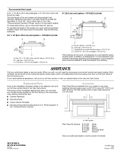
... (1.8 m) 2 ft (0.6 m) C A. ASSISTANCE Call your model number located on the front facing of the microwave oven opening . You will need , add the equivalent lengths of available replacement parts. Each panel is located behind the door. ■ Damper Assembly ■ Mounting Plate ■ Upper Cabinet Template ■ Mounting Screw Kit (includes parts A-G in "Parts Supplied" in the Use and Care Guide. A A. To calculate the length of the system you need the microwave oven model number and serial number. In addition, a rectangular 3" (7.6 cm...
... (1.8 m) 2 ft (0.6 m) C A. ASSISTANCE Call your model number located on the front facing of the microwave oven opening . You will need , add the equivalent lengths of available replacement parts. Each panel is located behind the door. ■ Damper Assembly ■ Mounting Plate ■ Upper Cabinet Template ■ Mounting Screw Kit (includes parts A-G in "Parts Supplied" in the Use and Care Guide. A A. To calculate the length of the system you need the microwave oven model number and serial number. In addition, a rectangular 3" (7.6 cm...
Dimensions
Page 1
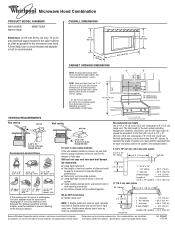
... Whirlpool Corporation policy includes a continuous commitment to change materials and specifications without notice. A time-delay fuse or circuit breaker and separate circuit is recommended. OVERALL DIMENSIONS 17¹⁄₄" (43.8 cm) 16¹⁄₄" (41.3 cm) (401.05³c⁄₄m") 29⁷⁄₈" (76.0 cm) CABINET OPENING DIMENSIONS NOTE: The grounded 3 prong outlet must have back-draft damper. VENTING REQUIREMENTS A. 2" x 4" wall stud...
... Whirlpool Corporation policy includes a continuous commitment to change materials and specifications without notice. A time-delay fuse or circuit breaker and separate circuit is recommended. OVERALL DIMENSIONS 17¹⁄₄" (43.8 cm) 16¹⁄₄" (41.3 cm) (401.05³c⁄₄m") 29⁷⁄₈" (76.0 cm) CABINET OPENING DIMENSIONS NOTE: The grounded 3 prong outlet must have back-draft damper. VENTING REQUIREMENTS A. 2" x 4" wall stud...


