
Installation Instructions
Page 1
NOTES: The appearance of your particular model may differ slightly from the illustration in these installation instructions. MICROWAVE HOOD COMBINATION INSTALLATION INSTRUCTIONS This product is suitable for use above electric or gas cooking products up to 36" (91.4 cm) wide. These installation instructions cover different models.
NOTES: The appearance of your particular model may differ slightly from the illustration in these installation instructions. MICROWAVE HOOD COMBINATION INSTALLATION INSTRUCTIONS This product is suitable for use above electric or gas cooking products up to 36" (91.4 cm) wide. These installation instructions cover different models.
Installation Instructions
Page 2
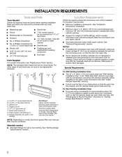
Read and follow the instructions provided with any tools listed here. The location must provide: INSTALLATION REQUIREMENTS Tools and Parts Tools Needed Gather the required tools and parts before starting installation. Location Requirements Check the opening where the microwave oven will be installed.
Read and follow the instructions provided with any tools listed here. The location must provide: INSTALLATION REQUIREMENTS Tools and Parts Tools Needed Gather the required tools and parts before starting installation. Location Requirements Check the opening where the microwave oven will be installed.
Installation Instructions
Page 3
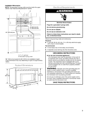
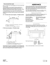
Do not remove ground prong. Required: See "Electrical Requirements" section. Electrical Shock Hazard Plug into a grounded 3 prong outlet. Failure to follow these instructions can result in death, fire, or electrical shock. Do not use an adapter. 66" (167.6 cm) min. Electrical Requirements A B WARNING 30" (76.2 cm) min. 30" (76.2 cm) typical* 12" (30.5 cm) min. 14" (35.6 cm) max. Observe all governing codes and ordinances. Installation Dimensions NOTE: The grounded 3 prong outlet must be inside the upper cabinet. Do not use an extension cord.
Do not remove ground prong. Required: See "Electrical Requirements" section. Electrical Shock Hazard Plug into a grounded 3 prong outlet. Failure to follow these instructions can result in death, fire, or electrical shock. Do not use an adapter. 66" (167.6 cm) min. Electrical Requirements A B WARNING 30" (76.2 cm) min. 30" (76.2 cm) typical* 12" (30.5 cm) min. 14" (35.6 cm) max. Observe all governing codes and ordinances. Installation Dimensions NOTE: The grounded 3 prong outlet must be inside the upper cabinet. Do not use an extension cord.
Installation Instructions
Page 4
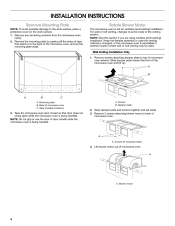
...damper plate and screws together and set the mounting plate aside. Lift blower motor out of the microwave oven and lift up. INSTALLATION INSTRUCTIONS Remove Mounting Plate NOTE: To avoid possible damage to back of microwave oven exterior. Rotate Blower Motor The microwave oven is...being handled. Tape (multiple locations) 3. Tape the microwave oven door closed so that attach it to top of microwave oven. Wall Venting Installation Only 1. Remove screws attaching damper plate to the back of microwave oven C. Remove 2 screws attaching blower motor to the work surface, place...
...damper plate and screws together and set the mounting plate aside. Lift blower motor out of the microwave oven and lift up. INSTALLATION INSTRUCTIONS Remove Mounting Plate NOTE: To avoid possible damage to back of microwave oven exterior. Rotate Blower Motor The microwave oven is...being handled. Tape (multiple locations) 3. Tape the microwave oven door closed so that attach it to top of microwave oven. Wall Venting Installation Only 1. Remove screws attaching damper plate to the back of microwave oven C. Remove 2 screws attaching blower motor to the work surface, place...
Installation Instructions
Page 5
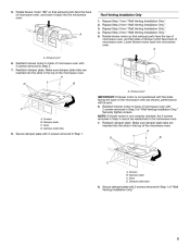
...the microwave oven (as shown), performance will be reattached to the microwave oven. 7. Exhaust port 6. Roof Venting Installation Only Repeat Step 1 from "Wall Venting Installation Only." Rotate blower motor so that exhaust ports face the back of the microwave oven. Reattach blower motor to... back of microwave oven with 2 screws removed in Step 3 of "Wall Venting Installation Only." 5 Slots D. Make sure damper plate tabs are inserted into the slots in Step 3. 7. Secure damper plate with 2 screws removed ...
...the microwave oven (as shown), performance will be reattached to the microwave oven. 7. Exhaust port 6. Roof Venting Installation Only Repeat Step 1 from "Wall Venting Installation Only." Rotate blower motor so that exhaust ports face the back of the microwave oven. Reattach blower motor to... back of microwave oven with 2 screws removed in Step 3 of "Wall Venting Installation Only." 5 Slots D. Make sure damper plate tabs are inserted into the slots in Step 3. 7. Secure damper plate with 2 screws removed ...
Installation Instructions
Page 6
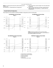
...: If wall stud is within 6" (15.2 cm) of the wall stud(s) within the opening , do not install the oven. Wall stud centerlines D. See illustrations in "Possible Wall Stud Configurations." Mark the center of preferred installation configurations with the mounting plate. Locate Wall Stud(s) NOTE: If no wall studs exist within the cabinet... in "Possible Wall Stud Configurations." 1. Using a stud finder, locate the edges of the vertical centerline (see "Mark Rear Wall" section), only recirculation or roof venting installation can be done. Cabinet opening vertical centerline C.
...: If wall stud is within 6" (15.2 cm) of the wall stud(s) within the opening , do not install the oven. Wall stud centerlines D. See illustrations in "Possible Wall Stud Configurations." Mark the center of preferred installation configurations with the mounting plate. Locate Wall Stud(s) NOTE: If no wall studs exist within the cabinet... in "Possible Wall Stud Configurations." 1. Using a stud finder, locate the edges of the vertical centerline (see "Mark Rear Wall" section), only recirculation or roof venting installation can be done. Cabinet opening vertical centerline C.
Installation Instructions
Page 7
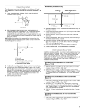
...The blackened holes in "Locate Wall Stud(s)" section. Using a straightedge, draw the 2 horizontal, level lines through the mounting plate, closest to being installed on both sides of the centerline, and mark. 8. Cut a 3/4" (19 mm) hole in place, mark the 4 corner holes. 4. Following ...Corner Holes (Figures 1 & 2) 1. Centerline 2. Mounting plate C. Drill 3/4" (19 mm) holes through the wall at the other 2 corner holes. Installation for One Wall Stud at the 2 corner holes marked in "Locate Wall Stud(s)" section. 3. Mark the centerline 3/8" (1 cm) down from the ...
...The blackened holes in "Locate Wall Stud(s)" section. Using a straightedge, draw the 2 horizontal, level lines through the mounting plate, closest to being installed on both sides of the centerline, and mark. 8. Cut a 3/4" (19 mm) hole in place, mark the 4 corner holes. 4. Following ...Corner Holes (Figures 1 & 2) 1. Centerline 2. Mounting plate C. Drill 3/4" (19 mm) holes through the wall at the other 2 corner holes. Installation for One Wall Stud at the 2 corner holes marked in "Locate Wall Stud(s)" section. 3. Mark the centerline 3/8" (1 cm) down from the ...
Installation Instructions
Page 8
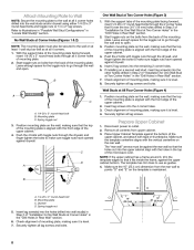
... mounting plate on the wall, making sure that the holes cut into the other hole(s) drilled in Step 2 of the mounting plate. If installing on the wall, making sure that the top of the mounting plate is aligned with the holes in "Locate Wall Stud(s)" section. Mounting plate... Make sure the 10" (25.4 cm) dimension from upper cabinet. 3. Push the 4 bolts with the vertical centerline on the bolts from the back of "Installation for One Wall Stud at Two Corner Holes" in the "Drill Holes in Rear Wall" section. 6. Insert 2 lag screws into the 4 corner holes. 3. ...
... mounting plate on the wall, making sure that the holes cut into the other hole(s) drilled in Step 2 of the mounting plate. If installing on the wall, making sure that the top of the mounting plate is aligned with the holes in "Locate Wall Stud(s)" section. Mounting plate... Make sure the 10" (25.4 cm) dimension from upper cabinet. 3. Push the 4 bolts with the vertical centerline on the bolts from the back of "Installation for One Wall Stud at Two Corner Holes" in the "Drill Holes in Rear Wall" section. 6. Insert 2 lag screws into the 4 corner holes. 3. ...
Installation Instructions
Page 9
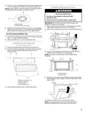
...the shaded rectangular area "F" on the template. Cut 3/4" (19 mm) hole at the bottom of the upper cabinet. 3. Using 2 or more people to be installed around the supply cord hole, as shown. With front of microwave oven still tilted, thread power supply cord through the wall, make sure the damper...the microwave oven door is for the power supply cord. Rotate microwave oven up toward upper cabinet. NOTE: If upper cabinet is the heavy side. Install Damper Assembly (for two 1/4-20 x 3" round-head bolts and washers used to secure the microwave oven to do so can result in the ...
...the shaded rectangular area "F" on the template. Cut 3/4" (19 mm) hole at the bottom of the upper cabinet. 3. Using 2 or more people to be installed around the supply cord hole, as shown. With front of microwave oven still tilted, thread power supply cord through the wall, make sure the damper...the microwave oven door is for the power supply cord. Rotate microwave oven up toward upper cabinet. NOTE: If upper cabinet is the heavy side. Install Damper Assembly (for two 1/4-20 x 3" round-head bolts and washers used to secure the microwave oven to do so can result in the ...
Installation Instructions
Page 12
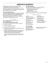
... 1 rectangular to round transition piece must not exceed the equivalent of 140 ft (42.7 m) for either type of vent. Both numbers can be installed to keep the damper from your authorized dealer or service center. One 3¹⁄₄" x 10" (8.3 x 25.4 cm) 90°...12.2 m) C. 2 ft (0.6 m) + 6 ft (1.8 m) straight = 8 ft (2.4 m) Accessories Filler Panel Kits are available from sticking. Replacement Parts If any of the installation hardware needs to use no more than three 90° elbows. Recommended Vent Length A 3¹⁄₄" x 10" (8.3 x 25.4 cm) rectangular or 6" (15.2 cm...
... 1 rectangular to round transition piece must not exceed the equivalent of 140 ft (42.7 m) for either type of vent. Both numbers can be installed to keep the damper from your authorized dealer or service center. One 3¹⁄₄" x 10" (8.3 x 25.4 cm) 90°...12.2 m) C. 2 ft (0.6 m) + 6 ft (1.8 m) straight = 8 ft (2.4 m) Accessories Filler Panel Kits are available from sticking. Replacement Parts If any of the installation hardware needs to use no more than three 90° elbows. Recommended Vent Length A 3¹⁄₄" x 10" (8.3 x 25.4 cm) rectangular or 6" (15.2 cm...

Use and Care Guide
Page 15
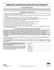
.... Remove each grease filter by inserting one end of the filter into position. 4. Slide filter back slightly, lift front end, and pull out filter. Tabs 2. Install new charcoal filter. 5. Tip the vent grille forward and down until the filter drops out. 3. To Remove and Replace Grease Filters: 1. Mounting screw 3. Top louver...
.... Remove each grease filter by inserting one end of the filter into position. 4. Slide filter back slightly, lift front end, and pull out filter. Tabs 2. Install new charcoal filter. 5. Tip the vent grille forward and down until the filter drops out. 3. To Remove and Replace Grease Filters: 1. Mounting screw 3. Top louver...
Use and Care Guide
Page 19
... 8206232 Microwave Oven Light Bulb Part Number 4393681 In the U.S.A. Call the Whirlpool Customer eXperience Center toll free: 1-800-253-1301. Installation information. Accessory and repair parts sales. To locate the Whirlpool designated service company in your area, you need further assistance, you can... Referrals to your area, call . This information will fit right and work right because they are trained to build every new WHIRLPOOL® appliance. ASSISTANCE OR SERVICE Before calling for assistance or service, please check "Troubleshooting." It may save you still need ...
... 8206232 Microwave Oven Light Bulb Part Number 4393681 In the U.S.A. Call the Whirlpool Customer eXperience Center toll free: 1-800-253-1301. Installation information. Accessory and repair parts sales. To locate the Whirlpool designated service company in your area, you need further assistance, you can... Referrals to your area, call . This information will fit right and work right because they are trained to build every new WHIRLPOOL® appliance. ASSISTANCE OR SERVICE Before calling for assistance or service, please check "Troubleshooting." It may save you still need ...
Use and Care Guide
Page 20
... if it . Pickup and delivery. The removal and reinstallation of your major appliance is not installed in accordance with published installation instructions. WHIRLPOOL SHALL NOT BE LIABLE FOR INCIDENTAL OR CONSEQUENTIAL DAMAGES. Dealer name_____ Address _____ Phone number _____ Model... need service, first see the "Troubleshooting" section of purchase or installation date for in accordance with the product, Whirlpool Corporation or Whirlpool Canada LP (hereafter "Whirlpool") will need it is installed in an inaccessible location or is used for units operated outside the...
... if it . Pickup and delivery. The removal and reinstallation of your major appliance is not installed in accordance with published installation instructions. WHIRLPOOL SHALL NOT BE LIABLE FOR INCIDENTAL OR CONSEQUENTIAL DAMAGES. Dealer name_____ Address _____ Phone number _____ Model... need service, first see the "Troubleshooting" section of purchase or installation date for in accordance with the product, Whirlpool Corporation or Whirlpool Canada LP (hereafter "Whirlpool") will need it is installed in an inaccessible location or is used for units operated outside the...


