
Installation Instructions
Page 3
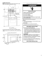
Electrical Requirements A B WARNING 30" (76.2 cm) min. 30" (76.2 cm) typical* 12" (30.5 cm) min. 14" (35.6 cm) max. Required: Do not remove ground prong. Observe all governing codes and ordinances. Do not use an extension cord. Electrical Shock Hazard Plug into a grounded 3 prong outlet. See "Electrical Requirements" section. Do not use an adapter. 66" (167.6 cm) min. Installation Dimensions NOTE: The grounded 3 prong outlet must be inside the upper cabinet. Failure to follow these instructions can result in death, fire, or electrical shock.
Electrical Requirements A B WARNING 30" (76.2 cm) min. 30" (76.2 cm) typical* 12" (30.5 cm) min. 14" (35.6 cm) max. Required: Do not remove ground prong. Observe all governing codes and ordinances. Do not use an extension cord. Electrical Shock Hazard Plug into a grounded 3 prong outlet. See "Electrical Requirements" section. Do not use an adapter. 66" (167.6 cm) min. Installation Dimensions NOTE: The grounded 3 prong outlet must be inside the upper cabinet. Failure to follow these instructions can result in death, fire, or electrical shock.
Installation Instructions
Page 8
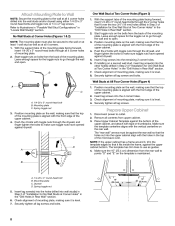
... the upper cabinet bottom. B Wall Studs at Two Corner Holes (Figure 3) 1. A. 1/4-20 x 3" round-head bolt B. Remove all lag screws. Make sure the 10" (25.4 cm) dimension from the rear wall to open . Check alignment of mounting plate. 2. With the support tabs of the mounting plate facing forward, insert 1/4-20 x 3" round-head...
... the upper cabinet bottom. B Wall Studs at Two Corner Holes (Figure 3) 1. A. 1/4-20 x 3" round-head bolt B. Remove all lag screws. Make sure the 10" (25.4 cm) dimension from the rear wall to open . Check alignment of mounting plate. 2. With the support tabs of the mounting plate facing forward, insert 1/4-20 x 3" round-head...

