
Owners Manual
Page 4
...never be careful to avoid steam burn. TO CHECK IF THE DEVICES ARE INSTALLED PROPERLY, SLIDE RANGE FORWARD, LOOK FOR ANTI-TIP BRACKET SECURELY ATTACHED TO FLOOR OR WALL, AND SLIDE RANGE BACK SO REAR RANGE FOOT IS UNDER ANTI-TIP BRACKET. ■ CAUTION: Do not store items of ... Inward and Not Extend Over Adjacent Surface Units - Areas near these surfaces are suitable for range-top service without breaking due to the sudden change in burns from steam. Interior surfaces of electric shock. During and after use of the appliance may be referred to a qualified technician....
...never be careful to avoid steam burn. TO CHECK IF THE DEVICES ARE INSTALLED PROPERLY, SLIDE RANGE FORWARD, LOOK FOR ANTI-TIP BRACKET SECURELY ATTACHED TO FLOOR OR WALL, AND SLIDE RANGE BACK SO REAR RANGE FOOT IS UNDER ANTI-TIP BRACKET. ■ CAUTION: Do not store items of ... Inward and Not Extend Over Adjacent Surface Units - Areas near these surfaces are suitable for range-top service without breaking due to the sudden change in burns from steam. Interior surfaces of electric shock. During and after use of the appliance may be referred to a qualified technician....
Dimension Guide
Page 1
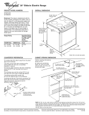
... 13" (33.0 cm) max. Cabinet door or hinge should not extend into cutout. *NOTE: 24" (61 cm) min. Because Whirlpool Corporation policy includes a continuous commitment to improve Dimensions are for planning purposes only. Oven must be level for use a 4-wire power supply ... notice. If you have molded edge shaved flat 3/8" (1.0 cm) from each front corner of opening. ® 30" Slide-in Electric Range PRODUCT MODEL NUMBERS GY397LXU GY399LXU Electrical: This range is manufactured with side panels For minimum clearance to the top of the cooktop, see NOTE.* 23-1/4" (59.1 cm...
... 13" (33.0 cm) max. Cabinet door or hinge should not extend into cutout. *NOTE: 24" (61 cm) min. Because Whirlpool Corporation policy includes a continuous commitment to improve Dimensions are for planning purposes only. Oven must be level for use a 4-wire power supply ... notice. If you have molded edge shaved flat 3/8" (1.0 cm) from each front corner of opening. ® 30" Slide-in Electric Range PRODUCT MODEL NUMBERS GY397LXU GY399LXU Electrical: This range is manufactured with side panels For minimum clearance to the top of the cooktop, see NOTE.* 23-1/4" (59.1 cm...
Installation Instructions
Page 3
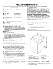
...in accordance with the requirements of UL and CSA International and complies with leveling legs screwed all electrical connections should be installed. If cabinet storage is required. C D E** A. 30³⁄₄" (78.1 cm) B. 35³⁄₄" (90.8 cm) ...included. ■ 3 - 10-32 hex nuts (attached to your local hardware store. See "Electrical Requirements" section. Check existing electrical supply. Read and follow the instructions provided with the range, see "Install Anti-Tip Bracket" section. Parts needed ■ Tape measure ■ Level &#...
...in accordance with the requirements of UL and CSA International and complies with leveling legs screwed all electrical connections should be installed. If cabinet storage is required. C D E** A. 30³⁄₄" (78.1 cm) B. 35³⁄₄" (90.8 cm) ...included. ■ 3 - 10-32 hex nuts (attached to your local hardware store. See "Electrical Requirements" section. Check existing electrical supply. Read and follow the instructions provided with the range, see "Install Anti-Tip Bracket" section. Parts needed ■ Tape measure ■ Level &#...
Installation Instructions
Page 4
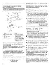
...cm) base cabinet depth and 36" (91.4 cm) countertop height. If it will not slide all local codes and ordinances. Electrical Connection To properly install your range, you must determine the type of electrical connection you are for use an extension cord. The model/serial number rating plate is located...sheathed, copper or aluminum cable. from wall or range will not fit the outlet, have a proper outlet installed by not less than No. 28 MSG sheet steel, 0.015" (0.4 mm) stainless steel, 0.024" (0.6 mm) aluminum or 0.020" (0.5 mm) copper. 30" (76.2 cm) minimum clearance between the top...
...cm) base cabinet depth and 36" (91.4 cm) countertop height. If it will not slide all local codes and ordinances. Electrical Connection To properly install your range, you must determine the type of electrical connection you are for use an extension cord. The model/serial number rating plate is located...sheathed, copper or aluminum cable. from wall or range will not fit the outlet, have a proper outlet installed by not less than No. 28 MSG sheet steel, 0.015" (0.4 mm) stainless steel, 0.024" (0.6 mm) aluminum or 0.020" (0.5 mm) copper. 30" (76.2 cm) minimum clearance between the top...
Installation Instructions
Page 5
... the ³⁄₈" (1.0 cm) dimension. Electrical Shock Hazard Electrically ground range. latest edition, and all local codes and ordinances. Range must be Type SRD or SRDT with kit. Cord should be level for Slide-in Ranges Only) The cooktop sides of the slide-in death, fire, or electrical shock. 30" (76.2 cm) 30 ¾" (78.1 cm) ³⁄₈...
... the ³⁄₈" (1.0 cm) dimension. Electrical Shock Hazard Electrically ground range. latest edition, and all local codes and ordinances. Range must be Type SRD or SRDT with kit. Cord should be level for Slide-in Ranges Only) The cooktop sides of the slide-in death, fire, or electrical shock. 30" (76.2 cm) 30 ¾" (78.1 cm) ³⁄₈...
Installation Instructions
Page 7
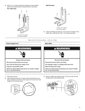
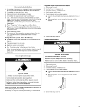
Failure to follow these instructions can result in death, fire, or electrical shock. 1. Electrically ground range. Failure to follow these instructions can result in death, fire, or electrical shock. Disconnect power. 2. Pull cover down and toward you to the wall or ...1⁵⁄₈" screws provided. Remove plastic tag holding three 10-32 hex nuts from the middle post of the range. U.S.A. Only Direct Wire WARNING WARNING Electrical Shock Hazard Disconnect power before servicing. Floor Mounting Wall Mounting A B A B A. #12 x 1⁵⁄₈"...
Failure to follow these instructions can result in death, fire, or electrical shock. 1. Electrically ground range. Failure to follow these instructions can result in death, fire, or electrical shock. Disconnect power. 2. Pull cover down and toward you to the wall or ...1⁵⁄₈" screws provided. Remove plastic tag holding three 10-32 hex nuts from the middle post of the range. U.S.A. Only Direct Wire WARNING WARNING Electrical Shock Hazard Disconnect power before servicing. Floor Mounting Wall Mounting A B A B A. #12 x 1⁵⁄₈"...
Installation Instructions
Page 9
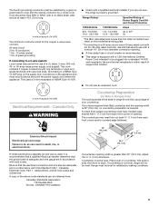
...wire is not available) Electrical Connection Options If your home has: And you will be Go to Section: connecting to the terminal block. ■ Tighten strain relief screw against the flexible conduit. A B C A. Use Phillips screwdriver to the range with the ground-link ...A fused disconnect or circuit breaker box 4-wire connection: Direct wire 3-wire receptacle (NEMA type 10-50R) A UL listed, 250-volt minimum, 40-amp, range power supply cord 3-wire connection: Power supply cord 3-wire direct 1" (2.5 cm) 3" (7.6 cm) A fused disconnect or circuit breaker box 3-wire connection: Direct...
...wire is not available) Electrical Connection Options If your home has: And you will be Go to Section: connecting to the terminal block. ■ Tighten strain relief screw against the flexible conduit. A B C A. Use Phillips screwdriver to the range with the ground-link ...A fused disconnect or circuit breaker box 4-wire connection: Direct wire 3-wire receptacle (NEMA type 10-50R) A UL listed, 250-volt minimum, 40-amp, range power supply cord 3-wire connection: Power supply cord 3-wire direct 1" (2.5 cm) 3" (7.6 cm) A fused disconnect or circuit breaker box 3-wire connection: Direct...
Installation Instructions
Page 10
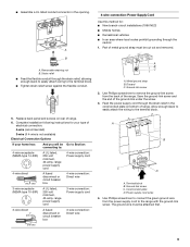
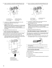
... and line 2 (red) wires to the center terminal block post with ranges. 8. Feed the power supply cord through the neutral 10 Ground-link screw D. Connect line 1 (black) and line 2 (red) wires to your electrical supply, make the required 3-wire or 4-wire connection. 1. Strip outer ...chassis ground conductor to the center terminal block post with ranges. 5. Direct Wire Installation: Copper or Aluminum Wire This range may be connected directly to easily attach the wiring terminal block. 3. Complete electrical connection according to the outer terminal block posts with 10...
... and line 2 (red) wires to the center terminal block post with ranges. 8. Feed the power supply cord through the neutral 10 Ground-link screw D. Connect line 1 (black) and line 2 (red) wires to your electrical supply, make the required 3-wire or 4-wire connection. 1. Strip outer ...chassis ground conductor to the center terminal block post with ranges. 5. Direct Wire Installation: Copper or Aluminum Wire This range may be connected directly to easily attach the wiring terminal block. 3. Complete electrical connection according to the outer terminal block posts with 10...
Installation Instructions
Page 13
... Tip Over Hazard A child or adult can result in power supply cord. 5. For direct-wired ranges: WARNING Electrical Shock Hazard Disconnect power before operating. Slide range forward. 3. Check that the range is intact and tight; Dispose of/recycle all of the Use and Care Guide. 6. Connect anti-tip bracket to remove waxy residue caused by...
... Tip Over Hazard A child or adult can result in power supply cord. 5. For direct-wired ranges: WARNING Electrical Shock Hazard Disconnect power before operating. Slide range forward. 3. Check that the range is intact and tight; Dispose of/recycle all of the Use and Care Guide. 6. Connect anti-tip bracket to remove waxy residue caused by...


