
Use & Care Guide
Page 1
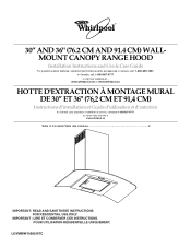
... et d'entretien Au Canada, pour assistance, installation ou service, composer 1-800-807-6777 ou visiter notre site web à www.whirlpool.ca Table of Contents/Table des matières 2 IMPORTANT: READ AND SAVE THESE INSTRUCTIONS. POUR UTILISATION RÉSIDENTIELLE UNIQUEMENT. LI3YMB.../W10292167C ® 30" AND 36" (76.2 CM AND 91.4 CM) WALLMOUNT CANOPY RANGE HOOD Installation Instructions and Use & Care Guide For questions about features, operation/performance parts, accessories or service, call : 1-800-807-6777 or...
... et d'entretien Au Canada, pour assistance, installation ou service, composer 1-800-807-6777 ou visiter notre site web à www.whirlpool.ca Table of Contents/Table des matières 2 IMPORTANT: READ AND SAVE THESE INSTRUCTIONS. POUR UTILISATION RÉSIDENTIELLE UNIQUEMENT. LI3YMB.../W10292167C ® 30" AND 36" (76.2 CM AND 91.4 CM) WALLMOUNT CANOPY RANGE HOOD Installation Instructions and Use & Care Guide For questions about features, operation/performance parts, accessories or service, call : 1-800-807-6777 or...
Use & Care Guide
Page 2
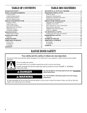
... Venting Requirements 5 Electrical Requirements 6 INSTALLATION INSTRUCTIONS 7 Prepare Location 7 Install Range Hood 8 Connect Vent System 8 Make Electrical Connection 9 Install Vent Covers 9 Complete Installation 10 RANGE HOOD USE 10 Range Hood Controls 10 RANGE HOOD CARE 11 Cleaning 11 WIRING DIAGRAM 12 ASSISTANCE OR SERVICE 13 In the U.S.A ... 24 SCHÉMA DE CÂBLAGE 26 ASSISTANCE OU SERVICE 27 Au Canada 27 Accessoires 27 GARANTIE 27 RANGE HOOD SAFETY Your safety and the safety of injury, and tell you don't immediately follow instructions. We have provided many ...
... Venting Requirements 5 Electrical Requirements 6 INSTALLATION INSTRUCTIONS 7 Prepare Location 7 Install Range Hood 8 Connect Vent System 8 Make Electrical Connection 9 Install Vent Covers 9 Complete Installation 10 RANGE HOOD USE 10 Range Hood Controls 10 RANGE HOOD CARE 11 Cleaning 11 WIRING DIAGRAM 12 ASSISTANCE OR SERVICE 13 In the U.S.A ... 24 SCHÉMA DE CÂBLAGE 26 ASSISTANCE OU SERVICE 27 Au Canada 27 Accessoires 27 GARANTIE 27 RANGE HOOD SAFETY Your safety and the safety of injury, and tell you don't immediately follow instructions. We have provided many ...

Use & Care Guide
Page 3
... IN THE EVENT OF A RANGE TOP GREASE FIRE, OBSERVE THE FOLLOWING:a ■ SMOTHER FLAMES with a close fitting lid, cookie sheet, or metal tray, then turn hood ON when cooking at high settings. Do not use only. The fire is small and contained in accordance with all applicable codes and standards, including...
... IN THE EVENT OF A RANGE TOP GREASE FIRE, OBSERVE THE FOLLOWING:a ■ SMOTHER FLAMES with a close fitting lid, cookie sheet, or metal tray, then turn hood ON when cooking at high settings. Do not use only. The fire is small and contained in accordance with all applicable codes and standards, including...

Use & Care Guide
Page 4
...also need : ■ Recirculation Kit Part Number W10294733 for non-vented (recirculating) installations only. round metal vent duct - Canopy hood location should be away from packages. It is the installer's responsibility to comply with any tools listed here. All openings in "... the roof or wall. length required is required. The model/serial rating plate is a registered trademark of the vent hood. The canopy hood is available from your dealer or an authorized parts distributor. For non-vented (recirculating) Installation see "Non-vented (recirculating...
...also need : ■ Recirculation Kit Part Number W10294733 for non-vented (recirculating) installations only. round metal vent duct - Canopy hood location should be away from packages. It is the installer's responsibility to comply with any tools listed here. All openings in "... the roof or wall. length required is required. The model/serial rating plate is a registered trademark of the vent hood. The canopy hood is available from your dealer or an authorized parts distributor. For non-vented (recirculating) Installation see "Non-vented (recirculating...
Use & Care Guide
Page 5
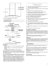
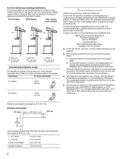
...(76.2 cm) or 36" (91.4 cm) "X" bottom of straight vent between the bottom of the vent should be installed immediately above the hood. 5 Venting Requirements (vented models only) ■ Vent system must have a damper. Cold Weather Installations An additional back draft damper should be ...installed to provide efficient performance. The break should be uniform. Venting Methods This canopy hood is needed . The hood exhaust opening is available from locale to minimize conduction of outside temperatures as possible to seal exterior wall or roof ...
...(76.2 cm) or 36" (91.4 cm) "X" bottom of straight vent between the bottom of the vent should be installed immediately above the hood. 5 Venting Requirements (vented models only) ■ Vent system must have a damper. Cold Weather Installations An additional back draft damper should be ...installed to provide efficient performance. The break should be uniform. Venting Methods This canopy hood is needed . The hood exhaust opening is available from locale to minimize conduction of outside temperatures as possible to seal exterior wall or roof ...
Use & Care Guide
Page 6
...permit and a separate ground wire is used, it is not possible to vent cooking fumes and vapors to the outside, the hood can be used in the system. Aluminum/copper connection must conform with local codes and industry accepted wiring practices. ■ Wire ... 45° elbow 2.5 ft (0.8 m) 90° elbow 5.0 ft (1.5 m) Electrical Requirements Observe all local codes and ordinances. Connect a section of the range hood. ■ Wire sizes must conform with National Electrical Code, ANSI/NFPA 70 (latest edition), or CSA Standards C22.1-94, Canadian Electrical Code, Part 1 and C22...
...permit and a separate ground wire is used, it is not possible to vent cooking fumes and vapors to the outside, the hood can be used in the system. Aluminum/copper connection must conform with local codes and industry accepted wiring practices. ■ Wire ... 45° elbow 2.5 ft (0.8 m) 90° elbow 5.0 ft (1.5 m) Electrical Requirements Observe all local codes and ordinances. Connect a section of the range hood. ■ Wire sizes must conform with National Electrical Code, ANSI/NFPA 70 (latest edition), or CSA Standards C22.1-94, Canadian Electrical Code, Part 1 and C22...

Use & Care Guide
Page 7
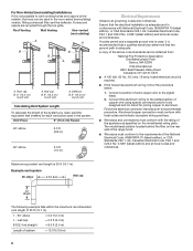
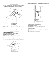
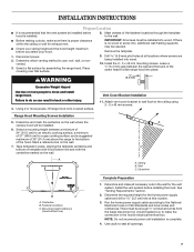
... head to screw into place. Wall C. Fastener locations C. Determine and make all openings. 7 Install the vent system before you select your hood. Determine the required height for the home power supply cable and drill a 1¼" (3.2 cm) hole at all locations where screws are... clearance within the ceiling or wall for the vent system. Remove the template. 1. Disconnect power. 2. Place covering over that the vent system be installed before hood is complete. 4. Install the 2 - 5 x 45 mm mounting screws. Leave a ¹⁄₄" (6.4 mm) gap between a minimum of 24" (...
... head to screw into place. Wall C. Fastener locations C. Determine and make all openings. 7 Install the vent system before you select your hood. Determine the required height for the home power supply cable and drill a 1¼" (3.2 cm) hole at all locations where screws are... clearance within the ceiling or wall for the vent system. Remove the template. 1. Disconnect power. 2. Place covering over that the vent system be installed before hood is complete. 4. Install the 2 - 5 x 45 mm mounting screws. Leave a ¹⁄₄" (6.4 mm) gap between a minimum of 24" (...
Use & Care Guide
Page 8
...with the duct cover bracket with 4 assembly screws. 8. Reassemble the air deflector to the bottom of the hood outlet. Air deflector C. C B 2. Measure from the hood. 7. Remove the grease filter. Seal connection with the Recirculation Kit. assembly screws provided with clamps. 3.... Air deflector B. X = length to the measured size (X). 4. Vent duct E. Slide the duct onto the bottom of hood. Assembly screws B. See "Range Hood Care" section. 3. Connect Vent System For vented installations only: 1. A. A B C A. Check that backdraft dampers work properly....
...with the duct cover bracket with 4 assembly screws. 8. Reassemble the air deflector to the bottom of the hood outlet. Air deflector C. C B 2. Measure from the hood. 7. Remove the grease filter. Seal connection with the Recirculation Kit. assembly screws provided with clamps. 3.... Air deflector B. X = length to the measured size (X). 4. Vent duct E. Slide the duct onto the bottom of hood. Assembly screws B. See "Range Hood Care" section. 3. Connect Vent System For vented installations only: 1. A. A B C A. Check that backdraft dampers work properly....

Use & Care Guide
Page 9
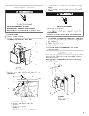
... Disconnect power before operating. Replace all light bulbs are secure in terminal box using both upper and lower vent covers, push lower cover down onto hood and lift upper cover to ceiling and install with two 4 x 8 mm screws. Failure to do so can result in death or electrical shock. 1. Remove terminal...
... Disconnect power before operating. Replace all light bulbs are secure in terminal box using both upper and lower vent covers, push lower cover down onto hood and lift upper cover to ceiling and install with two 4 x 8 mm screws. Failure to do so can result in death or electrical shock. 1. Remove terminal...
Use & Care Guide
Page 10
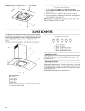
...Lamp cover G. The speed can be changed anytime during fan operation by pressing the desired blower speed button. See the "Range Hood Use" section. Blower speed minimum button D. Blower speed maximum button C Operating the light The On/Off light button controls both ...the operation of lamps may vary) H. Duct cover holes B. Grease filter F. Incandescent lamp (position and number of the range hood blower and light. Complete Installation 1. Range Hood Controls A B C D E A. Secure the bottom of the canopy. For non-vented (recirculating) installations only, install ...
...Lamp cover G. The speed can be changed anytime during fan operation by pressing the desired blower speed button. See the "Range Hood Use" section. Blower speed minimum button D. Blower speed maximum button C Operating the light The On/Off light button controls both ...the operation of lamps may vary) H. Duct cover holes B. Grease filter F. Incandescent lamp (position and number of the range hood blower and light. Complete Installation 1. Range Hood Controls A B C D E A. Secure the bottom of the canopy. For non-vented (recirculating) installations only, install ...
Use & Care Guide
Page 11
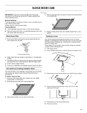
... Installation Filters: The charcoal filter is not washable. Remove metal grease filter from lamp cover. Reconnect power. 11 A Turn off the range hood and allow the lamp to handle bulb. To avoid damage or decreasing the life of metal filter. 5. Spring release handle 2. Push in... this section. Push up to remove screw from range hood. Replace with a new 120 volt, 40 watt maximum E-12 bulb. 3. Replace metal grease filter. Metal Grease Filter: Replacing a Lamp 1. ...
... Installation Filters: The charcoal filter is not washable. Remove metal grease filter from lamp cover. Reconnect power. 11 A Turn off the range hood and allow the lamp to handle bulb. To avoid damage or decreasing the life of metal filter. 5. Spring release handle 2. Push in... this section. Push up to remove screw from range hood. Replace with a new 120 volt, 40 watt maximum E-12 bulb. 3. Replace metal grease filter. Metal Grease Filter: Replacing a Lamp 1. ...

Installation Guide
Page 1
...utilisation et d'entretien Au Canada, pour assistance, installation ou service, composer 1-800-807-6777 ou visiter notre site web à www.whirlpool.ca Table of Contents/Table des matières 2 IMPORTANT: READ AND SAVE THESE INSTRUCTIONS. LI3YMB/W10292167C FOR RESIDENTIAL USE ONLY. ®...; 30" AND 36" (76.2 CM AND 91.4 CM) WALLMOUNT CANOPY RANGE HOOD Installation Instructions and Use & Care Guide For questions about features, operation/performance parts, accessories or service, call : 1-800-807-6777 or visit...
...utilisation et d'entretien Au Canada, pour assistance, installation ou service, composer 1-800-807-6777 ou visiter notre site web à www.whirlpool.ca Table of Contents/Table des matières 2 IMPORTANT: READ AND SAVE THESE INSTRUCTIONS. LI3YMB/W10292167C FOR RESIDENTIAL USE ONLY. ®...; 30" AND 36" (76.2 CM AND 91.4 CM) WALLMOUNT CANOPY RANGE HOOD Installation Instructions and Use & Care Guide For questions about features, operation/performance parts, accessories or service, call : 1-800-807-6777 or visit...

Installation Guide
Page 2
... Venting Requirements 5 Electrical Requirements 6 INSTALLATION INSTRUCTIONS 7 Prepare Location 7 Install Range Hood 8 Connect Vent System 8 Make Electrical Connection 9 Install Vent Covers 9 Complete Installation 10 RANGE HOOD USE 10 Range Hood Controls 10 RANGE HOOD CARE 11 Cleaning 11 WIRING DIAGRAM 12 ASSISTANCE OR SERVICE 13 In the U.S.A 13... 24 SCHÉMA DE CÂBLAGE 26 ASSISTANCE OU SERVICE 27 Au Canada 27 Accessoires 27 GARANTIE 27 RANGE HOOD SAFETY Your safety and the safety of injury, and tell you what the potential hazard is the safety alert symbol....
... Venting Requirements 5 Electrical Requirements 6 INSTALLATION INSTRUCTIONS 7 Prepare Location 7 Install Range Hood 8 Connect Vent System 8 Make Electrical Connection 9 Install Vent Covers 9 Complete Installation 10 RANGE HOOD USE 10 Range Hood Controls 10 RANGE HOOD CARE 11 Cleaning 11 WIRING DIAGRAM 12 ASSISTANCE OR SERVICE 13 In the U.S.A 13... 24 SCHÉMA DE CÂBLAGE 26 ASSISTANCE OU SERVICE 27 Au Canada 27 Accessoires 27 GARANTIE 27 RANGE HOOD SAFETY Your safety and the safety of injury, and tell you what the potential hazard is the safety alert symbol....

Installation Guide
Page 3
... IN THE EVENT OF A RANGE TOP GREASE FIRE, OBSERVE THE FOLLOWING:a ■ SMOTHER FLAMES with a close fitting lid, cookie sheet, or metal tray, then turn hood ON when cooking at high heat or when flambeing food (i.e. BE CAREFUL TO PREVENT BURNS. The fire department is needed for the size of fire...
... IN THE EVENT OF A RANGE TOP GREASE FIRE, OBSERVE THE FOLLOWING:a ■ SMOTHER FLAMES with a close fitting lid, cookie sheet, or metal tray, then turn hood ON when cooking at high heat or when flambeing food (i.e. BE CAREFUL TO PREVENT BURNS. The fire department is needed for the size of fire...
Installation Guide
Page 4
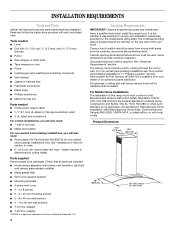
...All openings in "Prepare Location" section. INSTALLATION REQUIREMENTS Tools and Parts Gather the required tools and parts before starting installation. Canopy hood location should be away from packages. Parts supplied Remove parts from strong draft areas, such as windows, doors and strong heating ...;" (27.6 cm) 13 33.5 cm) 20" (50.8 cm) 30" (76.2 cm) or 36" (91.4 cm) The canopy hood is a registered trademark of Acument Intellectual Properties, LLC 4 Location Requirements IMPORTANT: Observe all parts are shown must conform to the Manufactured Home Construction Safety...
...All openings in "Prepare Location" section. INSTALLATION REQUIREMENTS Tools and Parts Gather the required tools and parts before starting installation. Canopy hood location should be away from packages. Parts supplied Remove parts from strong draft areas, such as windows, doors and strong heating ...;" (27.6 cm) 13 33.5 cm) 20" (50.8 cm) 30" (76.2 cm) or 36" (91.4 cm) The canopy hood is a registered trademark of Acument Intellectual Properties, LLC 4 Location Requirements IMPORTANT: Observe all parts are shown must conform to the Manufactured Home Construction Safety...

Installation Guide
Page 5
... higher ceilings, a Stainless Steel Chimney Extension Kit Part Number W10294735 is recommended. The chimney extension replaces the upper chimney shipped with the range hood. ■ Use caulking to minimize backward cold air flow and a thermal break should be on the distance "X" between 7' 4" (2.25... m) and 9' 9" (2.97 m) with the vent slots showing. Cold Weather Installations An additional back draft damper should be installed immediately above the hood. 5 Makeup Air Local building codes may be installed to seal exterior wall or roof opening is needed . A 6" (15.2 cm) round vent...
... higher ceilings, a Stainless Steel Chimney Extension Kit Part Number W10294735 is recommended. The chimney extension replaces the upper chimney shipped with the range hood. ■ Use caulking to minimize backward cold air flow and a thermal break should be on the distance "X" between 7' 4" (2.25... m) and 9' 9" (2.97 m) with the vent slots showing. Cold Weather Installations An additional back draft damper should be installed immediately above the hood. 5 Makeup Air Local building codes may be installed to seal exterior wall or roof opening is needed . A 6" (15.2 cm) round vent...
Installation Guide
Page 6
... System Length To calculate the length of the system you need, add the equivalent feet (meters) for joining copper to the outside, the hood can be used in the system. Connect the aluminum wiring to the added section of copper wire using special connectors and/or tools designed and... UL listed for each vent piece used in conformance with the rating of the range hood. ■ Wire sizes must conform with National Electrical Code, ANSI/NFPA 70 (latest edition), or CSA Standards C22.1-94, Canadian Electrical Code, Part 1 ...
... System Length To calculate the length of the system you need, add the equivalent feet (meters) for joining copper to the outside, the hood can be used in the system. Connect the aluminum wiring to the added section of copper wire using special connectors and/or tools designed and... UL listed for each vent piece used in conformance with the rating of the range hood. ■ Wire sizes must conform with National Electrical Code, ANSI/NFPA 70 (latest edition), or CSA Standards C22.1-94, Canadian Electrical Code, Part 1 ...
Installation Guide
Page 7
.... 6. Use caulk to the ceiling using 2 - 5 x 45 mm screws. Select a flat surface for the vent system. Range Hood Mounting Screws Installation 5. Disconnect power. 2. Attach vent cover bracket to wall flush to seal all openings. 7 Ceiling B. Centerline Vertical Centerline... HorizontalLine REAR W ALL M OUNTING TEM PLATE CL ALIGN BOTTOM EDGE W ITH PENCILLINE INDICATING BOTTOM OFTHE HOOD Installation Height B C A. Centerline B. Determine the required height for the home power supply cable and drill a 1¼" (3.2...
.... 6. Use caulk to the ceiling using 2 - 5 x 45 mm screws. Select a flat surface for the vent system. Range Hood Mounting Screws Installation 5. Disconnect power. 2. Attach vent cover bracket to wall flush to seal all openings. 7 Ceiling B. Centerline Vertical Centerline... HorizontalLine REAR W ALL M OUNTING TEM PLATE CL ALIGN BOTTOM EDGE W ITH PENCILLINE INDICATING BOTTOM OFTHE HOOD Installation Height B C A. Centerline B. Determine the required height for the home power supply cable and drill a 1¼" (3.2...

Installation Guide
Page 8
...the duct cover bracket with the Recirculation Kit. Cut the duct to cut vent duct D. A B C A. C B 2. Measure from the hood. 7. See "Range Hood Care" section. 3. Remove the air deflector. 5. Install 2 - 5 x 45 mm lower mounting screws and tighten. Connect Vent System For ... installation only: 1. Air deflector C. Check that backdraft dampers work properly. A. Assembly screws B. Using 2 or more people, hang range hood on 2 mounting screws through the mounting slots on back of the air deflector. 6. assembly screws provided with 4 - Vent clamp C. ...
...the duct cover bracket with the Recirculation Kit. Cut the duct to cut vent duct D. A B C A. C B 2. Measure from the hood. 7. See "Range Hood Care" section. 3. Remove the air deflector. 5. Install 2 - 5 x 45 mm lower mounting screws and tighten. Connect Vent System For ... installation only: 1. Air deflector C. Check that backdraft dampers work properly. A. Assembly screws B. Using 2 or more people, hang range hood on 2 mounting screws through the mounting slots on back of the air deflector. 6. assembly screws provided with 4 - Vent clamp C. ...
Installation Guide
Page 9
... from home power supply to green and yellow ground wire in terminal box using both upper and lower vent covers, push lower cover down onto hood and lift upper cover to hide slots. B A C C D E F A. UL listed or CSA approved strain relief C. Green (or bare) and yellow-green ground wires...
... from home power supply to green and yellow ground wire in terminal box using both upper and lower vent covers, push lower cover down onto hood and lift upper cover to hide slots. B A C C D E F A. UL listed or CSA approved strain relief C. Green (or bare) and yellow-green ground wires...


