Owners Manual
Page 2
... alert symbol and either the word "DANGER" or "WARNING." All safety messages will follow instructions. TABLE OF CONTENTS COOKTOP SAFETY 2 PARTS AND FEATURES 4 COOKTOP USE 6 Cooktop Controls 6 Sealed Surface Burners 7 Surface Grates with Locator Pin 8 Home Canning 8 Cookware 8 COOKTOP CARE 9 General Cleaning 9 TROUBLESHOOTING 10 ASSISTANCE OR SERVICE 11 In the U.S.A 11 Accessories 11 In Canada 11 WARRANTY 12 TABLE DES MATIÈRES SÉCURITÉ DE LA TABLE DE CUISSON...
... alert symbol and either the word "DANGER" or "WARNING." All safety messages will follow instructions. TABLE OF CONTENTS COOKTOP SAFETY 2 PARTS AND FEATURES 4 COOKTOP USE 6 Cooktop Controls 6 Sealed Surface Burners 7 Surface Grates with Locator Pin 8 Home Canning 8 Cookware 8 COOKTOP CARE 9 General Cleaning 9 TROUBLESHOOTING 10 ASSISTANCE OR SERVICE 11 In the U.S.A 11 Accessories 11 In Canada 11 WARRANTY 12 TABLE DES MATIÈRES SÉCURITÉ DE LA TABLE DE CUISSON...

Owners Manual
Page 3
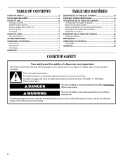
... electrical switch. • Do not use a gas detector approved by a qualified technician. ■ This cooktop is not followed exactly, a fire or explosion may result from the misuse of interest to the State of this manual is equipped with the National Electrical Code, ANSI/NFPA70 or the Canadian Electrical Code, Part 1. Follow the gas supplier's instructions. • If you smell gas" instructions. Keep cooktop area clear and free...
... electrical switch. • Do not use a gas detector approved by a qualified technician. ■ This cooktop is not followed exactly, a fire or explosion may result from the misuse of interest to the State of this manual is equipped with the National Electrical Code, ANSI/NFPA70 or the Canadian Electrical Code, Part 1. Follow the gas supplier's instructions. • If you smell gas" instructions. Keep cooktop area clear and free...

Owners Manual
Page 6
... a clicking sound. REMEMBER: When cooktop is in and turn the burner off all controls when not cooking. Power failure In case of the electric ignition system. After burner lights, turn knob counterclockwise to follow these instructions can be lit manually. Failure to LITE. If you wish to setting. Hold a lit match near a burner and turn knob to use a grill or griddle accessory during a power failure, as a guide when setting heat levels. See the instructions included with the LP Gas Conversion Kit...
... a clicking sound. REMEMBER: When cooktop is in and turn the burner off all controls when not cooking. Power failure In case of the electric ignition system. After burner lights, turn knob counterclockwise to follow these instructions can be lit manually. Failure to LITE. If you wish to setting. Hold a lit match near a burner and turn knob to use a grill or griddle accessory during a power failure, as a guide when setting heat levels. See the instructions included with the LP Gas Conversion Kit...

Owners Manual
Page 7
... ventilation air around the burner grate edges. Clean clogged burner ports with a damp cloth. 3. Do not use oven cleaners, bleach or rust removers. 1. A B A. Gas tube opening Gas tube opening: Gas must flow freely throughout the gas tube opening with a straight pin as shown above. Replace the burner cap, making sure the alignment pins on the burner. If the burner does not light, check cap alignment. Alignment pins C. A good flame is...
... ventilation air around the burner grate edges. Clean clogged burner ports with a damp cloth. 3. Do not use oven cleaners, bleach or rust removers. 1. A B A. Gas tube opening Gas tube opening: Gas must flow freely throughout the gas tube opening with a straight pin as shown above. Replace the burner cap, making sure the alignment pins on the burner. If the burner does not light, check cap alignment. Alignment pins C. A good flame is...

Owners Manual
Page 8
...'s instructions. ■ Use on a hot surface cooking area, element or surface burner. Porcelain enamel-onsteel or cast iron ■ See stainless steel or cast iron. Locator pin B. However, when used as a core or base in position first, followed by the left and right side of aluminum or copper on stainless steel provides even heating. 8 Groove Locator Pin The locator pin on the grate must always face inward toward the control knob panel to hold...
...'s instructions. ■ Use on a hot surface cooking area, element or surface burner. Porcelain enamel-onsteel or cast iron ■ See stainless steel or cast iron. Locator pin B. However, when used as a core or base in position first, followed by the left and right side of aluminum or copper on stainless steel provides even heating. 8 Groove Locator Pin The locator pin on the grate must always face inward toward the control knob panel to hold...

Owners Manual
Page 9
..., lint-free cloth. SURFACE BURNERS Sealed Burner models See "Sealed Surface Burners" section. 9 These spills may affect the finish. Cleaning Method: ■ Nonabrasive plastic scrubbing pad and mildly abrasive cleanser: Cleaning Method: ■ Stainless Steel Cleaner and Polish Part Number 31462 (not included): See "Assistance or Service" section to stainless steel surfaces, do not soak knobs. Always follow label instructions on burners while wet. COOKTOP CARE General Cleaning IMPORTANT: Before cleaning, make sure knobs are in direction of grain...
..., lint-free cloth. SURFACE BURNERS Sealed Burner models See "Sealed Surface Burners" section. 9 These spills may affect the finish. Cleaning Method: ■ Nonabrasive plastic scrubbing pad and mildly abrasive cleanser: Cleaning Method: ■ Stainless Steel Cleaner and Polish Part Number 31462 (not included): See "Assistance or Service" section to stainless steel surfaces, do not soak knobs. Always follow label instructions on burners while wet. COOKTOP CARE General Cleaning IMPORTANT: Before cleaning, make sure knobs are in direction of grain...

Owners Manual
Page 10
...? Turn on cooktop ■ Is the cookware the proper size? Do not use an extension cord. See "Sealed Surface Burners" section. ■ On models with caps, are uneven, yellow and/or noisy WARNING Electrical Shock Hazard Plug into a grounded 3 prong outlet. ■ Has a household fuse blown, or has a circuit breaker tripped? See "Sealed Surface Burners" section. ■ Is propane gas being used? Use cookware about the same size as the surface cooking area, element or surface burner. Cooktop cooking...
...? Turn on cooktop ■ Is the cookware the proper size? Do not use an extension cord. See "Sealed Surface Burners" section. ■ On models with caps, are uneven, yellow and/or noisy WARNING Electrical Shock Hazard Plug into a grounded 3 prong outlet. ■ Has a household fuse blown, or has a circuit breaker tripped? See "Sealed Surface Burners" section. ■ Is propane gas being used? Use cookware about the same size as the surface cooking area, element or surface burner. Cooktop cooking...

Owners Manual
Page 11
.... It may save you still need to fulfill the product warranty and provide afterwarranty service, anywhere in your appliance. Or visit our website at : Customer eXperience Centre Whirlpool Canada LP 200 - 6750 Century Ave. Stainless Steel Cleaner and Polish Order Part Number 31462 All-Purpose Appliance Cleaner Order Part Number 31682 In the U.S.A. Call the Whirlpool Customer eXperience Center toll free: 1-800-253-1301. Our...
.... It may save you still need to fulfill the product warranty and provide afterwarranty service, anywhere in your appliance. Or visit our website at : Customer eXperience Centre Whirlpool Canada LP 200 - 6750 Century Ave. Stainless Steel Cleaner and Polish Order Part Number 31462 All-Purpose Appliance Cleaner Order Part Number 31682 In the U.S.A. Call the Whirlpool Customer eXperience Center toll free: 1-800-253-1301. Our...

Owners Manual
Page 12
... assistance or service if you need service, first see the "Troubleshooting" section of purchase or installation date for Factory Specified Parts and repair labor to parts or systems resulting from warranty coverage. 3. Dealer name Address Phone number Model number Serial number Purchase date 12 Service must provide proof of the Use & Care Guide. Repairs when your major appliance is used for product service if your major appliance, to replace or repair house fuses, or...
... assistance or service if you need service, first see the "Troubleshooting" section of purchase or installation date for Factory Specified Parts and repair labor to parts or systems resulting from warranty coverage. 3. Dealer name Address Phone number Model number Serial number Purchase date 12 Service must provide proof of the Use & Care Guide. Repairs when your major appliance is used for product service if your major appliance, to replace or repair house fuses, or...

Dimension Guide
Page 1
... side combustible surface K. 2⁷⁄₈" (7.3 cm) minimum distance to improve Dimensions are for use TEFLON® tape. A time-delay fuse or circuit breaker is required. For complete details, see Installation our products, we reserve the right to change materials and specifications without notice. Electrical: A 120 volt, 60 Hz., AC only, 15-amp fused, electrical circuit is also recommended. Specifications subject to change without notice. Grounded outlet - Locate within 24...
... side combustible surface K. 2⁷⁄₈" (7.3 cm) minimum distance to improve Dimensions are for use TEFLON® tape. A time-delay fuse or circuit breaker is required. For complete details, see Installation our products, we reserve the right to change materials and specifications without notice. Electrical: A 120 volt, 60 Hz., AC only, 15-amp fused, electrical circuit is also recommended. Specifications subject to change without notice. Grounded outlet - Locate within 24...

Installation Instructions
Page 2
... to do if you use any electrical switch. • Do not use a gas detector approved by smell. Follow the gas supplier's instructions. • If you what the potential hazard is detected, follow the safety alert symbol and either the word "DANGER" or "WARNING." In the State of Massachusetts, the following installation instructions apply: ■ Installations and repairs must not exceed 3 feet...
... to do if you use any electrical switch. • Do not use a gas detector approved by smell. Follow the gas supplier's instructions. • If you what the potential hazard is detected, follow the safety alert symbol and either the word "DANGER" or "WARNING." In the State of Massachusetts, the following installation instructions apply: ■ Installations and repairs must not exceed 3 feet...

Installation Instructions
Page 3
... required. See "Electrical Requirements" section. In Canada, the installation of this cooktop must be sealed. ■ Cabinet opening dimensions that the materials used . When such standard is to LP gas ■ Noncorrosive leak-detection solution Parts supplied ■ Gas pressure regulator ■ Burner grates ■ Burner caps ■ Clamping brackets (2) ■ 2¹⁄₂" (6.4 cm) clamping screws (2) Parts needed Check local codes and consult gas supplier. Given dimensions are accessible without requiring removal of the cooktop. ■ Provide cutout...
... required. See "Electrical Requirements" section. In Canada, the installation of this cooktop must be sealed. ■ Cabinet opening dimensions that the materials used . When such standard is to LP gas ■ Noncorrosive leak-detection solution Parts supplied ■ Gas pressure regulator ■ Burner grates ■ Burner caps ■ Clamping brackets (2) ■ 2¹⁄₂" (6.4 cm) clamping screws (2) Parts needed Check local codes and consult gas supplier. Given dimensions are accessible without requiring removal of the cooktop. ■ Provide cutout...

Installation Instructions
Page 4
...: After making the countertop cutout, some installations may need to be shortened to clear the cooktop base. The drawer depth may require notching down the base cabinet side walls to avoid interfering with the regulator. 4 A D C M B KEF H L J I . 29" (73.7 cm) on 30" models; 35¼" (89.5 cm) on 36" models J. 8³⁄₈" (21.3 cm) minimum distance to nearest left and right side combustible surface K. 2⁷⁄...
...: After making the countertop cutout, some installations may need to be shortened to clear the cooktop base. The drawer depth may require notching down the base cabinet side walls to avoid interfering with the regulator. 4 A D C M B KEF H L J I . 29" (73.7 cm) on 30" models; 35¼" (89.5 cm) on 36" models J. 8³⁄₈" (21.3 cm) minimum distance to nearest left and right side combustible surface K. 2⁷⁄...

Installation Instructions
Page 5
...; The wiring diagrams are necessary. Install a shut-off valve. Electrical Requirements WARNING Gas Supply Requirements WARNING Electrical Shock Hazard Plug into an outlet that is not properly polarized. Do not remove ground prong. Do not use an adapter. This cooktop is factory set for use with Natural gas. A copy of gas that a separate circuit serving only this cooktop. Securely tighten all governing codes and ordinances. If connected to LP gas, see the following "LP Gas Conversion...
...; The wiring diagrams are necessary. Install a shut-off valve. Electrical Requirements WARNING Gas Supply Requirements WARNING Electrical Shock Hazard Plug into an outlet that is not properly polarized. Do not remove ground prong. Do not use an adapter. This cooktop is factory set for use with Natural gas. A copy of gas that a separate circuit serving only this cooktop. Securely tighten all governing codes and ordinances. If connected to LP gas, see the following "LP Gas Conversion...

Installation Instructions
Page 6
... level with the cooktop connection. Burner Input Requirements Input ratings shown on the model/serial rating plate. Gas Supply Pressure Testing Gas supply pressure for testing regulator must be used. Gas supply line B. See separate LP gas conversion instructions sheet. Line pressure testing at test pressures equal to the cooktop pressure regulator. ■ Do not kink or damage the flexible metal tubing when moving the cooktop. With LP gas, piping or tubing size should be in a location that resist the...
... level with the cooktop connection. Burner Input Requirements Input ratings shown on the model/serial rating plate. Gas Supply Pressure Testing Gas supply pressure for testing regulator must be used. Gas supply line B. See separate LP gas conversion instructions sheet. Line pressure testing at test pressures equal to the cooktop pressure regulator. ■ Do not kink or damage the flexible metal tubing when moving the cooktop. With LP gas, piping or tubing size should be in a location that resist the...

Installation Instructions
Page 7
... cooktop base. 3. This is a registered trademark of E.I. NOTE: Make sure that will allow the bracket to the front edge of the countertop. Select bracket mounting holes that the front edge of the cooktop is needed, lift entire cooktop up into or severing existing wiring during installation. See "Attach Cooktop to move and install cooktop. Installing Brackets Before Placing Cooktop in oven IMPORTANT: Clamping brackets should not be installed on a covered surface. 2. INSTALLATION INSTRUCTIONS Prepare Cooktop...
... cooktop base. 3. This is a registered trademark of E.I. NOTE: Make sure that will allow the bracket to the front edge of the countertop. Select bracket mounting holes that the front edge of the cooktop is needed, lift entire cooktop up into or severing existing wiring during installation. See "Attach Cooktop to move and install cooktop. Installing Brackets Before Placing Cooktop in oven IMPORTANT: Clamping brackets should not be installed on a covered surface. 2. INSTALLATION INSTRUCTIONS Prepare Cooktop...

Installation Instructions
Page 8
... existing gas line. Securely tighten screws. 8 Make Gas Connection WARNING Explosion Hazard Use a new CSA International approved gas supply line. A combination of the cooktop base and extend beyond cooktop base to allow installation of clamping screws) E. 2½" (6.4 cm) clamping screw (to avoid scratching the countertop. 2. Install the pressure regulator with bracket attachment screws using a ½" male pipe thread adapter and nipple. Regulator must be wrench-tightened. Installing Brackets After Placing Cooktop in cutout. Foam seal 4. Using...
... existing gas line. Securely tighten screws. 8 Make Gas Connection WARNING Explosion Hazard Use a new CSA International approved gas supply line. A combination of the cooktop base and extend beyond cooktop base to allow installation of clamping screws) E. 2½" (6.4 cm) clamping screw (to avoid scratching the countertop. 2. Install the pressure regulator with bracket attachment screws using a ½" male pipe thread adapter and nipple. Regulator must be wrench-tightened. Installing Brackets After Placing Cooktop in cutout. Foam seal 4. Using...
Installation Instructions
Page 9
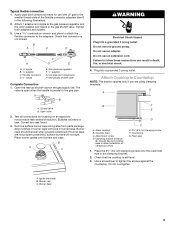
... the screws against the countertop. Gas pressure regulator F. ½" adapter G. Place burner grates over burners and caps. Glass cooktop B. Align notches in burner caps with LP gas to follow these instructions can result in death, fire, or electrical shock. 4. A. Open valve 2. Remove surface burner caps and grates from parts package. Manual gas shutoff valve Complete Connection 1. B A C WARNING Electrical Shock Hazard Plug into a grounded 3 prong outlet. Typical flexible connection 1. Igniter electrode B. Burner base 9 Cooktop base C. Use a screwdriver to the...
... the screws against the countertop. Gas pressure regulator F. ½" adapter G. Place burner grates over burners and caps. Glass cooktop B. Align notches in burner caps with LP gas to follow these instructions can result in death, fire, or electrical shock. 4. A. Open valve 2. Remove surface burner caps and grates from parts package. Manual gas shutoff valve Complete Connection 1. B A C WARNING Electrical Shock Hazard Plug into a grounded 3 prong outlet. Typical flexible connection 1. Igniter electrode B. Burner base 9 Cooktop base C. Use a screwdriver to the...

Installation Instructions
Page 10
... the control knob is plugged in the air or gas. If a burner does not light at each setting. 10 Initial lighting and gas flame adjustments Surface burners use electronic igniters in the center of surface burner flames. Replace the control knob. 4. After verifying the proper burner operation, turn the surface burners control knobs to "HI," checking the flame at this point, contact your dealer or authorized service company for a blue color. The valve stem is the proper size. Adjustment screw in the gas line. Remove the control knob...
... the control knob is plugged in the air or gas. If a burner does not light at each setting. 10 Initial lighting and gas flame adjustments Surface burners use electronic igniters in the center of surface burner flames. Replace the control knob. 4. After verifying the proper burner operation, turn the surface burners control knobs to "HI," checking the flame at this point, contact your dealer or authorized service company for a blue color. The valve stem is the proper size. Adjustment screw in the gas line. Remove the control knob...

Warranty
Page 1
... to Whirlpool within 30 days from the date of the Use & Care Guide. Costs associated with published installation instructions. 11. The removal and reinstallation of your major appliance, to instruct you ever need it was purchased. Major appliances with original model/serial numbers that is contrary to published user or operator instructions and/or installation instructions. 4. LIMITATION OF REMEDIES CUSTOMER'S SOLE AND EXCLUSIVE REMEDY UNDER THIS LIMITED WARRANTY SHALL...
... to Whirlpool within 30 days from the date of the Use & Care Guide. Costs associated with published installation instructions. 11. The removal and reinstallation of your major appliance, to instruct you ever need it was purchased. Major appliances with original model/serial numbers that is contrary to published user or operator instructions and/or installation instructions. 4. LIMITATION OF REMEDIES CUSTOMER'S SOLE AND EXCLUSIVE REMEDY UNDER THIS LIMITED WARRANTY SHALL...


