
English Manual
Page 2
... state to defect in material or workmanship in this manual. Remove the PART IDENTIFICATION CHART and the PART LIST/EXPLODED DRAWING before beginning assembly. SEARS, ROEBUCK AND CO., DEPT. 817WA, HOFFMAN ESTATES, IL 60179 2 This warranty gives you specific legal rights, and you ...charge. TABLE OF CONTENTS FULL 90 DAY WARRANTY 2 IMPORTANT PRECAUTIONS 3 BEFORE YOU BEGIN 4 ASSEMBLY 5 HOW TO USE THE HOME GYM SYSTEM 26 WEIGHT RESISTANCE CHART 28 TROUBLE-SHOOTING AND MAINTENANCE 29 CABLE DIAGRAMS 30 ORDERING REPLACEMENT PARTS Back Cover Note: A PART IDENTIFICATION CHART and a PART ...
... state to defect in material or workmanship in this manual. Remove the PART IDENTIFICATION CHART and the PART LIST/EXPLODED DRAWING before beginning assembly. SEARS, ROEBUCK AND CO., DEPT. 817WA, HOFFMAN ESTATES, IL 60179 2 This warranty gives you specific legal rights, and you ...charge. TABLE OF CONTENTS FULL 90 DAY WARRANTY 2 IMPORTANT PRECAUTIONS 3 BEFORE YOU BEGIN 4 ASSEMBLY 5 HOW TO USE THE HOME GYM SYSTEM 26 WEIGHT RESISTANCE CHART 28 TROUBLE-SHOOTING AND MAINTENANCE 29 CABLE DIAGRAMS 30 ORDERING REPLACEMENT PARTS Back Cover Note: A PART IDENTIFICATION CHART and a PART ...

English Manual
Page 5
... part is divided into four stages: 1) frame assembly, 2) press and butterfly arm assembly, 3) cable and pulley assembly and 4) seat and backrest assembly. Assembly will also be sure that assembly stage. • For help identifying the small parts used in assembly, use the PART IDENTIFICATION CHART located in the drawings.... • Tighten all parts in a cleared area and remove the packing materials; do not dispose of the packing materials until you assemble them, unless instructed to the Weight Base (14) with two 5/16" x 2 3/4" Bolts (55), two 5/16" Washers (20) ...
... part is divided into four stages: 1) frame assembly, 2) press and butterfly arm assembly, 3) cable and pulley assembly and 4) seat and backrest assembly. Assembly will also be sure that assembly stage. • For help identifying the small parts used in assembly, use the PART IDENTIFICATION CHART located in the drawings.... • Tighten all parts in a cleared area and remove the packing materials; do not dispose of the packing materials until you assemble them, unless instructed to the Weight Base (14) with two 5/16" x 2 3/4" Bolts (55), two 5/16" Washers (20) ...

English Manual
Page 13
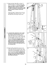
... the Right Arm (5).Thread a 3/8" Nylon Locknut (42) onto the Bolt, but do not overtighten the bolts and nuts attaching the pulleys. CABLE ASSEMBLY 23. Locate and open the parts bags labeled 23 "CABLE ASSEMBLY" and "PULLEYS." During steps 23 through the bracket on the Leg Press Upright (4) with a 3/8" x 2" Bolt (50) and a 3/8" Nylon Locknut (42...
... the Right Arm (5).Thread a 3/8" Nylon Locknut (42) onto the Bolt, but do not overtighten the bolts and nuts attaching the pulleys. CABLE ASSEMBLY 23. Locate and open the parts bags labeled 23 "CABLE ASSEMBLY" and "PULLEYS." During steps 23 through the bracket on the Leg Press Upright (4) with a 3/8" x 2" Bolt (50) and a 3/8" Nylon Locknut (42...

English Manual
Page 14
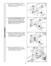
...Bolt, but do not fully tighten it. Refer to hold the Cable in place. Leave just enough room for easier part identification. Locate one of the pre-assembled pairs of the Pulley. 80 50 42 82 85 4 CABLE ASSEMBLY 28. Wrap the Butterfly Cable (85) around a 3 1/2" Pulley (82) as shown and... be down 89 80 27. Be sure that the Cable is between the Cable Trap (80) and the Pulley, and that the Cable Trap is shown removed 28 for the Cable to hold the Cable in the groove...
...Bolt, but do not fully tighten it. Refer to hold the Cable in place. Leave just enough room for easier part identification. Locate one of the pre-assembled pairs of the Pulley. 80 50 42 82 85 4 CABLE ASSEMBLY 28. Wrap the Butterfly Cable (85) around a 3 1/2" Pulley (82) as shown and... be down 89 80 27. Be sure that the Cable is between the Cable Trap (80) and the Pulley, and that the Cable Trap is shown removed 28 for the Cable to hold the Cable in the groove...

English Manual
Page 15
... Pulley (82). Attach the Pulley to the Top Frame (2) with two holes should be routed from the direction shown. 42 2 50 82 86 15 CABLE ASSEMBLY 29. It is on the indicated side of Pulley Plates (31) and 3 1/2" Pulleys 31 (82). The end of the Pulley Plates (31) with...66), a 3/8" Washer (38) and a 3/8" Nylon Jam Nut (43). Note: The 3 1/2" Pulley (82) in this is 29 pre-assembled. Locate the High Cable (86)-this step is the shortest remaining Cable. Refer to the Top Frame (2). Tighten the 3/8" x 3 1/2" Bolt (66) and the 3/8" Nylon Locknut (42), with the ball is ...
... Pulley (82). Attach the Pulley to the Top Frame (2) with two holes should be routed from the direction shown. 42 2 50 82 86 15 CABLE ASSEMBLY 29. It is on the indicated side of Pulley Plates (31) and 3 1/2" Pulleys 31 (82). The end of the Pulley Plates (31) with...66), a 3/8" Washer (38) and a 3/8" Nylon Jam Nut (43). Note: The 3 1/2" Pulley (82) in this is 29 pre-assembled. Locate the High Cable (86)-this step is the shortest remaining Cable. Refer to the Top Frame (2). Tighten the 3/8" x 3 1/2" Bolt (66) and the 3/8" Nylon Locknut (42), with the ball is ...
English Manual
Page 16
... (40). 34. Attach the Pulley and two Pulley Covers (62) to a Small "U" 33 Bracket (32) with a 3/8" x 4" Bolt (76), two 3/8" Washers (38) and a 3/8" Nylon Locknut (42). CABLE ASSEMBLY 33. Make sure that the Pulley Covers are turned so the wide tabs are showing above the Nylon Locknut, as shown in the inset drawing.... the Pulley should turn easily. Locate the Rear Cable (87)-this side 1 35 87 38 42 1 86 37 44 76 38 87 82 38 42 62 16 Do not overtighten the Nylon Locknut; ...
... (40). 34. Attach the Pulley and two Pulley Covers (62) to a Small "U" 33 Bracket (32) with a 3/8" x 4" Bolt (76), two 3/8" Washers (38) and a 3/8" Nylon Locknut (42). CABLE ASSEMBLY 33. Make sure that the Pulley Covers are turned so the wide tabs are showing above the Nylon Locknut, as shown in the inset drawing.... the Pulley should turn easily. Locate the Rear Cable (87)-this side 1 35 87 38 42 1 86 37 44 76 38 87 82 38 42 62 16 Do not overtighten the Nylon Locknut; ...

English Manual
Page 17
...) around a 3 1/2" Pulley (82). Refer to the Ab Upright (1) with a 3/8" x 3 1/2" Bolt (66), a 3/8" Washer (38) and a 3/8" Jam Nut (43). ing. Route the Press Cable (88) over the indicated 36 3 1/2" Pulley (82) attached to hold the Cable in place. 31 50 82 87 CABLE ASSEMBLY 80 87 37. 36. The Cable must be routed from the direction shown.
...) around a 3 1/2" Pulley (82). Refer to the Ab Upright (1) with a 3/8" x 3 1/2" Bolt (66), a 3/8" Washer (38) and a 3/8" Jam Nut (43). ing. Route the Press Cable (88) over the indicated 36 3 1/2" Pulley (82) attached to hold the Cable in place. 31 50 82 87 CABLE ASSEMBLY 80 87 37. 36. The Cable must be routed from the direction shown.
English Manual
Page 18
... Pulley to the Leg Lever 38 (15) with a 3/8" x 2" Bolt (50) and a 3/8" Nylon Locknut (42). 89 50 82 42 14 18 CABLE ASSEMBLY 38. Wrap the Low Cable (89) around a "V" Pulley (81). Feed the Low Cable under the 3 1/2" Pro Pulley (97) and the row tube on the side shown. The ball on the... Cable must be on the Pulley Base (79). Find the Low Cable (89)-this is the shortest of the two remaining Cables. Slide the "V" Pulley and a Large Cable Trap (83) onto the 3/8" x...
... Pulley to the Leg Lever 38 (15) with a 3/8" x 2" Bolt (50) and a 3/8" Nylon Locknut (42). 89 50 82 42 14 18 CABLE ASSEMBLY 38. Wrap the Low Cable (89) around a "V" Pulley (81). Feed the Low Cable under the 3 1/2" Pro Pulley (97) and the row tube on the side shown. The ball on the... Cable must be on the Pulley Base (79). Find the Low Cable (89)-this is the shortest of the two remaining Cables. Slide the "V" Pulley and a Large Cable Trap (83) onto the 3/8" x...

English Manual
Page 19
... Top 44 Frame (2) with a 3/8" x 2" Bolt (50) and a 3/8" Nylon Locknut (42). The Cable must be routed from the direction shown. 2 42 50 82 89 CABLE ASSEMBLY 43. See the inset drawing. Be sure that the Cable and Pulley move smoothly. 84 89 82 84 44. Note: This may come pre...-assembled. 80 82 Route the Low Cable (89) through the Large "U" Bracket (84) and the 3 ...
... Top 44 Frame (2) with a 3/8" x 2" Bolt (50) and a 3/8" Nylon Locknut (42). The Cable must be routed from the direction shown. 2 42 50 82 89 CABLE ASSEMBLY 43. See the inset drawing. Be sure that the Cable and Pulley move smoothly. 84 89 82 84 44. Note: This may come pre...-assembled. 80 82 Route the Low Cable (89) through the Large "U" Bracket (84) and the 3 ...

English Manual
Page 20
...) to the Large "U" Bracket (84) with a 1/4" Nylon Locknut (44) and a 1/4" Washer (37). Be sure that the Cable Trap (80) is turned as shown to hold the Cable in this step is shown dis-assembled for easier part identification. Do not completely tighten the Nylon Locknut. Attach the Small "U" Bracket (32) to the indicated...). 89 37 44 44 37 84 89 32 40 68 37 44 25 44 37 84 88 CABLE ASSEMBLY 88 80 42 82 50 13 20 It should be threaded onto the end of the Cable so only a couple of threads are showing above the Nylon Locknut, as shown in the inset drawing...
...) to the Large "U" Bracket (84) with a 1/4" Nylon Locknut (44) and a 1/4" Washer (37). Be sure that the Cable Trap (80) is turned as shown to hold the Cable in this step is shown dis-assembled for easier part identification. Do not completely tighten the Nylon Locknut. Attach the Small "U" Bracket (32) to the indicated...). 89 37 44 44 37 84 89 32 40 68 37 44 25 44 37 84 88 CABLE ASSEMBLY 88 80 42 82 50 13 20 It should be threaded onto the end of the Cable so only a couple of threads are showing above the Nylon Locknut, as shown in the inset drawing...

English Manual
Page 21
... shown). 31 50 82 80 88 CABLE ASSEMBLY 50. Route the Press Cable (88) over the indicated 3 1/2" Pulley (82) attached to the inset draw- The Cable must be routed from the direction shown. Wrap the Press Cable (88) around the 3 1/2" Pulley (82) attached to hold the Cable in place. 88 82 66 80 ... 12 4 38 43 42 80 82 21 Wrap the Press Cable (88) around a 3 1/2" Pulley (82). Refer to the Pulley 49 Plates (31). Be sure that the Cable Trap is pre-assembled. Be sure that the Cable Trap is shown dis-assembled for easier part identification. It is turned to the Leg Press...
... shown). 31 50 82 80 88 CABLE ASSEMBLY 50. Route the Press Cable (88) over the indicated 3 1/2" Pulley (82) attached to the inset draw- The Cable must be routed from the direction shown. Wrap the Press Cable (88) around the 3 1/2" Pulley (82) attached to hold the Cable in place. 88 82 66 80 ... 12 4 38 43 42 80 82 21 Wrap the Press Cable (88) around a 3 1/2" Pulley (82). Refer to the Pulley 49 Plates (31). Be sure that the Cable Trap is pre-assembled. Be sure that the Cable Trap is shown dis-assembled for easier part identification. It is turned to the Leg Press...

English Manual
Page 22
...74). Wrap the Press Cable (88) around a 3 1/2" 53 Pulley (82). Do not fully tighten the Nylon Locknut until step 57. 55 88 74 82 80 82 43 80 9 22 Slide another 3 1/2" Pulley (82) with a 3/8" x 2" Bolt (50) and a 3/8" Nylon Jam Nut (43). 50 81 4 CABLE ASSEMBLY 88 43 53. Attach... the Pulley and a Cable Trap (80) to the lower 54 bracket on the Leg Press Upright (4) with a 3/8" x 3 1/2" Bolt (66), a 3/8" Washer (38) and a...
...74). Wrap the Press Cable (88) around a 3 1/2" 53 Pulley (82). Do not fully tighten the Nylon Locknut until step 57. 55 88 74 82 80 82 43 80 9 22 Slide another 3 1/2" Pulley (82) with a 3/8" x 2" Bolt (50) and a 3/8" Nylon Jam Nut (43). 50 81 4 CABLE ASSEMBLY 88 43 53. Attach... the Pulley and a Cable Trap (80) to the lower 54 bracket on the Leg Press Upright (4) with a 3/8" x 3 1/2" Bolt (66), a 3/8" Washer (38) and a...

English Manual
Page 23
...91) onto the Bolt, but do not fully tighten it. Route the Press Cable (88) around a "V" 56 Pulley (81). Tighten the 3/8" x 4 1/2" Bolt (74) and the 3/8" Nylon Jam Nut (43). 88 42 74 8 9 43 82 80 88 58. CABLE ASSEMBLY 56. Note: The 3 1/2" Pulley (82) used in this step was... attached in place and that the Large Cable Trap is routed as shown. Leave enough room between the two Jam Nuts for easier part identification...
...91) onto the Bolt, but do not fully tighten it. Route the Press Cable (88) around a "V" 56 Pulley (81). Tighten the 3/8" x 4 1/2" Bolt (74) and the 3/8" Nylon Jam Nut (43). 88 42 74 8 9 43 82 80 88 58. CABLE ASSEMBLY 56. Note: The 3 1/2" Pulley (82) used in this step was... attached in place and that the Large Cable Trap is routed as shown. Leave enough room between the two Jam Nuts for easier part identification...
English Manual
Page 30
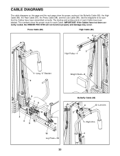
... 10 Leg Press-13 30 Butterfly Cable (85) 4 5-Left Arm 2 1-Right Arm 3 Use the diagrams to be sure that the Cables have been assembled correctly. CABLE DIAGRAMS The cable diagrams on this page and the next page show the proper route for each Cable have not been correctly routed, the WEIDER PRO 9735 will not function properly and damage...
... 10 Leg Press-13 30 Butterfly Cable (85) 4 5-Left Arm 2 1-Right Arm 3 Use the diagrams to be sure that the Cables have been assembled correctly. CABLE DIAGRAMS The cable diagrams on this page and the next page show the proper route for each Cable have not been correctly routed, the WEIDER PRO 9735 will not function properly and damage...


