
English Manual
Page 1
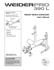
Save this equipment. Model No. 831.15928.0 Serial No. Write the serial number in this manual before using this manual for future reference. Hoffman Estates, IL 60179 CAUTION Read all precautions and instructions in the space above for future reference. WEIGHT BENCH EXERCISER Userʼs Manual Serial Number Decal (under the seat) • Assembly • Operation • Maintenance • Part List and Drawing Sears, Roebuck and Co.
Save this equipment. Model No. 831.15928.0 Serial No. Write the serial number in this manual before using this manual for future reference. Hoffman Estates, IL 60179 CAUTION Read all precautions and instructions in the space above for future reference. WEIGHT BENCH EXERCISER Userʼs Manual Serial Number Decal (under the seat) • Assembly • Operation • Maintenance • Part List and Drawing Sears, Roebuck and Co.
English Manual
Page 2
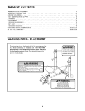
Note: The decal(s) may not be shown at actual size. 2 Apply the decal in the location shown. TABLE OF CONTENTS WARNING DECAL PLACEMENT 2 IMPORTANT PRECAUTIONS 3 BEFORE YOU BEGIN 4 PART IDENTIFICATION CHART 5 ASSEMBLY 6 ADJUSTMENT 13 EXERCISE GUIDELINES 15 PART LIST 17 EXPLODED DRAWING 18 ORDERING REPLACEMENT PARTS Back Cover 90 DAY FULL WARRANTY Back Cover WARNING DECAL PLACEMENT This drawing shows the location(s) of the warning decal(s). If a decal is missing or illegible, call 1-877-992-5999 and request a free replacement decal.
Note: The decal(s) may not be shown at actual size. 2 Apply the decal in the location shown. TABLE OF CONTENTS WARNING DECAL PLACEMENT 2 IMPORTANT PRECAUTIONS 3 BEFORE YOU BEGIN 4 PART IDENTIFICATION CHART 5 ASSEMBLY 6 ADJUSTMENT 13 EXERCISE GUIDELINES 15 PART LIST 17 EXPLODED DRAWING 18 ORDERING REPLACEMENT PARTS Back Cover 90 DAY FULL WARRANTY Back Cover WARNING DECAL PLACEMENT This drawing shows the location(s) of the warning decal(s). If a decal is missing or illegible, call 1-877-992-5999 and request a free replacement decal.
English Manual
Page 3
IMPORTANT PRECAUTIONS WARNING: To reduce the risk of all precautions. 4. Make sure that there is longer than 6 ft. (1.8 m) with pre-existing health problems. 2. Inspect and properly tighten all warnings on the leg lever. Replace any exercise program, consult your partner should stand behind you to catch the barbell if you cannot complete a repetition. 15. Over exercising may result in a commercial, rental, or institutional setting. 5. Always keep hands and feet away from the weight bench. 9. Wear appropriate clothes while exercising; Do not use a barbell that the ...
IMPORTANT PRECAUTIONS WARNING: To reduce the risk of all precautions. 4. Make sure that there is longer than 6 ft. (1.8 m) with pre-existing health problems. 2. Inspect and properly tighten all warnings on the leg lever. Replace any exercise program, consult your partner should stand behind you to catch the barbell if you cannot complete a repetition. 15. Over exercising may result in a commercial, rental, or institutional setting. 5. Always keep hands and feet away from the weight bench. 9. Wear appropriate clothes while exercising; Do not use a barbell that the ...
English Manual
Page 4
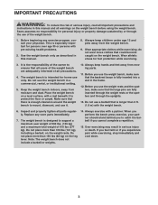
... tone your body, build dramatic muscle size and strength, or improve your benefit, read this manual. reading this manual. If you for selecting the versatile WEIDER PRO™ 390 L Olympic weight bench. The model number and the location of the serial number decal are labeled. BEFORE YOU BEGIN Thank you have questions...
... tone your body, build dramatic muscle size and strength, or improve your benefit, read this manual. reading this manual. If you for selecting the versatile WEIDER PRO™ 390 L Olympic weight bench. The model number and the location of the serial number decal are labeled. BEFORE YOU BEGIN Thank you have questions...
English Manual
Page 5
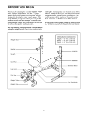
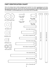
IMPORTANT: If you cannot find a part in the hardware kit, check to identify small parts used in parentheses by each drawing is missing, please call 1-877-992-5999. M10 Curved Washer (58) M10 Washer (35) ST4.2 x 20mm Screw (53) ST4.2 x 10mm Screw (17) M10 x 18mm Screw (34) M6 x 25mm Screw (39) M6 x 48mm Screw (41) M10 x 180mm Bolt (54) M10 x 192mm Bolt (43) M8 Washer (36) M6 Washer (42) M10 Locknut (37) M10 x 58mm Carriage Bolt (40) M8 x 65mm Screw (56) M10 x 82mm Carriage Bolt (55) M10 x 85mm Bolt (45) M10 x 101mm Bolt (38) M10 x 110mm Bolt (44) 5 To avoid damaging parts, do not ...
IMPORTANT: If you cannot find a part in the hardware kit, check to identify small parts used in parentheses by each drawing is missing, please call 1-877-992-5999. M10 Curved Washer (58) M10 Washer (35) ST4.2 x 20mm Screw (53) ST4.2 x 10mm Screw (17) M10 x 18mm Screw (34) M6 x 25mm Screw (39) M6 x 48mm Screw (41) M10 x 180mm Bolt (54) M10 x 192mm Bolt (43) M8 Washer (36) M6 Washer (42) M10 Locknut (37) M10 x 58mm Carriage Bolt (40) M8 x 65mm Screw (56) M10 x 82mm Carriage Bolt (55) M10 x 85mm Bolt (45) M10 x 101mm Bolt (38) M10 x 110mm Bolt (44) 5 To avoid damaging parts, do not ...

English Manual
Page 6
ASSEMBLY • Assembly requires two persons. • Because of this page before your begin. Attach the Front Leg (4) to walk around the weight bench as you assemble it will be more convenient if you complete all parts in the location where it . • Place all assembly steps. • To identify small parts, see page 5. • The following tools (not included) may be required for assembly: two adjustable wrenches one rubber mallet one standard screwdriver one Phillips screwdriver Assembly will be used. Orient the Front Stabilizer (2) so that there is enough clearance to ...
ASSEMBLY • Assembly requires two persons. • Because of this page before your begin. Attach the Front Leg (4) to walk around the weight bench as you assemble it will be more convenient if you complete all parts in the location where it . • Place all assembly steps. • To identify small parts, see page 5. • The following tools (not included) may be required for assembly: two adjustable wrenches one rubber mallet one standard screwdriver one Phillips screwdriver Assembly will be used. Orient the Front Stabilizer (2) so that there is enough clearance to ...
English Manual
Page 7
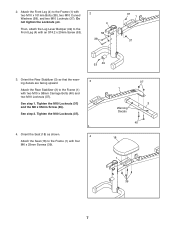
Do not tighten the Locknuts yet. See step 2. Orient the Seat (18) as shown. 4 Attach the Seat (18) to the Frame (1) with four M6 x 25mm Screws (39). 37 1 3 Warning Decals 40 18 1 39 7 Tighten the M10 Locknuts (37) and the M8 x 65mm Screw (56). Tighten the M10 Locknuts (37). 4. Orient the Rear Stabilizer (3) so that the warning decals are facing upward. 3 Attach the Rear Stabilizer (3) to the Frame (1) with two M10 x 58mm Carriage Bolts (40) and two M10 Locknuts (37). Then, attach the Leg Lever Bumper (49) to the Frame (1) with an ST4.2 x 20mm Screw (53). 2 4 58...
Do not tighten the Locknuts yet. See step 2. Orient the Seat (18) as shown. 4 Attach the Seat (18) to the Frame (1) with four M6 x 25mm Screws (39). 37 1 3 Warning Decals 40 18 1 39 7 Tighten the M10 Locknuts (37) and the M8 x 65mm Screw (56). Tighten the M10 Locknuts (37). 4. Orient the Rear Stabilizer (3) so that the warning decals are facing upward. 3 Attach the Rear Stabilizer (3) to the Frame (1) with two M10 x 58mm Carriage Bolts (40) and two M10 Locknuts (37). Then, attach the Leg Lever Bumper (49) to the Frame (1) with an ST4.2 x 20mm Screw (53). 2 4 58...
English Manual
Page 8
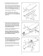
Orient the Backrest Frames (16) so that the welded tubes are in the Frame (1). Orient the Backrest (19) as shown. Insert the end of the Backrest Brace (15) into one of the included grease to an M10 x 85mm Bolt (45). Do not overtighten the Locknut; Attach the Leg Lever (5) to the Front Leg (4) with the Bolt, two M10 Washers (35), and an M10 Locknut (37). 5. Do not tighten the Screws yet. 5 54 35 Grease Welded Tubes 42 41 19 16 42 35 37 41 15 6. Attach the Backrest Frames (16) to the Backrest Frames (16) with the Bolt, two M10 Washers (35), and an M10 Locknut (37). Do not ...
Orient the Backrest Frames (16) so that the welded tubes are in the Frame (1). Orient the Backrest (19) as shown. Insert the end of the Backrest Brace (15) into one of the included grease to an M10 x 85mm Bolt (45). Do not overtighten the Locknut; Attach the Leg Lever (5) to the Front Leg (4) with the Bolt, two M10 Washers (35), and an M10 Locknut (37). 5. Do not tighten the Screws yet. 5 54 35 Grease Welded Tubes 42 41 19 16 42 35 37 41 15 6. Attach the Backrest Frames (16) to the Backrest Frames (16) with the Bolt, two M10 Washers (35), and an M10 Locknut (37). Do not ...
English Manual
Page 9
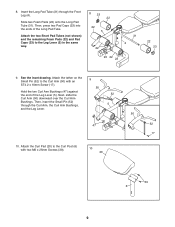
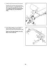
Then, press two Pad Caps (23) into the ends of the Leg Lever (5). Attach the tether on the Small Pin (52) to the Leg Lever (5) in the same way. 8 23 22 22 5 22 31 4 23 22 23 22 23 9. Then, insert the Small Pin (52) through the Front Leg (4). Slide two Foam Pads (22) onto the Long Pad Tube (31). Attach the two Short Pad Tubes (not shown) and the remaining Foam Pads (22) and Pad Caps (23) to the Curl Arm (50) with two M6 x 25mm Screws (39). 10 20 50 52 17 39 6 9 Insert the Long Pad Tube (31) through the Curl Arm, the Curl Arm Bushings, and the Leg Lever. 9 50 52 5 47 10...
Then, press two Pad Caps (23) into the ends of the Leg Lever (5). Attach the tether on the Small Pin (52) to the Leg Lever (5) in the same way. 8 23 22 22 5 22 31 4 23 22 23 22 23 9. Then, insert the Small Pin (52) through the Front Leg (4). Slide two Foam Pads (22) onto the Long Pad Tube (31). Attach the two Short Pad Tubes (not shown) and the remaining Foam Pads (22) and Pad Caps (23) to the Curl Arm (50) with two M6 x 25mm Screws (39). 10 20 50 52 17 39 6 9 Insert the Long Pad Tube (31) through the Curl Arm, the Curl Arm Bushings, and the Leg Lever. 9 50 52 5 47 10...
English Manual
Page 10
Insert a Base Stabilizer (9) into one of the adjustment holes in the same way. 12 9 7 34 34 35 9 35 34 10 Insert the Curl Post (6) into the Front Leg (4). 11 Insert the Curl Post Knob (24) into the Front Leg (4) and into the Base (7). Attach the other Base Stabilizer (9) to the Base (7) in the Curl Post (6), and tighten the Curl Post Knob. Make sure that the Curl Post Knob is inserted through one of the adjustment holes. 24 6 4 12. Attach the Base Stabilizer with five M10 x 18mm Screws (34) and five M10 Washers (35). 11.
Insert a Base Stabilizer (9) into one of the adjustment holes in the same way. 12 9 7 34 34 35 9 35 34 10 Insert the Curl Post (6) into the Front Leg (4). 11 Insert the Curl Post Knob (24) into the Front Leg (4) and into the Base (7). Attach the other Base Stabilizer (9) to the Base (7) in the Curl Post (6), and tighten the Curl Post Knob. Make sure that the Curl Post Knob is inserted through one of the adjustment holes. 24 6 4 12. Attach the Base Stabilizer with five M10 x 18mm Screws (34) and five M10 Washers (35). 11.
English Manual
Page 11
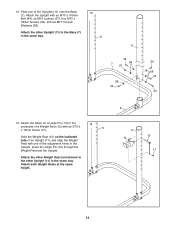
Attach the other Upright (11) in the same way. Attach the Upright with an ST4.2 x 10mm Screw (17). 11 Hold the Weight Rest (12) on a Large Pin (13) to the Base (7) in the Upright. Attach both Weight Rests at the same height. 9 11 12 13 17 11 13. Attach the tether on the indicated side of an Upright (11), and align the Weight Rest with one of the adjustment holes in the same way. 13 11 11 34 7 37 58 58 34 34 58 34 44 14. Attach the other Weight Rest (not shown) to the other Upright (11) to the 14 underside of a Weight Rest (12) with an M10 x 110mm Bolt (44...
Attach the other Upright (11) in the same way. Attach the Upright with an ST4.2 x 10mm Screw (17). 11 Hold the Weight Rest (12) on a Large Pin (13) to the Base (7) in the Upright. Attach both Weight Rests at the same height. 9 11 12 13 17 11 13. Attach the tether on the indicated side of an Upright (11), and align the Weight Rest with one of the adjustment holes in the same way. 13 11 11 34 7 37 58 58 34 34 58 34 44 14. Attach the other Weight Rest (not shown) to the other Upright (11) to the 14 underside of a Weight Rest (12) with an M10 x 110mm Bolt (44...

English Manual
Page 12
Attach the tether on the indicated side of 29 an Upright (11), and align the Spotter with an ST4.2 x 10mm Screw (17). 15 11 Hold the Spotter (29) on a Large Pin (13) to the other Spotter (29) to the underside of a Spotter (29) with one of the adjustment holes in the same way. Insert the Large Pin (13) through the Spotter and the Upright. Attach both Spotters at the same height. 11 29 13 17 16. 15. Attach the other Upright (11) in the Upright. Make sure that all parts are properly tightened before you use the weight bench. 12
Attach the tether on the indicated side of 29 an Upright (11), and align the Spotter with an ST4.2 x 10mm Screw (17). 15 11 Hold the Spotter (29) on a Large Pin (13) to the other Spotter (29) to the underside of a Spotter (29) with one of the adjustment holes in the same way. Insert the Large Pin (13) through the Spotter and the Upright. Attach both Spotters at the same height. 11 29 13 17 16. 15. Attach the other Upright (11) in the Upright. Make sure that all parts are properly tightened before you use the weight bench. 12
English Manual
Page 13
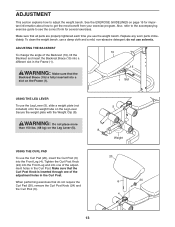
Replace any worn parts immediately. ADJUSTING THE BACKREST To change the angle of the adjustment holes in the Curl Post. WARNING: Make sure that all parts are properly tightened each time you use the Leg Lever (5), slide a weight plate (not included) onto the weight tube on the Frame (1). 19 15 1 Slot USING THE LEG LEVER To use the weight bench. Make sure that the Backrest Brace (15) is inserted through one of the adjustment holes in the Frame (1). Make sure that do not use solvents. Also, refer to the accompanying exercise guide to see the correct form for ...
Replace any worn parts immediately. ADJUSTING THE BACKREST To change the angle of the adjustment holes in the Curl Post. WARNING: Make sure that all parts are properly tightened each time you use the Leg Lever (5), slide a weight plate (not included) onto the weight tube on the Frame (1). 19 15 1 Slot USING THE LEG LEVER To use the weight bench. Make sure that the Backrest Brace (15) is inserted through one of the adjustment holes in the Frame (1). Make sure that do not use solvents. Also, refer to the accompanying exercise guide to see the correct form for ...

English Manual
Page 14
Then, insert the Small Pin (52) through the Spotter and the Upright. Make sure that both Spotters are at the same height and that both Weight Rests are fully inserted. Do not place more than 310 lbs. (136 kg), including a barbell, on the indicated side of the Uprights (11). Insert a Large Pin (13) through the Curl Arm, the Curl Arm Bushings, and the Leg Lever. WARNING: Always attach the Spotters (29) and the Weight Rests (12) on the Weight Rests. 11 12 29 13 14 The 29 13 Spotter should be attached at the same height. Adjust the other Spotter (29) and the Weight ...
Then, insert the Small Pin (52) through the Spotter and the Upright. Make sure that both Spotters are at the same height and that both Weight Rests are fully inserted. Do not place more than 310 lbs. (136 kg), including a barbell, on the indicated side of the Uprights (11). Insert a Large Pin (13) through the Curl Arm, the Curl Arm Bushings, and the Leg Lever. WARNING: Always attach the Spotters (29) and the Weight Rests (12) on the Weight Rests. 11 12 29 13 14 The 29 13 Spotter should be attached at the same height. Adjust the other Spotter (29) and the Weight ...
English Manual
Page 15
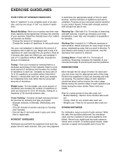
A "set smoothly and without pausing. to determine the appropriate length of time for each repetition and inhale during the exertion stage of each workout, and the numbers of repetitions and sets to complete. Muscle Building-Work your muscles near their capacity. Weight Loss-To lose weight, use a low amount of resistance and increase the number of repetitions in each set. Working Out-Include 6 to 20 repetitions as the return stage. Exhale during the return stroke. Rest for a short period of time after each set: • Muscle Building-Rest for three minutes after each set. ...
A "set smoothly and without pausing. to determine the appropriate length of time for each repetition and inhale during the exertion stage of each workout, and the numbers of repetitions and sets to complete. Muscle Building-Work your muscles near their capacity. Weight Loss-To lose weight, use a low amount of resistance and increase the number of repetitions in each set. Working Out-Include 6 to 20 repetitions as the return stage. Exhale during the return stroke. Rest for a short period of time after each set: • Muscle Building-Rest for three minutes after each set. ...
English Manual
Page 16
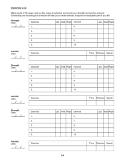
Sets Reps Exercise 6. Exercise Lbs. Sets Reps Exercise 6. 7. 8. 9. 10. EXERCISE LOG Make copies of your strength and aerobic workouts. Sets Reps 2. 7. 3. 8. 4. 9. 5. 10. Aerobic Date: Exercise Time Distance Speed Strength Date: Aerobic Date: Exercise 1. 2. 3. 4. 5. Sets Reps Exercise 6. 7. 8. 9. 10. Scheduling and recording your workouts will help you to make exercise a regular and enjoyable part of this page, and use the copies to schedule and record your life. Lbs. Sets Reps Time Distance Speed Strength Date: Aerobic Date: Exercise 1. 2. 3. 4. 5. ...
Sets Reps Exercise 6. Exercise Lbs. Sets Reps Exercise 6. 7. 8. 9. 10. EXERCISE LOG Make copies of your strength and aerobic workouts. Sets Reps 2. 7. 3. 8. 4. 9. 5. 10. Aerobic Date: Exercise Time Distance Speed Strength Date: Aerobic Date: Exercise 1. 2. 3. 4. 5. Sets Reps Exercise 6. 7. 8. 9. 10. Scheduling and recording your workouts will help you to make exercise a regular and enjoyable part of this page, and use the copies to schedule and record your life. Lbs. Sets Reps Time Distance Speed Strength Date: Aerobic Date: Exercise 1. 2. 3. 4. 5. ...
English Manual
Page 17
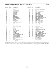
Exercise Guide * - Grease Packet Note: Specifications are not illustrated. For information about ordering replacement parts, see the back cover of this manual. *These parts are subject to change without notice. If a part is missing, please call 1-877-992-5999. 17 Userʼs Manual * - Qty. Description 1 1 Frame 2 1 Front Stabilizer 3 1 Rear Stabilizer 4 1 Front Leg 5 1 Leg Lever 6 1 Curl Post 7 1 Base 8 1 Weight Clip 9 2 Base Stabilizer 10 1 Front Leg Bushing 11 2 Upright 12 2 Weight Rest 13 4 Large Pin 14 2 95mm Round Inner Cap 15...
Exercise Guide * - Grease Packet Note: Specifications are not illustrated. For information about ordering replacement parts, see the back cover of this manual. *These parts are subject to change without notice. If a part is missing, please call 1-877-992-5999. 17 Userʼs Manual * - Qty. Description 1 1 Frame 2 1 Front Stabilizer 3 1 Rear Stabilizer 4 1 Front Leg 5 1 Leg Lever 6 1 Curl Post 7 1 Base 8 1 Weight Clip 9 2 Base Stabilizer 10 1 Front Leg Bushing 11 2 Upright 12 2 Weight Rest 13 4 Large Pin 14 2 95mm Round Inner Cap 15...
English Manual
Page 18
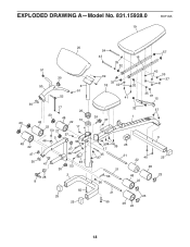
EXPLODED DRAWING A-Model No. 831.15928.0 19 R0710A 20 51 30 50 6 51 52 30 23 48 22 47 17 26 23 48 48 22 10 22 53 27 37 5 46 17 4 58 27 38 30 47 28 8 49 53 30 2 55 25 25 54 43 35 32 39 32 18 42 16 32 57 42 35 37 41 35 41 37 15 24 37 32 37 1 37 17 45 37 39 25 31 40 22 21 56 36 48 48 22 3 25 23 21 23 55 48 22 18
EXPLODED DRAWING A-Model No. 831.15928.0 19 R0710A 20 51 30 50 6 51 52 30 23 48 22 47 17 26 23 48 48 22 10 22 53 27 37 5 46 17 4 58 27 38 30 47 28 8 49 53 30 2 55 25 25 54 43 35 32 39 32 18 42 16 32 57 42 35 37 41 35 41 37 15 24 37 32 37 1 37 17 45 37 39 25 31 40 22 21 56 36 48 48 22 3 25 23 21 23 55 48 22 18
English Manual
Page 19
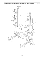
EXPLODED DRAWING B-Model No. 831.15928.0 R0710A 14 13 17 12 14 13 11 17 11 13 29 34 58 37 58 12 58 34 29 17 13 34 34 34 35 58 44 34 58 44 58 17 58 34 9 25 33 17 34 35 34 33 7 34 17 34 35 58 37 9 25 33 17 33 35 34 17 19
EXPLODED DRAWING B-Model No. 831.15928.0 R0710A 14 13 17 12 14 13 11 17 11 13 29 34 58 37 58 12 58 34 29 17 13 34 34 34 35 58 44 34 58 44 58 17 58 34 9 25 33 17 34 35 34 33 7 34 17 34 35 58 37 9 25 33 17 33 35 34 17 19

English Manual
Page 20
only) www.sears.com To purchase a protection agreement (U.S.A.) or maintenance agreement (Canada) on -line for free repair (or replacement if repair proves impossible). For the replacement parts, accessories, and user's manuals that you may also have other rights which vary from state to do-it fixed, at your home-of all major brand appliances, lawn and garden equipment, or heating and cooling systems, no matter who made it, no matter who sold it! and Canada) www.sears.com www.sears.ca Our Home For repair of carry-in material or workmanship within 90 days of the date of ...
only) www.sears.com To purchase a protection agreement (U.S.A.) or maintenance agreement (Canada) on -line for free repair (or replacement if repair proves impossible). For the replacement parts, accessories, and user's manuals that you may also have other rights which vary from state to do-it fixed, at your home-of all major brand appliances, lawn and garden equipment, or heating and cooling systems, no matter who made it, no matter who sold it! and Canada) www.sears.com www.sears.ca Our Home For repair of carry-in material or workmanship within 90 days of the date of ...
