
English Manual
Page 1
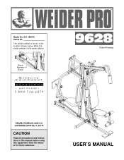
HOFFMAN ESTATES, IL 60179 CAUTION Read all precautions and instructions in this manual before using this manual for future reference. Save this equipment. Write the serial number in the location shown below. Serial Number Decal ® Patent Pending SEARS, ROEBUCK AND CO. Model No. 831.159370 Serial No. USER'S MANUAL The serial number is found in the space above.
HOFFMAN ESTATES, IL 60179 CAUTION Read all precautions and instructions in this manual before using this manual for future reference. Save this equipment. Write the serial number in the location shown below. Serial Number Decal ® Patent Pending SEARS, ROEBUCK AND CO. Model No. 831.159370 Serial No. USER'S MANUAL The serial number is found in the space above.
English Manual
Page 2
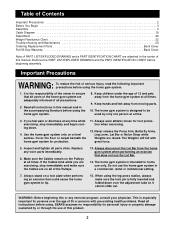
Remove the PART LIST/EXPLODED DRAWING and the PART IDENTIFICATION CHART before using the home gym system. 8. It is the responsibility of the owner to be used by or through the use the Lat Bar. 14. The home gym system is intended for protection. 11. Cover the floor or carpet beneath the home gym system for home use the home gym system in the accompanying literature before using the leg press station, always make sure the Cables are on the Pulleys at a time. 3. The home gym system is designed to ensure that does not use of this manual. Important Precautions ...
Remove the PART LIST/EXPLODED DRAWING and the PART IDENTIFICATION CHART before using the home gym system. 8. It is the responsibility of the owner to be used by or through the use the Lat Bar. 14. The home gym system is intended for protection. 11. Cover the floor or carpet beneath the home gym system for home use the home gym system in the accompanying literature before using the leg press station, always make sure the Cables are on the Pulleys at a time. 3. The home gym system is designed to ensure that does not use of this manual. Important Precautions ...
English Manual
Page 3
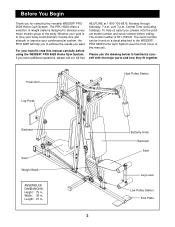
Whether your goal is 831.159370. For your cardiovascular system, the PRO 9628 will help us assist you for selecting the versatile WEIDER® PRO 9628 Home Gym System. To help you have additional questions, please call our toll-free HELPLINE at 1-800-736-6879, Monday through ...Begin Thank you , please note the product model number and serial number before using the WEIDER® PRO 9628 Home Gym System. The PRO 9628 offers a selection of the body. If you to the WEIDER® PRO 9628 Home Gym System (see the front cover of this manual carefully before calling. Butterfly Arms...
Whether your goal is 831.159370. For your cardiovascular system, the PRO 9628 will help us assist you for selecting the versatile WEIDER® PRO 9628 Home Gym System. To help you have additional questions, please call our toll-free HELPLINE at 1-800-736-6879, Monday through ...Begin Thank you , please note the product model number and serial number before using the WEIDER® PRO 9628 Home Gym System. The PRO 9628 offers a selection of the body. If you to the WEIDER® PRO 9628 Home Gym System (see the front cover of this manual carefully before calling. Butterfly Arms...
English Manual
Page 4
Assembly Note: This introduction will save you more convenient if you have included a PART IDENTIFICATION CHART located in a cleared area and remove the packing materials. Most people find that assembly stage. You may have broken it ! Place the chart on the floor or work table and use it to complete the process over a couple of time, and by setting aside plenty of evenings. All parts used in this product, be attached to complete the steps outlined here. Place all the way around the assembled equipment. The seats and all moving arms with each assembly stage to ...
Assembly Note: This introduction will save you more convenient if you have included a PART IDENTIFICATION CHART located in a cleared area and remove the packing materials. Most people find that assembly stage. You may have broken it ! Place the chart on the floor or work table and use it to complete the process over a couple of time, and by setting aside plenty of evenings. All parts used in this product, be attached to complete the steps outlined here. Place all the way around the assembled equipment. The seats and all moving arms with each assembly stage to ...
English Manual
Page 5
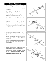
Insert four 5/16" x 2 1/2" Carriage Bolts (1) up through the Press Base (51) and secure them from falling out. Note: The mounting bracket on the Press Base (51) 1 should be sure that you have read and understood the information on the floor. 94 78 2. Do not tighten the Nylon Locknuts yet. 93 21 21 5 5 Secure the Carriage Bolts with the holes in the mounting bracket over the Carriage Bolts in 4 the two mounting brackets and the Stabilizer (5). Press a 2" Square Cover Cap (78) onto each end of the 2 Butterfly Base (4). Insert two 5/16" x 2 1/2" Carriage Bolts ...
Insert four 5/16" x 2 1/2" Carriage Bolts (1) up through the Press Base (51) and secure them from falling out. Note: The mounting bracket on the Press Base (51) 1 should be sure that you have read and understood the information on the floor. 94 78 2. Do not tighten the Nylon Locknuts yet. 93 21 21 5 5 Secure the Carriage Bolts with the holes in the mounting bracket over the Carriage Bolts in 4 the two mounting brackets and the Stabilizer (5). Press a 2" Square Cover Cap (78) onto each end of the 2 Butterfly Base (4). Insert two 5/16" x 2 1/2" Carriage Bolts ...

English Manual
Page 6
Do not tighten the Nylon Locknuts yet. 65 A Note: The Press Upright (56) must be leaning towards the center of the unit with the side arm facing outward. 56 3 3 51 1 6. Do not tighten the Nylon Locknuts yet. Hand tighten a 5/16" Nylon Locknut (3) onto each Carriage Bolt. Hand tighten a 5/16" Nylon Locknut (3) onto each Carriage Bolt. 5. Slide the Butterfly Upright (42) onto the 5/16" x 2 1/2" 6 Carriage Bolts (1) in the Press Base (51). Slide the Press Upright (56) onto the 5/16" x 2 1/2" Carriage Bolts (1) in the Butterfly Base (4). Note: The Butterfly Upright must...
Do not tighten the Nylon Locknuts yet. 65 A Note: The Press Upright (56) must be leaning towards the center of the unit with the side arm facing outward. 56 3 3 51 1 6. Do not tighten the Nylon Locknuts yet. Hand tighten a 5/16" Nylon Locknut (3) onto each Carriage Bolt. Hand tighten a 5/16" Nylon Locknut (3) onto each Carriage Bolt. 5. Slide the Butterfly Upright (42) onto the 5/16" x 2 1/2" 6 Carriage Bolts (1) in the Press Base (51). Slide the Press Upright (56) onto the 5/16" x 2 1/2" Carriage Bolts (1) in the Butterfly Base (4). Note: The Butterfly Upright must...
English Manual
Page 7
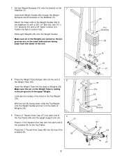
Slide eight Weights (25) onto the Weight Guides. Make sure all of the Weights are turned so the pin grooves are facing away from the center of Weights (25). 60 B 25 61 21 5 76 Pin 63 64 Pin Groove 9. With the slot (B) facing down, slide the Top Weight onto the Weight Guides and set it on the same side and are on the stack of the unit. 62 Pin Grooves 25 19 61 8. Make sure the pin on the Top Frame. Insert both Weight Guides (62) through the Weight Bumpers and the bracket on the 7 Stabilizer (5). Lubricate the insides of Weights (25). A Press two 1" Round Inner ...
Slide eight Weights (25) onto the Weight Guides. Make sure all of the Weights are turned so the pin grooves are facing away from the center of Weights (25). 60 B 25 61 21 5 76 Pin 63 64 Pin Groove 9. With the slot (B) facing down, slide the Top Weight onto the Weight Guides and set it on the same side and are on the stack of the unit. 62 Pin Grooves 25 19 61 8. Make sure the pin on the Top Frame. Insert both Weight Guides (62) through the Weight Bumpers and the bracket on the 7 Stabilizer (5). Lubricate the insides of Weights (25). A Press two 1" Round Inner ...
English Manual
Page 8
10. Hand tighten a 5/16" Nylon Locknut (3) unto each welded spacer on the Seat Frame and through the holes in steps 4 through 12. 12 27 77 3 3 11 1 51 55 42 8 3 Arm Assembly 13. Insert two 5/16" x 2 3/4" Bolts (11) through the holes in the direction shown. Align the welded spacers on the Press Frame with the tube (A) on the Uprights. 55 Insert four 5/16" x 2 3/4" Bolts (11) with the Bolt and a 3/8" Nylon Jam Nut (83). 8 13 75 83 17 59 Lubricate A 55 Note: This will be a tight fit. The Plastic Bushings should fit onto the ends of the Weight Guides (62) to the Top Frame with ...
10. Hand tighten a 5/16" Nylon Locknut (3) unto each welded spacer on the Seat Frame and through the holes in steps 4 through 12. 12 27 77 3 3 11 1 51 55 42 8 3 Arm Assembly 13. Insert two 5/16" x 2 3/4" Bolts (11) through the holes in the direction shown. Align the welded spacers on the Press Frame with the tube (A) on the Uprights. 55 Insert four 5/16" x 2 3/4" Bolts (11) with the Bolt and a 3/8" Nylon Jam Nut (83). 8 13 75 83 17 59 Lubricate A 55 Note: This will be a tight fit. The Plastic Bushings should fit onto the ends of the Weight Guides (62) to the Top Frame with ...

English Manual
Page 9
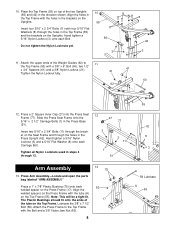
14. Note the position of each Arm. Press a 1" Round Inner Cap (49) into the lower 14 end of each Butterfly Arm (47) and (48) with two 5/16" x 2 1/2" Bolts (22) and two 5/16" Nylon Locknuts (3). 17 22 3 46 49 44 15. Attach each Press Arm to each Press Arm (46). Make sure the Long Cable Traps (50) are positioned as shown. Identify the Right Arm (48) and the Left Arm (47) by imagining yourself sitting on each Press Arm. Arm identification is very important for the next step. 15 50 6 A 7 50 6 A 47 21 48 9 Butterfly Arm Assembly Attach a "V"-Pulley (6) and a ...
14. Note the position of each Arm. Press a 1" Round Inner Cap (49) into the lower 14 end of each Butterfly Arm (47) and (48) with two 5/16" x 2 1/2" Bolts (22) and two 5/16" Nylon Locknuts (3). 17 22 3 46 49 44 15. Attach each Press Arm to each Press Arm (46). Make sure the Long Cable Traps (50) are positioned as shown. Identify the Right Arm (48) and the Left Arm (47) by imagining yourself sitting on each Press Arm. Arm identification is very important for the next step. 15 50 6 A 7 50 6 A 47 21 48 9 Butterfly Arm Assembly Attach a "V"-Pulley (6) and a ...

English Manual
Page 10
16. Lubricate both axles (A) on the Retainers (69) bend toward the Cover Cap (70), as shown, so it will hold the Cable in the same manner. 55 47 B 69 70 44 Press a 1 3/4" Square Inner Cap (44) into each Arm. 45 Axle 69 70 17. A Tap two 1" Retainers (69) and a 1" Round Cover Cap (70) onto the right axle. Attach the Bumper (82) to 17 the Press Seat Frame (77) with a 3/8" x 2 1/2" Bolt (7) and a 3/8" Nylon Locknut (21). For Cable identification and routing during steps 18-35, refer to the Cable 50 Diagram and Cable ID Chart on page 19. 55 6 Tighten the Bolt and Locknut on ...
16. Lubricate both axles (A) on the Retainers (69) bend toward the Cover Cap (70), as shown, so it will hold the Cable in the same manner. 55 47 B 69 70 44 Press a 1 3/4" Square Inner Cap (44) into each Arm. 45 Axle 69 70 17. A Tap two 1" Retainers (69) and a 1" Round Cover Cap (70) onto the right axle. Attach the Bumper (82) to 17 the Press Seat Frame (77) with a 3/8" x 2 1/2" Bolt (7) and a 3/8" Nylon Locknut (21). For Cable identification and routing during steps 18-35, refer to the Cable 50 Diagram and Cable ID Chart on page 19. 55 6 Tighten the Bolt and Locknut on ...
English Manual
Page 11
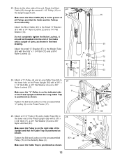
Feed the threaded end of the Short Cable (23) between the pre-assembled 3 1/2" Pulley (15) and the hook (C) on the Right Butterfly Arm (48). Make sure the Long Cable Trap (50) is positioned to hold the Cable in place. 23 22. Route the Short 21 Cable (23) around the Pulley in the direction shown. D Tighten the Bolt and Locknut on the pulley bracket (D). Route 15 the Short Cable (23) around the "V"-Pulley (6) on the Top Frame (55). Route the Short Cable (23) around the "V"-Pulley (6) on the weight support arm (A). 15 81 12 11 50 6 50 48 23 21 81 66 15 If necessary, ...
Feed the threaded end of the Short Cable (23) between the pre-assembled 3 1/2" Pulley (15) and the hook (C) on the Right Butterfly Arm (48). Make sure the Long Cable Trap (50) is positioned to hold the Cable in place. 23 22. Route the Short 21 Cable (23) around the Pulley in the direction shown. D Tighten the Bolt and Locknut on the pulley bracket (D). Route 15 the Short Cable (23) around the "V"-Pulley (6) on the Top Frame (55). Route the Short Cable (23) around the "V"-Pulley (6) on the weight support arm (A). 15 81 12 11 50 6 50 48 23 21 81 66 15 If necessary, ...
English Manual
Page 12
Route the Short 23 Cable (23) through the second 3 1/2" Pulley (15) on the Butterfly Base (4). Attach a 3 1/2" Pulley (15) and a Cable Trap (66) to the lower end of the Press Upright (56) with a 1/4" Nylon Locknut (2) and a 1/4" Flat Washer (10). Tighten the Bolt and Locknut on the pre-assembled Pulley (15) on the weight support arm. Move to the Weight Tube (63) with a 3/8" x 4 1/4" Bolt (80), a 3/8" Flat Washer (9) and a 3/8" Nylon Locknut (21). Attach the Short Cable (23) to the lower hole on the Press Upright (56) with the 5/16" x 1 3/4" Bolt (72) and a 5/16" Nylon ...
Route the Short 23 Cable (23) through the second 3 1/2" Pulley (15) on the Butterfly Base (4). Attach a 3 1/2" Pulley (15) and a Cable Trap (66) to the lower end of the Press Upright (56) with a 1/4" Nylon Locknut (2) and a 1/4" Flat Washer (10). Tighten the Bolt and Locknut on the pre-assembled Pulley (15) on the weight support arm. Move to the Weight Tube (63) with a 3/8" x 4 1/4" Bolt (80), a 3/8" Flat Washer (9) and a 3/8" Nylon Locknut (21). Attach the Short Cable (23) to the lower hole on the Press Upright (56) with the 5/16" x 1 3/4" Bolt (72) and a 5/16" Nylon ...

English Manual
Page 13
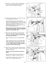
Make sure the Long Cable Trap is attached on the indi- 58 cated side of the Press Upright. 8 Route the threaded end of the bracket. Locate the Long Cable (58). It may be necessary to the Press Upright (56) with a 5/16" x 2 3/4" Bolt (11), a 5/16" Flat Washer (8) and a 5/16" Nylon Locknut (3). 6 Make sure the flat side of the closed loop is turned towards the Upright. 3 Make sure the Long Cable is positioned as shown. 6 7 27. Route the Long Cable (58) around the "V"-Pulley (6) on the Press Frame (17) in the direction shown. It has a closed loop on 27 one end ...
Make sure the Long Cable Trap is attached on the indi- 58 cated side of the Press Upright. 8 Route the threaded end of the bracket. Locate the Long Cable (58). It may be necessary to the Press Upright (56) with a 5/16" x 2 3/4" Bolt (11), a 5/16" Flat Washer (8) and a 5/16" Nylon Locknut (3). 6 Make sure the flat side of the closed loop is turned towards the Upright. 3 Make sure the Long Cable is positioned as shown. 6 7 27. Route the Long Cable (58) around the "V"-Pulley (6) on the Press Frame (17) in the direction shown. It has a closed loop on 27 one end ...

English Manual
Page 14
Move to the Long "U"-Bracket (57) with a 3/8" x 3 3/4" Bolt (71), a 3/8" Flat Washer (9) and a 3/8" Nylon Jam Nut (83). 58 57 2 10 58 57 2 10 15 4 71 15 42 83 9 86 32. Attach the Long Cable to the other . It should be threaded onto the end of the Cable only a couple of turns, as shown. 12 86 14 Attach the Pulley to the two "I"-plates (81) with the ball around the second 3 1/2" Pulley (15) on the Leg Press Arm (89) in the inset drawing. 31. Route the Long 29 Cable (58) around a 3 1/2" Pulley (15) in the direction shown. 81 Attach the 3 1/2" Pulley (15) and a Cable ...
Move to the Long "U"-Bracket (57) with a 3/8" x 3 3/4" Bolt (71), a 3/8" Flat Washer (9) and a 3/8" Nylon Jam Nut (83). 58 57 2 10 58 57 2 10 15 4 71 15 42 83 9 86 32. Attach the Long Cable to the other . It should be threaded onto the end of the Cable only a couple of turns, as shown. 12 86 14 Attach the Pulley to the two "I"-plates (81) with the ball around the second 3 1/2" Pulley (15) on the Leg Press Arm (89) in the inset drawing. 31. Route the Long 29 Cable (58) around a 3 1/2" Pulley (15) in the direction shown. 81 Attach the 3 1/2" Pulley (15) and a Cable ...
English Manual
Page 15
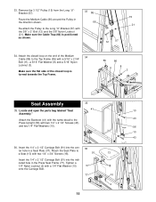
Make sure the Cable Trap (66) is turned towards the Top Frame. 55 86 8 11 3 Seat Assembly 35 35. Attach the closed loop on the end of the closed loop is positioned as shown. 33 86 66 12 57 15 21 34. Tighten a 1/4" Nylon Locknut (2) with the 3/8" x 2" Bolt (12) and the 3/8" Nylon Locknut (21). 33. Make sure the flat side of the Medium 34 Cable (86) to the Long "U"-Bracket (57) with a 1/4" Flat Washer (10) onto the Carriage Bolt. 36 91 37 77 15 13 18 10 2 Insert the 1/4" x 2 1/2" Carriage Bolt (91) into the indicated hole in a Seat Plate (37). Remove the 3...
Make sure the Cable Trap (66) is turned towards the Top Frame. 55 86 8 11 3 Seat Assembly 35 35. Attach the closed loop on the end of the closed loop is positioned as shown. 33 86 66 12 57 15 21 34. Tighten a 1/4" Nylon Locknut (2) with the 3/8" x 2" Bolt (12) and the 3/8" Nylon Locknut (21). 33. Make sure the flat side of the Medium 34 Cable (86) to the Long "U"-Bracket (57) with a 1/4" Flat Washer (10) onto the Carriage Bolt. 36 91 37 77 15 13 18 10 2 Insert the 1/4" x 2 1/2" Carriage Bolt (91) into the indicated hole in a Seat Plate (37). Remove the 3...

English Manual
Page 16
Attach the remain- 38 ing Backrest (41) to the Butterfly Seat Frame with two 1/4" x 3/4" Screws (18). Insert the 1/4" x 2" Carriage Bolt (38) into the Butterfly Seat Frame (36). Attach the other end of the unit. Press a 1 1/2" Square Inner Cap (32) into the indicated hole in a Seat Plate (37). 39 Attach the Seat Plate to the Press 37 Seat Frame (77) with a 1/4" Flat Washer (10) and a 1/4" x 2 1/2" Screw (43). 77 13 10 43 38. Tighten a 1/4" Nylon Locknut (2) with two 1/4" x 2 1/2" Screws (43) and two 1/4" Flat Washers (10). 42 41 43 10 39. Move to the other ...
Attach the remain- 38 ing Backrest (41) to the Butterfly Seat Frame with two 1/4" x 3/4" Screws (18). Insert the 1/4" x 2" Carriage Bolt (38) into the Butterfly Seat Frame (36). Attach the other end of the unit. Press a 1 1/2" Square Inner Cap (32) into the indicated hole in a Seat Plate (37). 39 Attach the Seat Plate to the Press 37 Seat Frame (77) with a 1/4" Flat Washer (10) and a 1/4" x 2 1/2" Screw (43). 77 13 10 43 38. Tighten a 1/4" Nylon Locknut (2) with two 1/4" x 2 1/2" Screws (43) and two 1/4" Flat Washers (10). 42 41 43 10 39. Move to the other ...

English Manual
Page 17
Do not overtighten the Nylon Locknut. Slide a Foam Pad (30) onto each end of the Pad Tube. 14 A 36 30 34 30 34 28 29 Miscellaneous Assembly 43 43. Make sure the Leg Press Plate and the Adjustment Tube are oriented as shown. Tighten a 5/16" Nylon Locknut (3) with a 5/16" x 2 3/4" Carriage Bolt (14) and the Seat Knob (40). 40 36 3 33 Lubricate 35 32 29 8 3 41 42 40 36 42. Slide a Foam Pad (30) onto each end of the Pad Tube. The Leg Lever must be able to the Seat Frame (36) with a 5/16" x 2 1/2" Bolt (22), two 5/16" Flat Washers (8) and a 5/16" Nylon Locknut (3). ...
Do not overtighten the Nylon Locknut. Slide a Foam Pad (30) onto each end of the Pad Tube. 14 A 36 30 34 30 34 28 29 Miscellaneous Assembly 43 43. Make sure the Leg Press Plate and the Adjustment Tube are oriented as shown. Tighten a 5/16" Nylon Locknut (3) with a 5/16" x 2 3/4" Carriage Bolt (14) and the Seat Knob (40). 40 36 3 33 Lubricate 35 32 29 8 3 41 42 40 36 42. Slide a Foam Pad (30) onto each end of the Pad Tube. The Leg Lever must be able to the Seat Frame (36) with a 5/16" x 2 1/2" Bolt (22), two 5/16" Flat Washers (8) and a 5/16" Nylon Locknut (3). ...
English Manual
Page 18
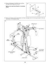
Attach the Adjustment Tube (88) to the home gym system in the locations shown in the illustration below. 45 HIGH PULLEY LEG PRESS BUTTERFLY ARM PRESS SERIAL NUMBER DECAL LOW PULLEY 18 LEG EXTENSION/CURL 44. Remove the decals from the decal sheets (not shown) and apply them to the Leg Press Arm (89) with the Small Lock Pin (90). 44 87 Make sure the Leg Press Plate (87) is oriented as shown. 88 90 89 45.
Attach the Adjustment Tube (88) to the home gym system in the locations shown in the illustration below. 45 HIGH PULLEY LEG PRESS BUTTERFLY ARM PRESS SERIAL NUMBER DECAL LOW PULLEY 18 LEG EXTENSION/CURL 44. Remove the decals from the decal sheets (not shown) and apply them to the Leg Press Arm (89) with the Small Lock Pin (90). 44 87 Make sure the Leg Press Plate (87) is oriented as shown. 88 90 89 45.
English Manual
Page 19
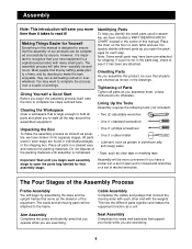
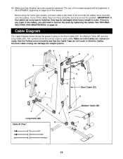
Incorrect cable routing can damage the weight system. 4 2 7 8 3 1 2 1 3 5 6 4 7 Long Cable (58) Cable ID Chart 9 8 4 5 6 2 Short Cable (23) 3 9 Medium Cable (86) 1 19 If there is used. If one of this manual. The numbers show the correct route for each cable a few times to remove the slack by tightening the cables. Make sure that the Pulleys move smoothly, find and correct the problem. See TROUBLESHOOTING AND MAINTENANCE on page 20 of the cables does not move smoothly and that the cables move smoothly over the pulleys. IMPORTANT: If the cables are routed ...
Incorrect cable routing can damage the weight system. 4 2 7 8 3 1 2 1 3 5 6 4 7 Long Cable (58) Cable ID Chart 9 8 4 5 6 2 Short Cable (23) 3 9 Medium Cable (86) 1 19 If there is used. If one of this manual. The numbers show the correct route for each cable a few times to remove the slack by tightening the cables. Make sure that the Pulleys move smoothly, find and correct the problem. See TROUBLESHOOTING AND MAINTENANCE on page 20 of the cables does not move smoothly and that the cables move smoothly over the pulleys. IMPORTANT: If the cables are routed ...
English Manual
Page 20
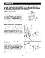
Use the WEIGHT 25 RESISTANCE CHART on the Butterfly Upright (42). First, be reduced. For some exercises, the Butterfly Seat Frame (36) must be performed. If there is any slack in the cables or chain as an exercise is performed, the effectiveness of the exercise will be sure that the attachments are in the correct starting position for each exercise. Lift the Seat Frame off the Butterfly Upright (42). 42 40 A 14 36 Attaching the Lat Bar or Nylon Strap to the High Pulley Station Attach the Lat Bar (54) to the leg lever. Adjust the length of the Chain between the ...
Use the WEIGHT 25 RESISTANCE CHART on the Butterfly Upright (42). First, be reduced. For some exercises, the Butterfly Seat Frame (36) must be performed. If there is any slack in the cables or chain as an exercise is performed, the effectiveness of the exercise will be sure that the attachments are in the correct starting position for each exercise. Lift the Seat Frame off the Butterfly Upright (42). 42 40 A 14 36 Attaching the Lat Bar or Nylon Strap to the High Pulley Station Attach the Lat Bar (54) to the leg lever. Adjust the length of the Chain between the ...